Project 1 (Mini Project on Vehicle Direction Detection
Blocks used
Inport: For input signal
Outport:Used for output
constant:used for Calibration signal
Logical Block:Used to compare Road signal with camera input
Switch Block: To compare with input and calibrated value
Mux Block: Used to combine different signal
Display Block: Used to show the Result
Logics of the system
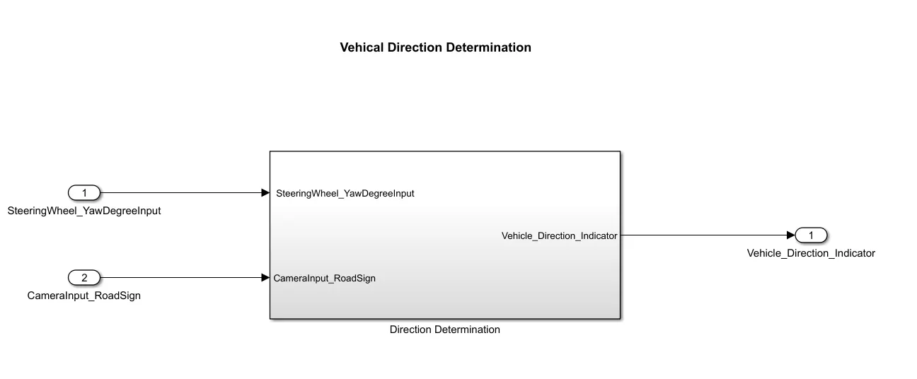
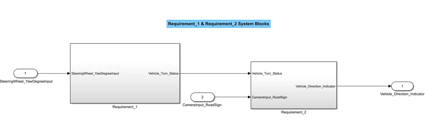
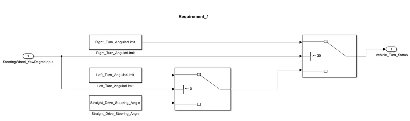
Requiremenr 1: The input of the system is the yaw rate and the yaw rate is the 30 and thresold value is also 30 if the input value will grater then 30 then switch will give true condition and vehical will take right turn, else if vehical vehical will take left turn if input value will not equal to zero becouse thresold value of second swith is 0, else input value is equal to zero then vaehical will run straight.thw output of the second block will give false condition to the frist switch and frist switch will gice the outpu of requirement 1 as Vehical turn status
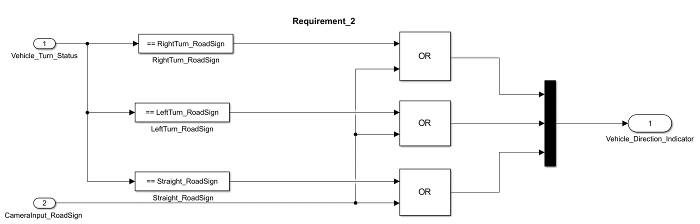
Requiremenr 2: In the second Requirement output signal of requirement 1 will compare with road signal and camera input signal for vehical direction indication.
After comparision with vahical turn status all the thre signal will campare with camera input signal as we use logical OR block and give one output and then final output will be the vehical direction indication
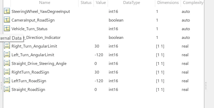
SLDD File: In the SLDD file all signal will defined like input signal output signal and calibration value
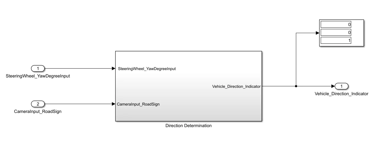
Result : we wil get the output as vehical direction identification
If we get (0 0 1) it means Vehical will run straight
If we get (1 0 0) it means Vehical will take right turn
If we get (0 1 0) it means Vehical will take left turn
Output: