Project 1 (Mini Project on Vehicle Direction Detection
STEP 1
introduction
Identifying the direction of the vehicle is one of the important & diverse features in Autonomous driving & Advanced Driver Assistance Features. This particular sub-feature of identifying the direction of the vehicle is basically identifying the direction the vehicle is taking based on the camera input.
The camera reads the road signs & stores them in its memory with unique values for a left turn, right turn & straight drive. Depending on the direction it is taking, the final indication is given to the driver – as an indication if he is driving in the recommended direction or not.
Vehicle Direction Determination can also be coupled with features like GPS systems to identify whether the vehicle is reaching its destination optimally. This sub-feature can also be used along with Lane Detection, Highway Warning, Ramp Entry / Exit in Wrong Way Detection, etc.
Step 2
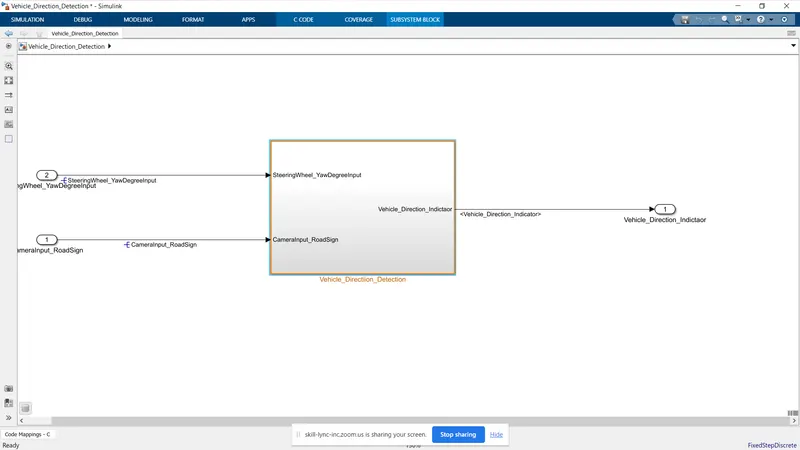
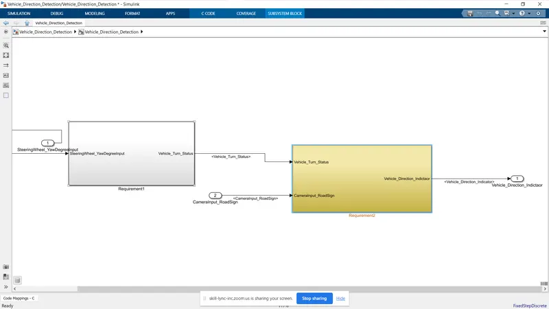
According to Requirement 1, I have developed the model
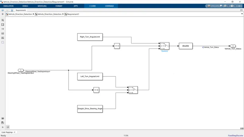
Input is SteeringWheel_YawDegreeInput compared with compared to 0 using switch according to the given condition Vehicle turn status will happen.
Requirement 1 and Requirement 2 subsystem
Requirement 1 subsystem
- As per the requirements, 1 can design this model, when the steering yaw degree is considered as input and is connected to the relational operator, and the relational operator is connected with the switch based on the if-else condition the switch is given the output as a boolean number.
- For eg if I'm given -120 deg as input means when the relation operator checks the given input once it fails means it automatically switches the false statement when the false statement is connected to the left-turn_drive so the switch has given the output the left-turn value.
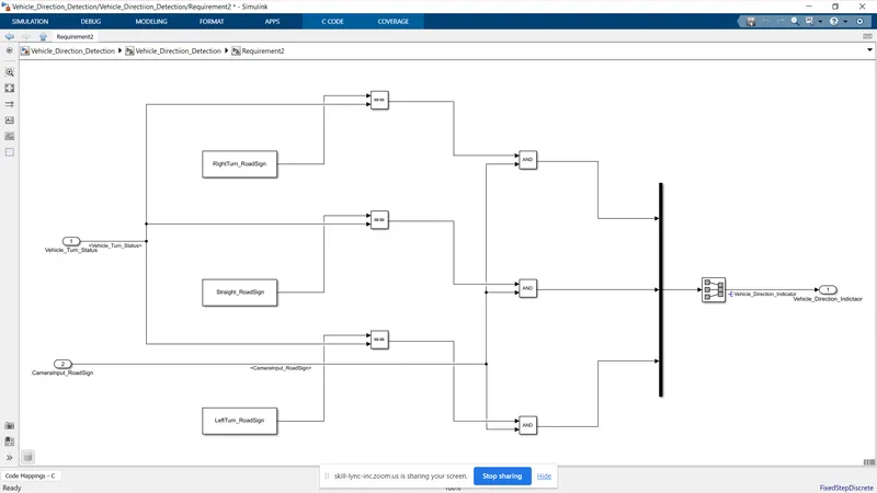
Requirement 2 Subsystem
- As per requirement statement-2 I have to compare the vehicle turn status and the camera sign once is true means the vehicle can conclude the turn is based on the road sign.
- So, I have to take the vehicle turn status as input and it would be given to the relational operator which is the road sign is compared with the vehicle turn status.
- and I use them and the gate which is used to give anyone output to the mux at a time if the left turn status is true means the right turn and straight turn will be fale so that's why I'm using the And gate in this subsystem.
- The basic objective of the subsystem is to compare the vehicle turn status with the road sign.
Step 3
Creating SLDD File
To Create a sldd file to update all the given inputs, outputs & parameters on this file later calling these variables on the Simulink blocks are shown in the fig.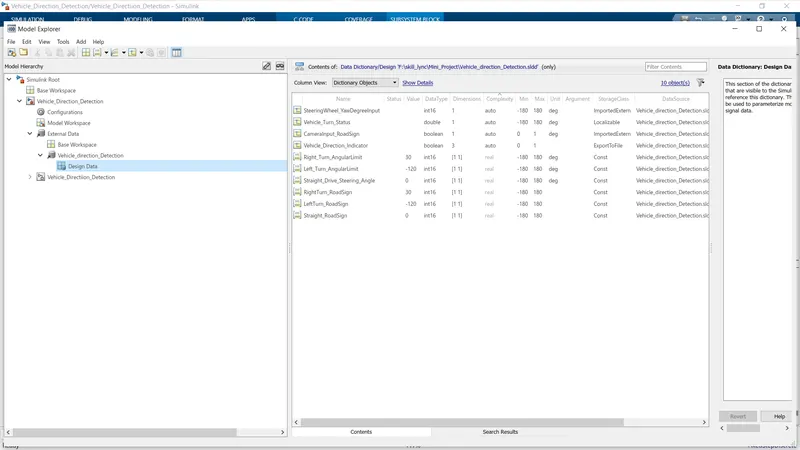
Step 4
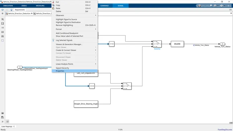
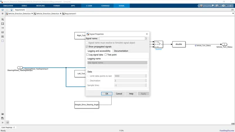
Signal Resolving and Propagation
- In this case, we have updated our signals inputs in the sldd file so we have to add the signal into the connection lines to get the proper output.
- So, we have used the resolve and propagation method on this model
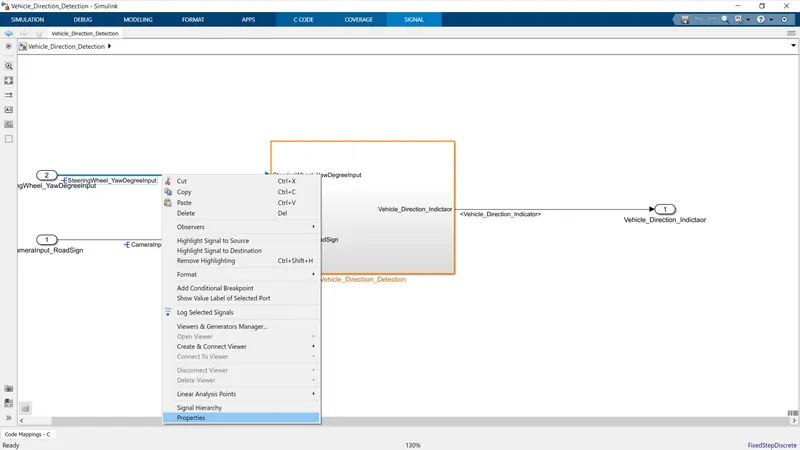
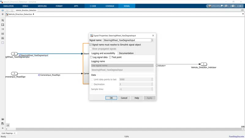
Signal Propagation
Step 5
Tagging
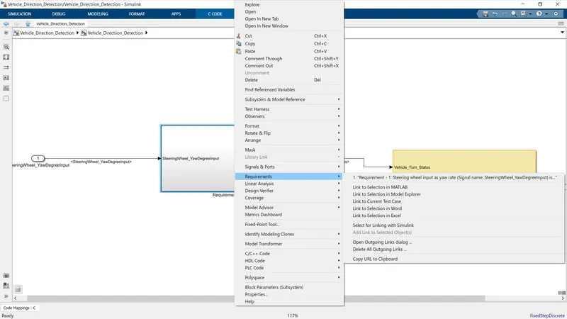
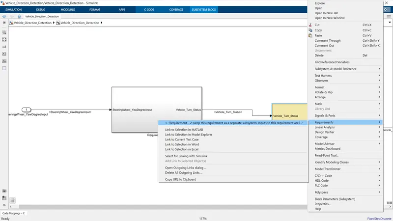
- In this project, I can update my project details and block explanation in ms word which attach with this model hereafter anyone is able to know the definition and requirements of the block means just simply click the requirement option to Simulink and automatically open the ms word file and highlight the paragraph or points.
- Make sure while doing this requirement process your ms word application should be open
- Once we right-click the subsystem then select the requirments option select the link to word or excel with our comfortable are shown above the fig.
Step 6
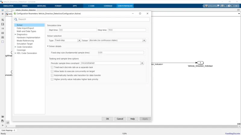
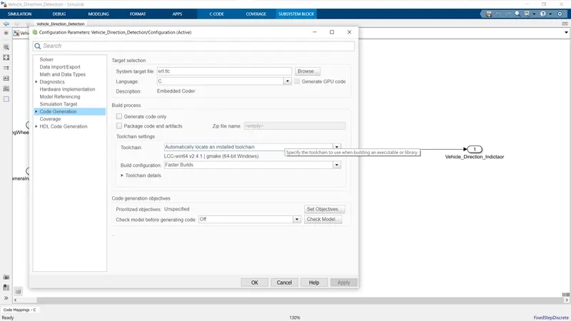
Cofiguration Parameter Update
For Code geneation tab select the file ert.tlc Embedded Coder
Step 7
Code Generation
Build Model for Generating Code
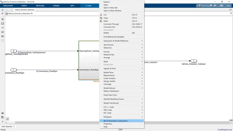
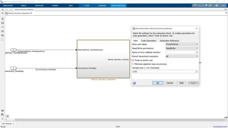
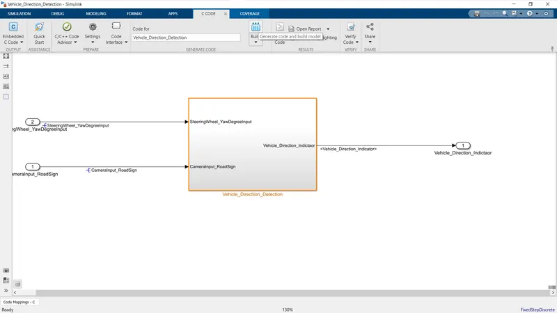
After Completiion of all Step we are able to generate the C Code successfully.
/*
* File: Vehicle_Direction_Detection.c
*
* Code generated for Simulink model 'Vehicle_Direction_Detection'.
*
* Model version : 1.5
* Simulink Coder version : 9.5 (R2021a) 14-Nov-2020
* C/C++ source code generated on : Thu Mar 2 16:41:21 2023
*
* Target selection: ert.tlc
* Embedded hardware selection: Intel->x86-64 (Windows64)
* Code generation objectives: Unspecified
* Validation result: Not run
*/
#include "Vehicle_Direction_Detection.h"
#include "Vehicle_Direction_Detection_private.h"
/* Exported data definition */
/* Definition for custom storage class: ExportToFile */
boolean_T Vehicle_Direction_Indicator[3];/* '<S3>/Signal Conversion' */
/* Const memory section */
/* Definition for custom storage class: Const */
const int16_T LeftTurn_RoadSign = -120;/* Referenced by: '<S3>/Constant2' */
const int16_T Left_Turn_AngularLimit = -120;/* Referenced by: '<S2>/Constant2' */
const int16_T RightTurn_RoadSign = 30; /* Referenced by: '<S3>/Constant' */
const int16_T Right_Turn_AngularLimit = 30;/* Referenced by: '<S2>/Constant' */
const int16_T Straight_Drive_Steering_Angle = 0;/* Referenced by: '<S2>/Constant1' */
const int16_T Straight_RoadSign = 0; /* Referenced by: '<S3>/Constant1' */
/* Real-time model */
static RT_MODEL_Vehicle_Direction_De_T Vehicle_Direction_Detection_M_;
RT_MODEL_Vehicle_Direction_De_T *const Vehicle_Direction_Detection_M =
&Vehicle_Direction_Detection_M_;
/* Model step function */
void Vehicle_Direction_Detection_step(void)
{
/* local block i/o variables */
real_T Vehicle_Turn_Status;
/* Outputs for Atomic SubSystem: '<Root>/Vehicle_Directiion_Detection' */
/* Switch: '<S2>/Switch' incorporates:
* Inport: '<Root>/SteeringWheel_YawDegreeInput'
* Switch: '<S2>/Switch1'
*/
if (SteeringWheel_YawDegreeInput >= 0) {
/* DataTypeConversion: '<S2>/Data Type Conversion' incorporates:
* Constant: '<S2>/Constant'
*/
Vehicle_Turn_Status = (real_T)Right_Turn_AngularLimit;
} else if (SteeringWheel_YawDegreeInput != 0) {
/* Switch: '<S2>/Switch1' incorporates:
* Constant: '<S2>/Constant2'
* DataTypeConversion: '<S2>/Data Type Conversion'
*/
Vehicle_Turn_Status = (real_T)Left_Turn_AngularLimit;
} else {
/* DataTypeConversion: '<S2>/Data Type Conversion' incorporates:
* Constant: '<S2>/Constant1'
* Switch: '<S2>/Switch1'
*/
Vehicle_Turn_Status = (real_T)Straight_Drive_Steering_Angle;
}
/* End of Switch: '<S2>/Switch' */
/* SignalConversion: '<S3>/Signal Conversion' incorporates:
* Constant: '<S3>/Constant'
* Constant: '<S3>/Constant1'
* Constant: '<S3>/Constant2'
* Inport: '<Root>/CameraInput_RoadSign'
* Logic: '<S3>/Logical Operator'
* Logic: '<S3>/Logical Operator1'
* Logic: '<S3>/Logical Operator2'
* RelationalOperator: '<S3>/Relational Operator'
* RelationalOperator: '<S3>/Relational Operator1'
* RelationalOperator: '<S3>/Relational Operator2'
*/
Vehicle_Direction_Indicator[0] = ((RightTurn_RoadSign == Vehicle_Turn_Status) &&
CameraInput_RoadSign);
Vehicle_Direction_Indicator[1] = ((Straight_RoadSign == Vehicle_Turn_Status) &&
CameraInput_RoadSign);
Vehicle_Direction_Indicator[2] = ((LeftTurn_RoadSign == Vehicle_Turn_Status) &&
CameraInput_RoadSign);
/* End of Outputs for SubSystem: '<Root>/Vehicle_Directiion_Detection' */
}
/* Model initialize function */
void Vehicle_Direction_Detection_initialize(void)
{
/* (no initialization code required) */
}
/* Model terminate function */
void Vehicle_Direction_Detection_terminate(void)
{
/* (no terminate code required) */
}
/*
* File trailer for generated code.
*
* [EOF]
*/