Project 1 (Mini Project on Vehicle Direction Detection
Mini Project - Vehicle Direction Determination
General Overview:
Identifying the direction of the vehicle is one of the important & diverse features in Autonomous driving & Advanced Driver Assistance Features. This particular sub-feature of identifying the direction of vehicle is basically identifying the direction the vehicle is taking based on the camera input.
Camera reads the road signs & stores into its memory with unique values for left turn, right turn & straight drive. Depending on the direction it is taking, final indication is given to the driver – as an indication if he is driving in the recommended direction or not.
Vehicle Direction Determination can also be coupled along - side features like GPS systems to identify whether the vehicle is reaching its destination in an optimized manner. This sub feature can also be used along with Lane Detection, Highway Warning, Ramp Entry / Exit in Wrong Way Detection etc.
Objective of Mini Project:
- Development of MATLAB Simulink model as per requirement.
- Tag the requirements to the simulink model; tagging requirement 1 & requirement 2 to their corresponding subsystems is fine.
- MBD compliant changes, Data Dictionary creation & code generation is added advantage, and that is not scope of this project.
- If choosing code generation, Storage class for Input signals: ImportedExtern; Storage class for Output signal: Export to File; Storage class for local signals: localizable; Storage class for calibration signals: Const.
- Choose sample time for all signals as 0.01s
Requirement - 1:
- Steering wheel input as yaw rate (Signal name: SteeringWheel_YawDegreeInput) is the input for this system.
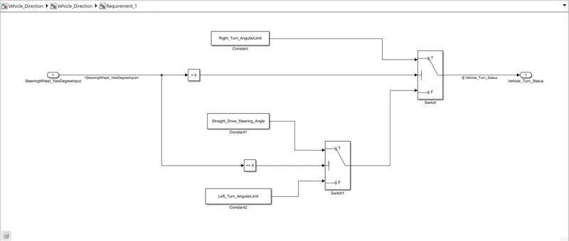
- This is compared against 3 angular values, one each for left turn, right turn & straight drive (Calibration Values: Right_Turn_AngularLimit, Left_Turn_AngularLimit, Straight_Drive_Steering_Angle) to say which specific direction the steering wheel is turning towards.
- Use switch blocks to compare & develop this requirement. Keep this requirement in a subsystem & output of this requirement is a local signal (Signal Name: Vehicle_Turn_Status).
Requirement – 2:
- Keep this requirement as a separate subsystem. Inputs to this requirement are local signal from requirement 1 (Signal Name: Vehicle_Turn_Status) & an input signal from camera (Signal Name: CameraInput_RoadSign), which confirms the occurrence of a road sign.
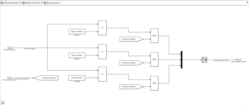
- Signal Vehicle_Turn_Status is compared against calibration values (Calibration Values: RightTurn_RoadSign, LeftTurn_RoadSign, Straight_RoadSign), if each of them is found equal, then each of the three corresponding output is compared against the camera input signal,
- Using a logical operator block, only one among them is finally given as output signal (Signal Name: Vehicle_Direction_Indicator).
Signals & Calibration Data List:
|
Signal / Calibration Name |
Signal Type |
Data Type |
Dimension |
Min |
Max |
Initial Value |
Units |
|
SteeringWheel_YawDegreeInput |
Input |
Int16 |
1 |
-180 |
180 |
- |
Deg |
|
CameraInput_RoadSign |
Input |
Boolean |
1 |
0 |
1 |
- |
- |
|
Vehicle_Turn_Status |
Local |
Int16 |
1 |
-180 |
180 |
- |
Deg |
|
Right_Turn_AngularLimit |
Calibration |
Int16 |
[1 1] |
-180 |
180 |
30 |
Deg |
|
Left_Turn_AngularLimit |
Calibration |
Int16 |
[1 1] |
-180 |
180 |
-120 |
Deg |
|
Straight_Drive_Steering_Angle |
Calibration |
Int16 |
[1 1] |
-180 |
180 |
0 |
Deg |
|
RightTurn_RoadSign |
Calibration |
Int16 |
[1 1] |
-180 |
180 |
30 |
|
|
LeftTurn_RoadSign |
Calibration |
Int16 |
[1 1] |
-180 |
180 |
-120 |
|
|
Straight_RoadSign |
Calibration |
Int16 |
[1 1] |
-180 |
180 |
0 |
|
|
Vehicle_Direction_Indicator |
Output |
Boolean |
1 |
0 |
1 |
- |
- |
Solution:
Advanced Driver Assistance Systems:
Mini Project - Vehicle Direction Determination
General Overview:
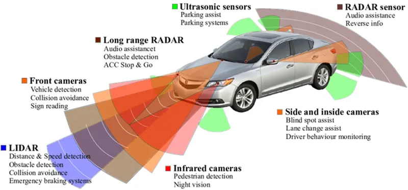
Identifying the direction of the vehicle is one of the important & diverse features in Autonomous driving & Advanced Driver Assistance Features. This particular sub-feature of identifying the direction of the vehicle is basically identifying the direction the vehicle is taking based on the camera input.
The camera reads the road signs & stores them into its memory with unique values for the left turn, right turn & straight drive. Depending on the direction it is taking, the final indication is given to the driver – as an indication if he is driving in the recommended direction or not.
Vehicle Direction Determination can also be coupled alongside features like GPS systems to identify whether the vehicle is reaching its destination in an optimized manner. This sub-feature can also be used along with Lane Detection, Highway Warning, Ramp Entry / Exit in Wrong Way Detection etc.
Objective of the Mini Project:
- Development of MATLAB Simulink model as per requirement.
- Tag the requirements to the Simulink model; tagging requirement 1 & requirement 2 to their corresponding subsystems is fine.
- MBD compliant changes, Data Dictionary creation & code generation is added advantage, and that is not the scope of this project.
- If choosing code generation, Storage class for Input signals: ImportedExtern; Storage class for Output signal: Export to File; Storage class for local signals: localizable; Storage class for calibration signals: Const.
- Choose sample time for all signals as 0.01s
Requirement - 1:
- Steering wheel input as yaw rate (Signal name: SteeringWheel_YawDegreeInput) is the input for this system.
- This is compared against 3 angular values, one each for the left turn, right turn & straight drive (Calibration Values: Right_Turn_AngularLimit, Left_Turn_AngularLimit, Straight_Drive_Steering_Angle) to say which specific direction the steering wheel is turning towards.
- Use switch blocks to compare & develop this requirement. Keep this requirement in a subsystem & the output of this requirement is a local signal (Signal Name: Vehicle_Turn_Status).
Requirement – 2:
- Keep this requirement as a separate subsystem. Inputs to this requirement are a local signal from requirement 1 (Signal Name: Vehicle_Turn_Status) & an input signal from the camera (Signal Name: CameraInput_RoadSign), which confirms the occurrence of a road sign.
- Signal Vehicle_Turn_Status is compared against calibration values (Calibration Values: RightTurn_RoadSign, LeftTurn_RoadSign, Straight_RoadSign), if each of them is found equal, then each of the three corresponding output is compared against the camera input signal,
- Using a logical operator block, only one among them is finally given as output signal (Signal Name: Vehicle_Direction_Indicator).
Signals & Calibration Data List:
|
Signal / Calibration Name |
Signal Type |
Data Type |
Dimension |
Min |
Max |
Initial Value |
Units |
|
SteeringWheel_YawDegreeInput |
Input |
Int16 |
1 |
-180 |
180 |
- |
Deg |
|
CameraInput_RoadSign |
Input |
Boolean |
1 |
0 |
1 |
- |
- |
|
Vehicle_Turn_Status |
Local |
Int16 |
1 |
-180 |
180 |
- |
Deg |
|
Right_Turn_AngularLimit |
Calibration |
Int16 |
[1 1] |
-180 |
180 |
30 |
Deg |
|
Left_Turn_AngularLimit |
Calibration |
Int16 |
[1 1] |
-180 |
180 |
-120 |
Deg |
|
Straight_Drive_Steering_Angle |
Calibration |
Int16 |
[1 1] |
-180 |
180 |
0 |
Deg |
|
RightTurn_RoadSign |
Calibration |
Int16 |
[1 1] |
-180 |
180 |
30 |
|
|
LeftTurn_RoadSign |
Calibration |
Int16 |
[1 1] |
-180 |
180 |
-120 |
|
|
Straight_RoadSign |
Calibration |
Int16 |
[1 1] |
-180 |
180 |
0 |
|
|
Vehicle_Direction_Indicator |
Output |
Boolean |
1 |
0 |
1 |
- |
- |
Steps Followed:
1. Setting up the Project File path:
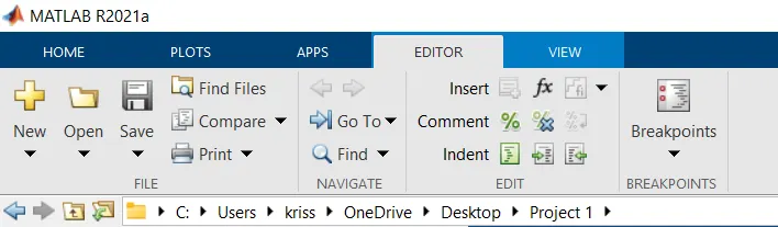
We must create the folder for project where MATLAB is installed so that we can perform the steps without any errors.
The path for the project is shown below:
2. Creating SLDD (Simulink Data Directory) File:
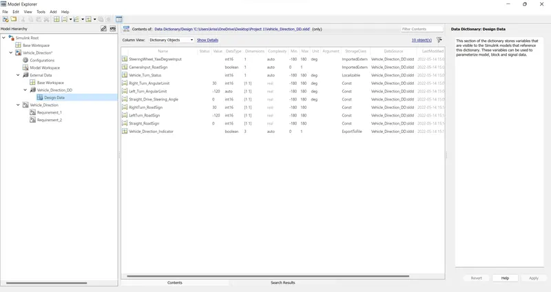
As the given list we must create the SLDD File so that all the Signals and Calibration Data mentioned is defined in order to run the model as per the list.
The benefits of creating SLDD File are:
- Data created in SLDD is persistent.
- We are able to store configuration parameters.
- It allows for traceability from data object to Simulink Selection.
Here, we have created the SLDD File as mentioned below:
3. Creating Simulink Model as per Requirements:
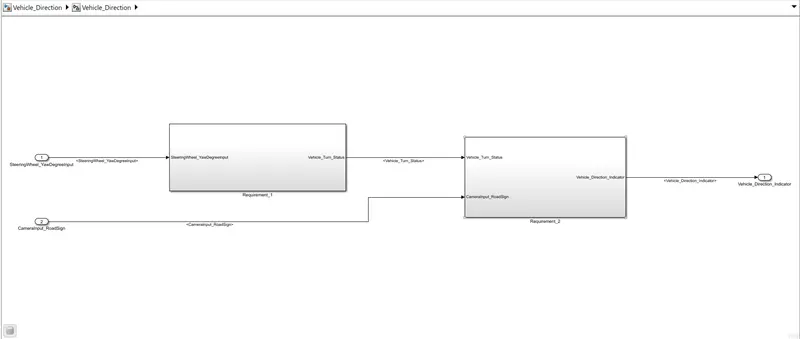
For the given requirements we have created model by naming "Vehicle_Direction" as mentioned below:
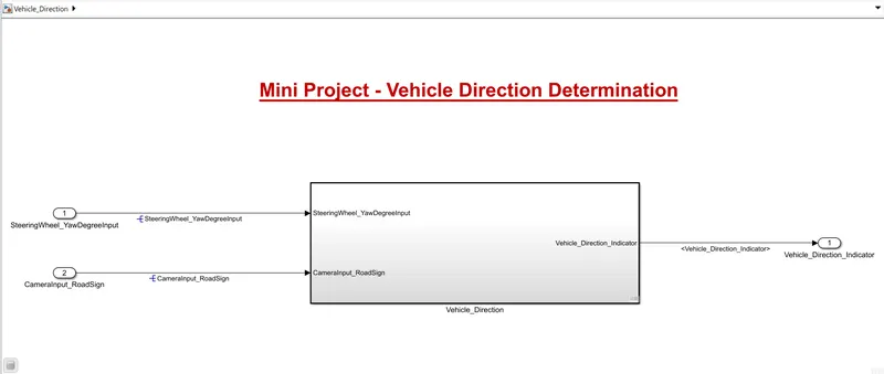
Now, here we have used to subsystem as per the requirements mentioned the images of following can be shown below:
4. Signal Resolving and Signal Propagation:
After creating Simulink Model as per requirements the next step comes is to Signal Resolving.
In this we select the Signal which needs to Resolved and then setup for Resolving. The settings for the same are mentioned below:
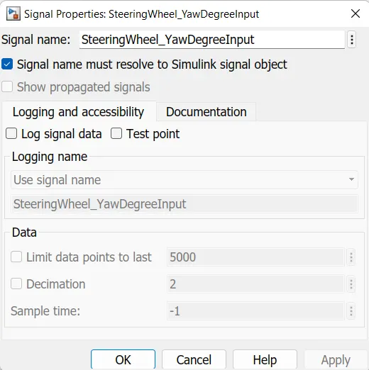
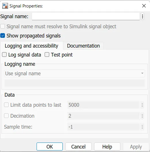
Once, the Signal is Resolved we need to follow Signal Propagation if the same signal is again taken in the model.
The settings for the same is mentioned below:
5. Setting up to Solver Configuration:
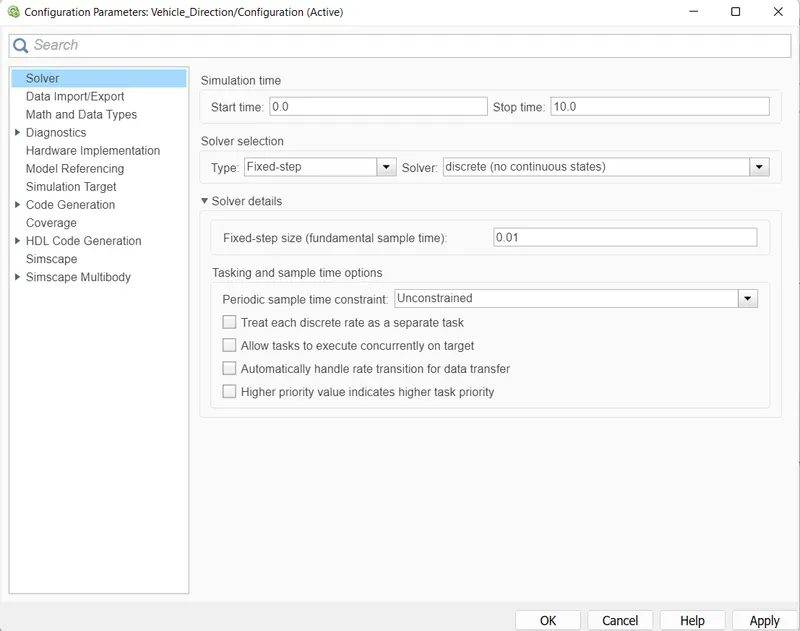
After the Signal Resolving and Signal Propagation for each signals, we need to set up the Solver for proper running of Model for Testing.
The settings for configuring Solver is mentioned as below:
6. Requirements Tagging:
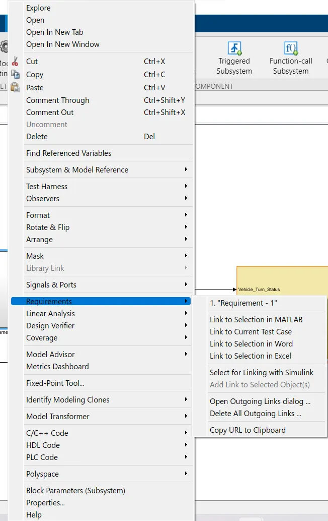
We need this step so that we can showcase the requirements as per the model is build to the third-party person who will be handling that particular model.
The requirements are tagged to the file in which it is created it can be Word or Excel format file.
The setting for Tagging is shown below:
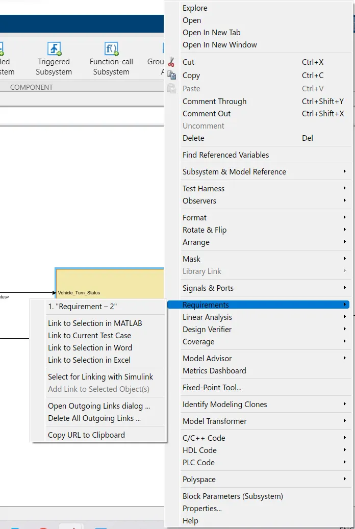
The requirements are as follows:
- Requirement - 1:
- Steering wheel input as yaw rate (Signal name: SteeringWheel_YawDegreeInput) is the input for this system.
- This is compared against 3 angular values, one each for the left turn, right turn & straight drive (Calibration Values: Right_Turn_AngularLimit, Left_Turn_AngularLimit, Straight_Drive_Steering_Angle) to say which specific direction the steering wheel is turning towards.
- Use switch blocks to compare & develop this requirement. Keep this requirement in a subsystem & the output of this requirement is a local signal (Signal Name: Vehicle_Turn_Status).
- Requirement – 2:
- Keep this requirement as a separate subsystem. Inputs to this requirement are a local signal from requirement 1 (Signal Name: Vehicle_Turn_Status) & an input signal from the camera (Signal Name: CameraInput_RoadSign), which confirms the occurrence of a road sign.
- Signal Vehicle_Turn_Status is compared against calibration values (Calibration Values: RightTurn_RoadSign, LeftTurn_RoadSign, Straight_RoadSign), if each of them is found equal, then each of the three corresponding output is compared against the camera input signal,
- Using a logical operator block, only one among them is finally given as output signal (Signal Name: Vehicle_Direction_Indicator).
7. MAB (MathWorks Advisory Board) Testing:
After setting up model we move towards MAB (MathWorks Advisory Board) Testing which is defined as:
The MAB Guidelines are a set of modeling guidelines developed by an independent industry working group for the usage of MATLAB®, Simulink®, Stateflow® and Embedded Coder®. The guidelines are the culmination of years of engineering expertise and best practices for developing, maintaining and documenting control algorithm models used in the development of production software.
The MAB guidelines are an important basis for project success and teamwork - both in-house and when cooperating with partners or subcontractors. Observing the guidelines is one key prerequisite to achieve:
- System integration without problems.
- Well-defined interfaces.
- Uniform appearance of models, code and documentation.
- Reusable models.
- Readable models.
- Problem-free exchange of models.
- A simple, effective process.
- Professional documentation.
- Understandable presentations.
- Fast software changes.
- Cooperation with subcontractors.
- Handing over of research or predevelopment projects to product development.
The steps for MAB Testing is shown below:
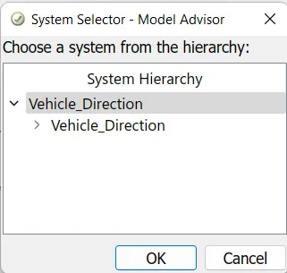
Choose the model to be MAB Tested.
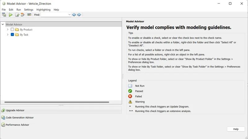
Expand the "By Task" section.
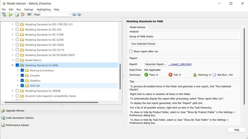
Select the "Modelling Standards for MAB" and after that click on "Run Selected Checks" for performing MAB Testing.
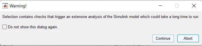
The warning dialogue box pops-up we need to click on "Continue" button.

After clicking on confirmation, the test is being processed as shown above.
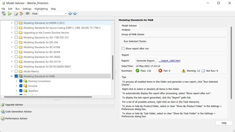
After MAB Test is performed we are seeing the results, here we need "Errors: 0" and "Warnings: Upto 15" if its more than that perform the MAB testing after resolving the errors and warnings.
In our model since it has "Errors: 0" and "Warnings: 12" so MAB Testing is Successful.
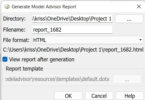
By clicking on "Generate Report" it will popup this window as mentioned above.
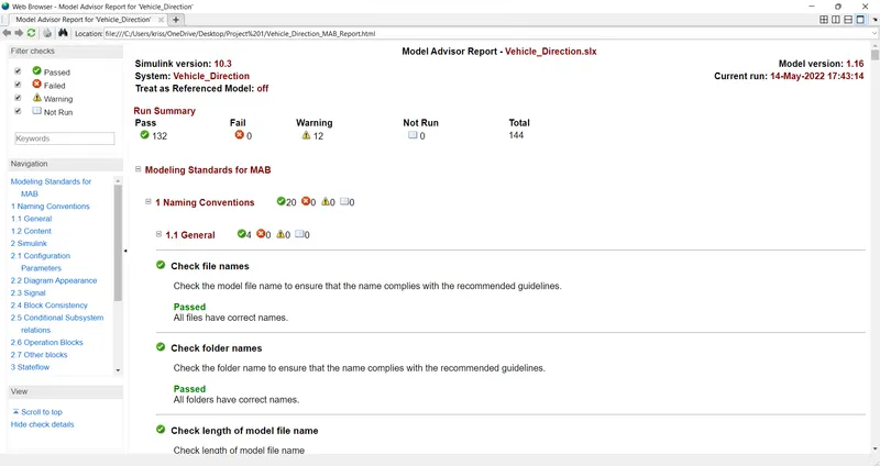
As shown above, the MAB Report is generated for the Model which is tested.
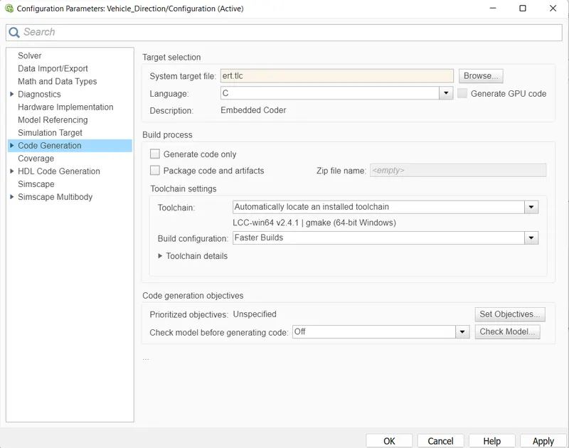
8. Generation of Embedded Code:
Once we do MAB Testing and we get '0' Errors for the created model then we further move for Code Geberation.
In this the Model which we created in Simulink environment is represented in the form of "Embedded C" Coding. So that we can fed this model logic into the Hardware which is designed for that particular application.
The steps for Code Generation is shown below:

Click on "Build" to start the code generation.
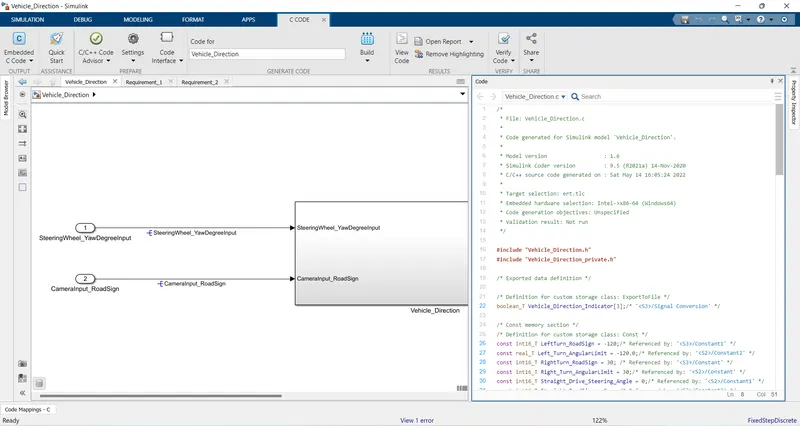
The generated code for the model is mentioned below.
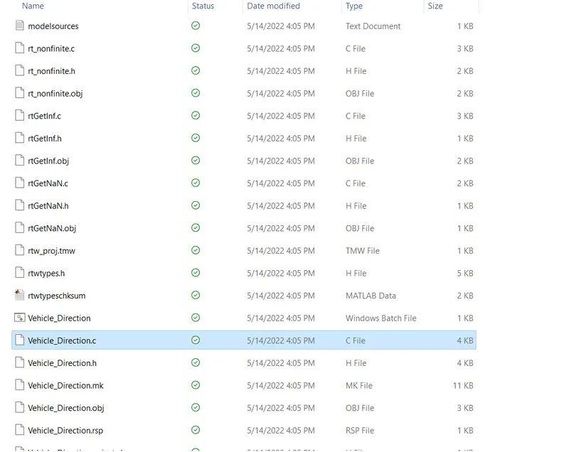
The location for the code is shown below named as "Vehicle_Direction.c".
Generated code format:
/*
* File: Vehicle_Direction.c
*
* Code generated for Simulink model 'Vehicle_Direction'.
*
* Model version : 1.6
* Simulink Coder version : 9.5 (R2021a) 14-Nov-2020
* C/C++ source code generated on : Sat May 14 16:05:24 2022
*
* Target selection: ert.tlc
* Embedded hardware selection: Intel->x86-64 (Windows64)
* Code generation objectives: Unspecified
* Validation result: Not run
*/
#include "Vehicle_Direction.h"
#include "Vehicle_Direction_private.h"
/* Exported data definition */
/* Definition for custom storage class: ExportToFile */
boolean_T Vehicle_Direction_Indicator[3];/* '<S3>/Signal Conversion' */
/* Const memory section */
/* Definition for custom storage class: Const */
const int16_T LeftTurn_RoadSign = -120;/* Referenced by: '<S3>/Constant1' */
const real_T Left_Turn_AngularLimit = -120.0;/* Referenced by: '<S2>/Constant2' */
const int16_T RightTurn_RoadSign = 30; /* Referenced by: '<S3>/Constant' */
const int16_T Right_Turn_AngularLimit = 30;/* Referenced by: '<S2>/Constant' */
const int16_T Straight_Drive_Steering_Angle = 0;/* Referenced by: '<S2>/Constant1' */
const int16_T Straight_RoadSign = 0; /* Referenced by: '<S3>/Constant2' */
/* Real-time model */
static RT_MODEL_Vehicle_Direction_T Vehicle_Direction_M_;
RT_MODEL_Vehicle_Direction_T *const Vehicle_Direction_M = &Vehicle_Direction_M_;
/* Model step function */
void Vehicle_Direction_step(void)
{
/* local block i/o variables */
int16_T Vehicle_Turn_Status;
real_T tmp;
/* Switch: '<S2>/Switch' incorporates:
* Constant: '<S4>/Constant'
* Constant: '<S5>/Constant'
* Inport: '<Root>/SteeringWheel_YawDegreeInput'
* RelationalOperator: '<S4>/Compare'
* RelationalOperator: '<S5>/Compare'
* Switch: '<S2>/Switch1'
*/
if (SteeringWheel_YawDegreeInput > 0) {
/* Switch: '<S2>/Switch' incorporates:
* Constant: '<S2>/Constant'
*/
Vehicle_Turn_Status = Right_Turn_AngularLimit;
} else if (SteeringWheel_YawDegreeInput == 0) {
/* Switch: '<S2>/Switch1' incorporates:
* Constant: '<S2>/Constant1'
* Switch: '<S2>/Switch'
*/
Vehicle_Turn_Status = Straight_Drive_Steering_Angle;
} else {
/* Switch: '<S2>/Switch1' incorporates:
* Constant: '<S2>/Constant2'
*/
tmp = floor(Left_Turn_AngularLimit);
if (rtIsNaN(tmp) || rtIsInf(tmp)) {
tmp = 0.0;
} else {
tmp = fmod(tmp, 65536.0);
}
/* Switch: '<S2>/Switch' incorporates:
* Switch: '<S2>/Switch1'
*/
Vehicle_Turn_Status = (int16_T)(tmp < 0.0 ? (int32_T)(int16_T)-(int16_T)
(uint16_T)-tmp : (int32_T)(int16_T)(uint16_T)tmp);
}
/* End of Switch: '<S2>/Switch' */
/* SignalConversion: '<S3>/Signal Conversion' incorporates:
* Constant: '<S3>/Constant'
* Constant: '<S3>/Constant1'
* Constant: '<S3>/Constant2'
* Inport: '<Root>/CameraInput_RoadSign'
* Logic: '<S3>/AND'
* Logic: '<S3>/AND1'
* Logic: '<S3>/AND2'
* RelationalOperator: '<S3>/Equal'
* RelationalOperator: '<S3>/Equal1'
* RelationalOperator: '<S3>/Equal2'
*/
Vehicle_Direction_Indicator[0] = ((Vehicle_Turn_Status == RightTurn_RoadSign) &&
CameraInput_RoadSign);
Vehicle_Direction_Indicator[1] = ((Vehicle_Turn_Status == LeftTurn_RoadSign) &&
CameraInput_RoadSign);
Vehicle_Direction_Indicator[2] = ((Vehicle_Turn_Status == Straight_RoadSign) &&
CameraInput_RoadSign);
}
/* Model initialize function */
void Vehicle_Direction_initialize(void)
{
/* Registration code */
/* initialize non-finites */
rt_InitInfAndNaN(sizeof(real_T));
}
/* Model terminate function */
void Vehicle_Direction_terminate(void)
{
/* (no terminate code required) */
}
/*
* File trailer for generated code.
*
* [EOF]
*/
9. Performing Machine-in-Loop (MIL) Testing:
For performing Machine-in-Loop (MIL) Testing we need to first create "Test Harness" for the model to be tested. The steps including for the testing are shown below:
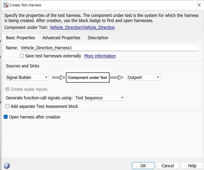
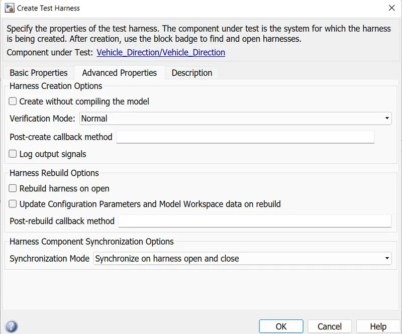
Once the Test Harness is created we need to build the signal for running the model, it is done by giving input from Signal Builder block. The input signal is shown below:
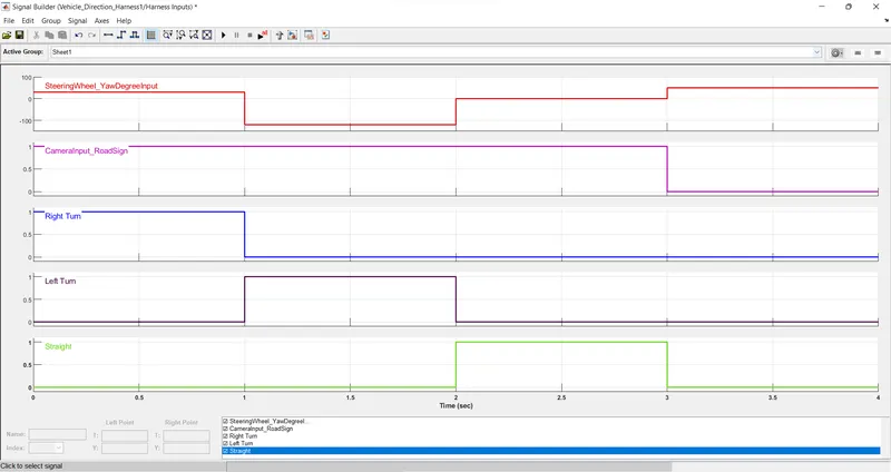
After setting up input signal we then connect up the signals via sum block and display the plots with Scope block. The final model is shown below:
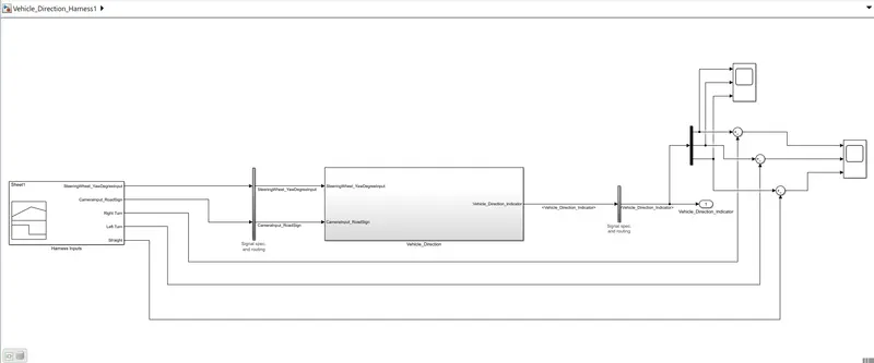
- Results:
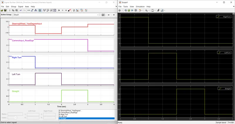
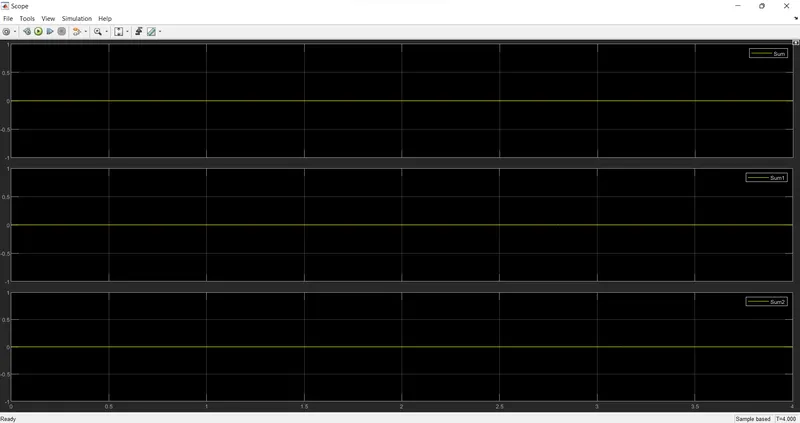
By comparing the Input signal and Output signal we can observe that both signals cancel out each other, thus '0' output is visible it means that our Model Tested is working properly as desired.
The plots for the same is shown below:
10. Performing Software-in-Loop (MIL) Testing:
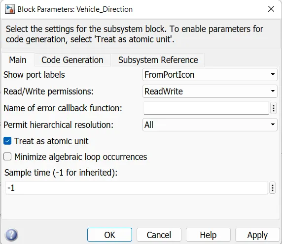
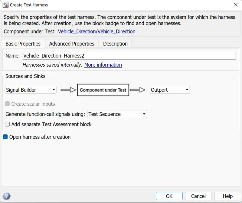
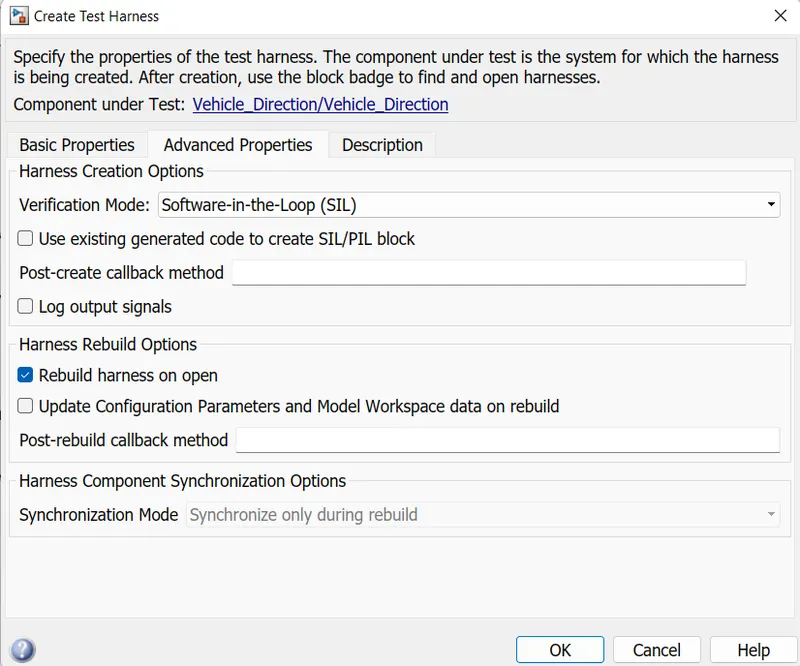
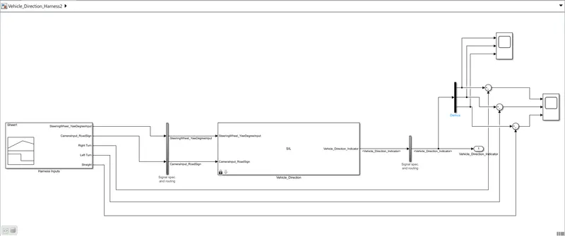
For performing Software-in-Loop (MIL) Testing we need to first create "Test Harness" for the model to be tested. We need to set the Model to "Atomic Unit" for SIL Testing.
The steps including for the testing are shown below:
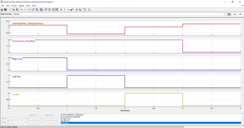
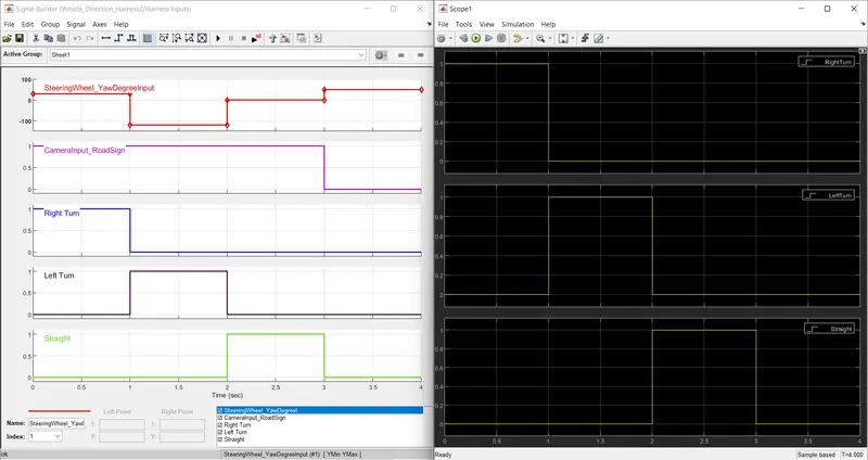
Once the Test Harness is created we need to build the signal for running the model, it is done by giving input from Signal Builder block. The input signal is shown below:
After setting up input signal we then connect up the signals via sum block and display the plots with Scope block. The final model is shown below:
- Results:
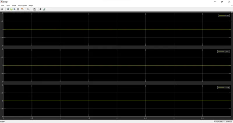
By comparing the Input signal and Output signal we can observe that both signals cancel out each other, thus '0' output is visible it means that our Model Tested is working properly as desired.
The plots for the same is shown below:
- Conclusion:
- By following the Requirements we have created the Model as well as validated as per MAB Guidelines in which we have no errors in our created Model.
- Afterwards we successfully generated Embedded C code for the Model created.
- We also have performed MIL Testing where the resultant output is as per the input given which shows that the model is properly functioning.
- Also for SIL Testing the resultant output is equal to the given input which means the model passes both the Testing Methods.