Project 1-Meshing of Rear Wheel Holder challenge
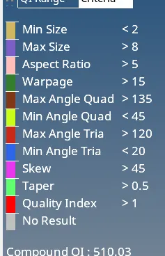
Target Element Length = 5 Units
| S.N | Quality Criteria | Value |
| 1 | Aspect Ratio | 5 |
| 2 | Skewness | 45 |
| 3 | Warping | 15 |
| 4 | Taper | 0.5 |
| 5 | Min. Length | 2 Units |
| 6 | Max. Length | 8 Units |
| 7 | Min angle Quad | 45 |
| 8 | Max angle Quad | 135 |
| 9 | Min angle Tria | 20 |
| 10 | Max angle Tria | 120 |
| 10 | Tria % | 10 |
Procedure:-
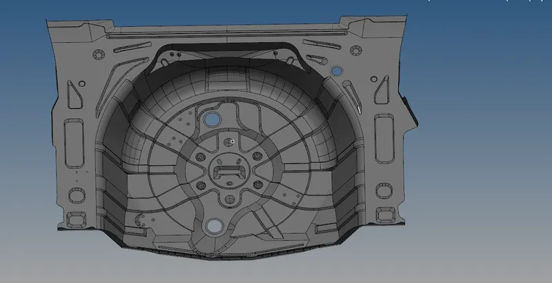
1. Import the model.
* First import the given model into the hypermesh environment using the import command.
2. Geometry cleanup and topology:
* After importing the model we have to check the geometry for errors. we can clear the errors with cleaning tools such as quick edit tool , surface edit tools, etc.
* In this process we also check for free edges , gaps , overlaped surface and T-edges.
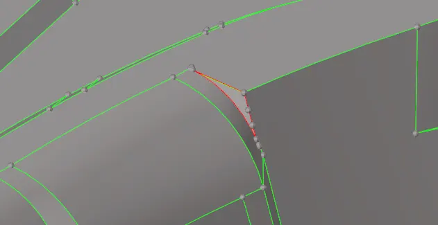
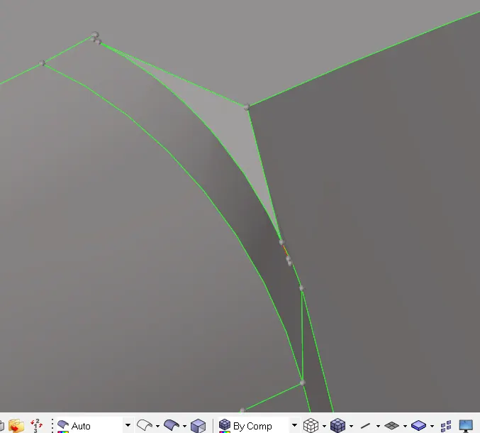
The surface here is having a geometric error where the surface has a free edge and distorted edges. By deleting the surface and creating a new surface using ruled surface from the surface deck. Select surface deck and select the free lines.
3. Mid surface extraction:
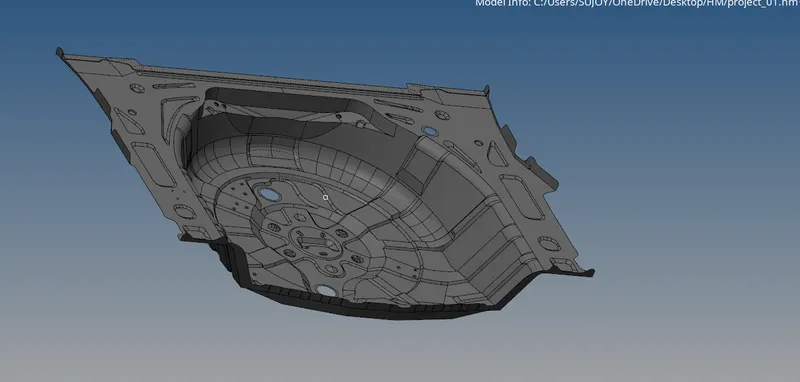
1. For extraction of mid-surface first we have to check thickness of surfaces so that we can decide whether go for manual or auto mid surface extraction.
2.We use the extraction of automidsurface.( 0ffset +planes+sweeps).
3. Given auto midsuface is created in free edges and not a proper feature.
4.Then we use quick edit panel in such as toggle and point to point replace all the overlapping or geometric interference line as well.
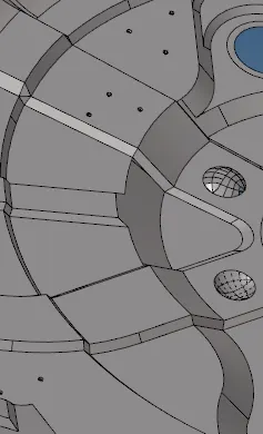
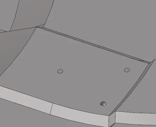
The pin hole here will cause the mesh to disturb thus the pinholes are deleted and the surface is filled by ruled surface. it can also be filled with spline/filler command.
Pinholes in the geometry before cleanup.
Surface after removal of pinholes.
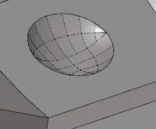
Toggled edge for the indention which will cause errors in the mesh.
Meshing
1. Start meshing form the least free edges,Like start meshing from the center.
2.It will be easy to get proper mesh flow and we will get uniform mesh density.
3 .Meshing form the edges will lead to errors and will be difficult to fix thus recommended to start meshing from the centre.
4Choose the element type while meshing.
5.For this component we will be using mixed element type and working on it.
6.We can also quads element type.This type can be used when we have rectangular surface.
7.We can use Tria Element type.This type can be used for 3d tetra meshing.
8.Now if we mesh on the curved surfaces,Choose the mesh type as mixed and mesh.
9.If we choose quad mesh type,The mesh will fail,It won't occur on the surfaces.
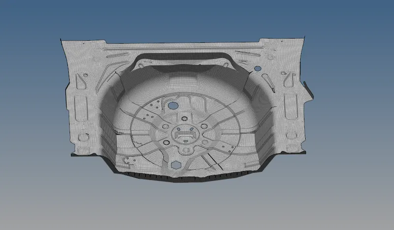
Criteria for meshing is defined and the model is remeshed and rebuilt as per the specific criteria.
Remesh-
- Remesh is used to generate a mesh of plate elements using surface geometry or existing shell elements to define the mesh area.
- The inferred surface algorithm interpolates geometry datafrom the selected elements in order to create new mesh.
- When elements are selected to be re-meshed, there is the break connectivity option and the vertex angle parameter. The break connectivity option detaches the node connectivity between adjacent selected and unselected elements. This allows you to adjust the node densities along the boundary of the selected elements.
- The vertex angle parameter defines the placement of vertices along the boundary of the selected elements. If the angle between two adjacent element edges along the boundary is less the specified angle, a vertex is placed at the meeting point of the two edges.
- Anchor nodes create the effect of a fixed point on the inferred surface (which is derived from the existing mesh) and keep the location of the anchor nodes intact.
Rebuild Mesh-
1. It is the process of remeshing existing meshes to generate a new mesh with good quality and flow.
2.The rebuild mesh functionality utilizes the same parameter and criteria files used by BatchMesher to define the quality criteria and relevant mesh parameters.
3.Rebuild is currently supported for first-order 2D meshes that are not attached to 3D element faces.
4.The rebuild algorithm is useful for many different applications like
Result -
1.Hence the mid surface has been extracted from the parent geometry.
2.Hence there are no surface deformations in the geometry.
3.A well connectivity has been established between the surfaces.
4.The features have been captured properly.
5.A good mesh flow have been achieved with the zero elements failing for quality
6.Hence tria percentage with 2.3 % have been achieved.