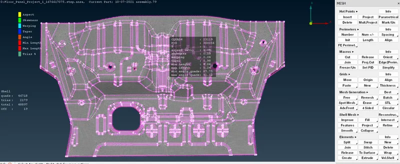
Project 1 - Meshing of Floor Panel
AIM:-
To mesh the given floor panel for the given quality criterias without any failure in the elements.
Step 1-
The cad model is imported into the Ansa software by clicking File ---> New command.
Step 2-
Then the important step is to check the geometry of the CAD model. This will helps us to clear all the surface errors, unwanted cons, and any disruptions placed in the CAD model.
This can be done by giving the command Tools ---> Checks ---> Geometry. And when you check for the geometry, some of the errors will be thrown out by ANSA.To fix the error first go for Autofix option if not clear by auto fix then clear manually
Step 3- Then we will go for the mid surface creation.Before extracting the Mid surface of the components, its important to measure their thickness. And this can be achieved by using the command "Measure". And by chosing the extreme end of two hotpoints we can get the thickness of the geometry.
then extract the mid surface by using offset option
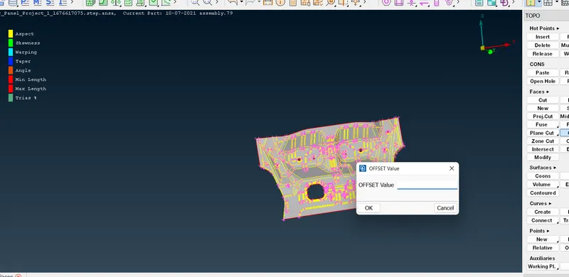
after creating the midsurface again check for geometry check up
Step 4-Once the Mid surface is generated, the CAD model is now ready for the meshnig.
Then choose Utilities ---> Mesh parameters and give the target length as 5 and give the following setup to the meah parameters dialog box.
| S.N | Quality Criteria | Value |
| 1 | Aspect Ratio | 5 |
| 2 | Skewness | 45 |
| 3 | Warping | 15 |
| 4 | Taper | 0.5 |
| 5 | Min. Length | 2 Units |
| 6 | Max. Length | 8 Units |
| 7 | Min angle Quad | 45 |
| 8 | Max angle Quad | 135 |
| 9 | Min angle Tria | 20 |
| 10 | Max angle Tria | 120 |
| 10 | Tria % | 10 |
these are the quality parameters we need to apply on the product and will check that any meshing pattern should not fail these qualities criterias
Step5- For meshing choose Mesh Generation ---> Best Mesh command and choose the faces to be meshed one by one like a flow.
In the mesh, the following things should be observed :-
1) The mesh should be smooth and clean
2) Back to Back trias should be avoided
3) Tow opposite trias nearer to eachother should be avoided
4) Tria elements in the fillets should be avoided
5) Tria elements in adjacent to outer edges should be removed
6) Tria elements attached to the hole edges should be avoided
Step 6- for better meshflow these below commands are used
Shell mesh ---> Reconstruct and Shell mesh ---> Smooth commands are also used to obtain the smooth elements in our meshed model.
Elements ---> Split , Elements ---> Swap, Grids ---> Paste, Collapse These commands are used to move the trias forward and backword and also to split them . Elements ---> Join command is also used to reshape many tria elements and by using these comannds we can achieve the conditions and the tria elements can be avoided.