Project 1 - Meshing of Floor Panel
Meshing of Floor Panel Using Ansa v24.1.2
Input Model
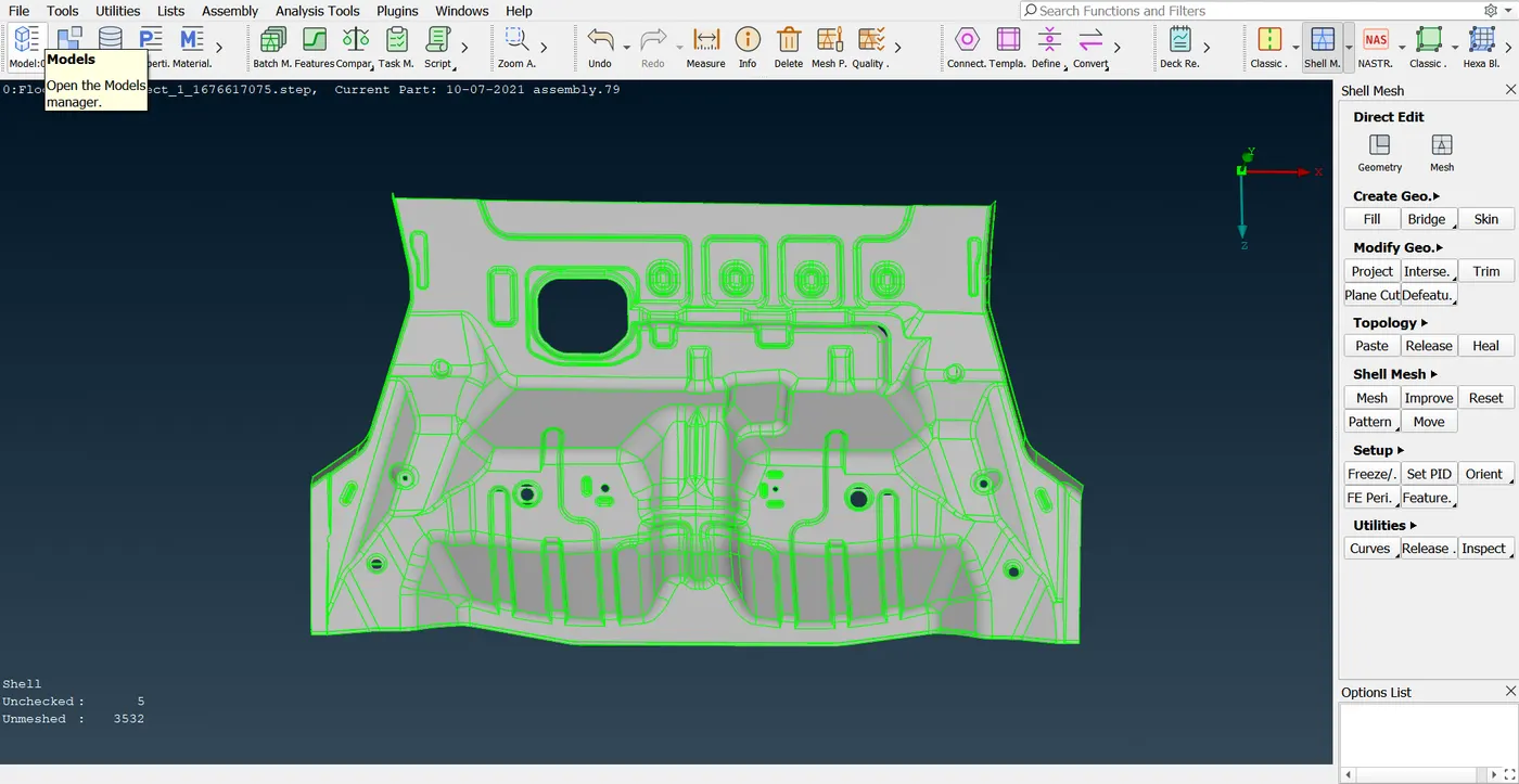
Aim: Mesh the given floor panel model with industrial standards, ensuring proper mesh flow while meeting the specified quality criteria.
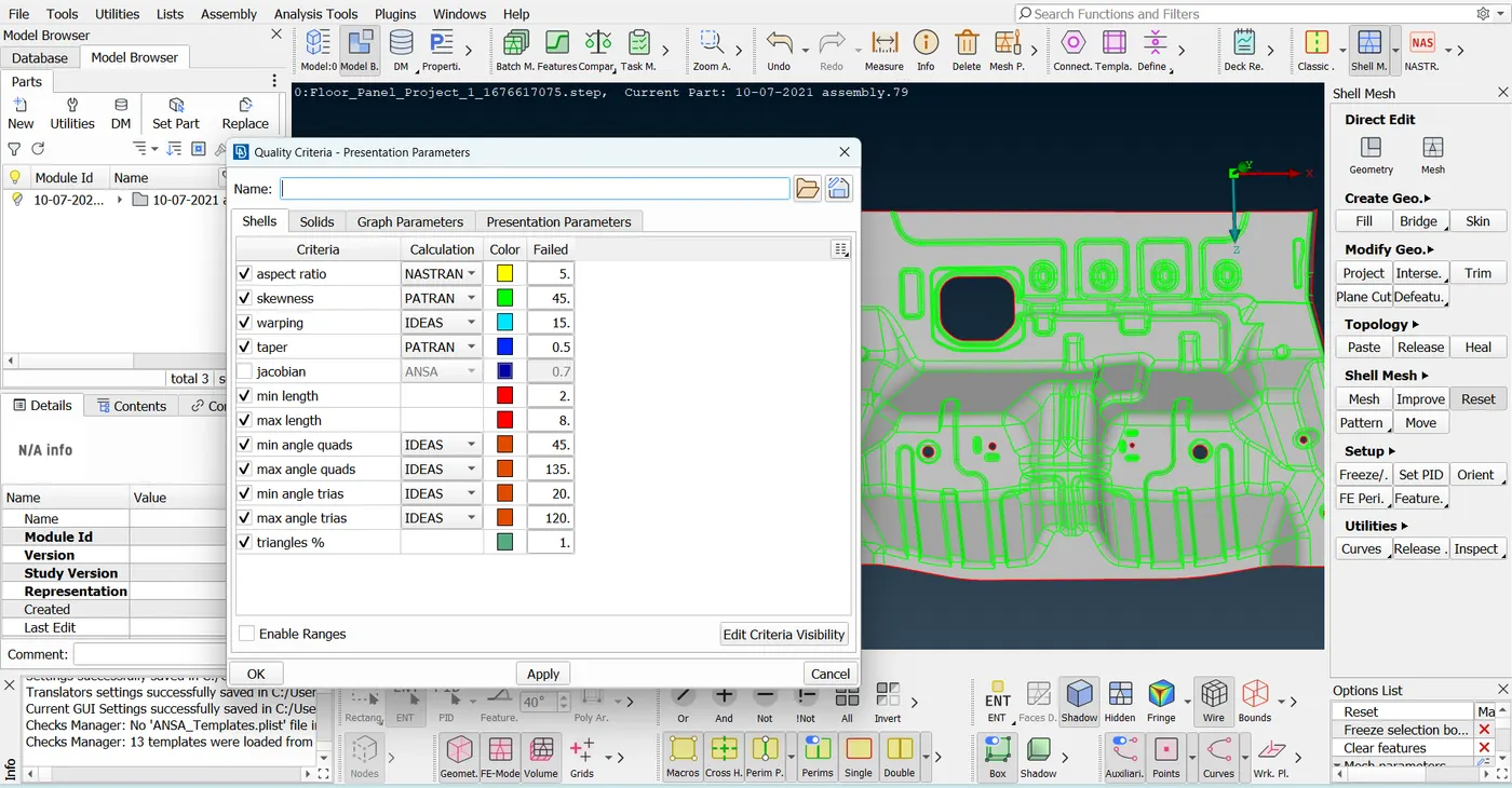
Quality Criteria :
Aspect Ratio: 5
Skewness: 45
Warping: 15
Taper: 0.5
Min. Length: 2
Max. Length: 8
Min angle Quad: 45
Max angle Quad: 135
Min angle Tria: 20
Max angle Tria: 120
Tria%: 10
Procedure Followed:
Step 1: Imported the .step file which is provided from skill lync platform.
File-Open-floor panel .step
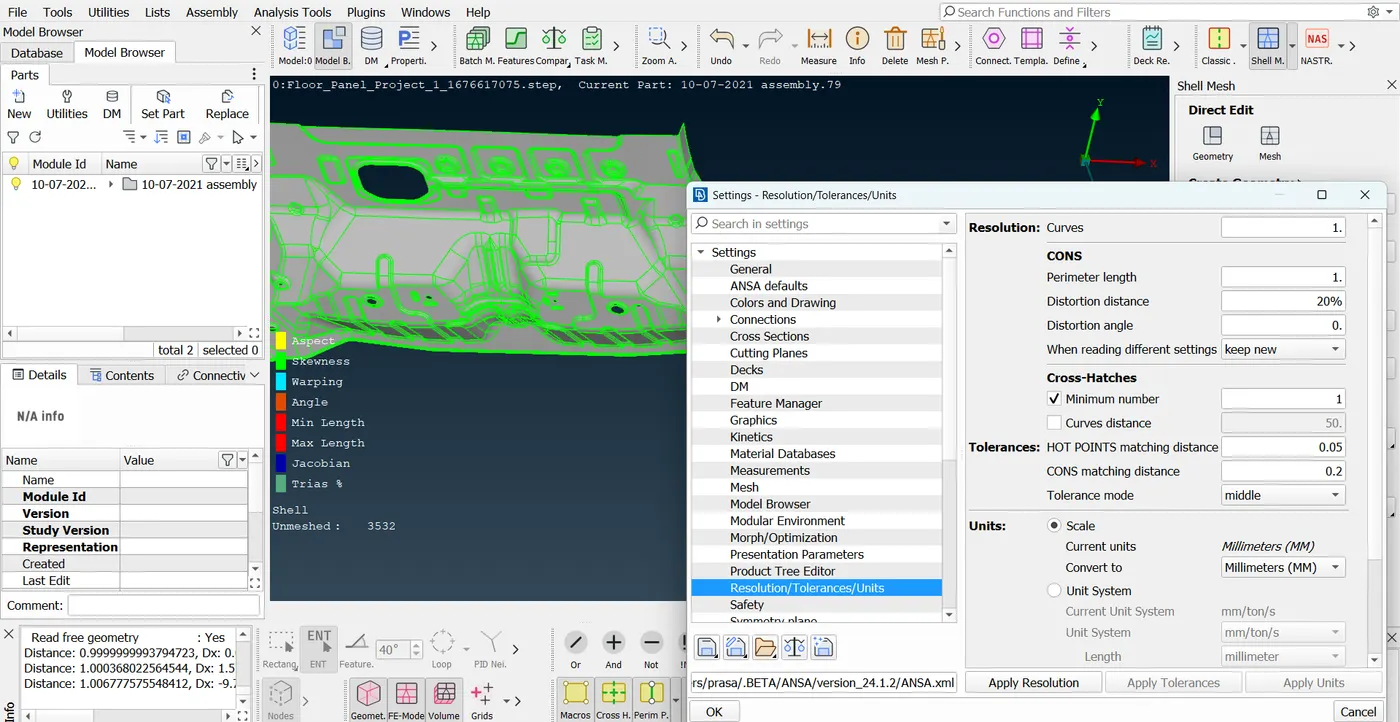
Step 2: For better capturing the geometry, i adjusted the settings to Curve= 1, Perimeter length= 1. if we do so that will help to identify the errors easily and we can fix the errors easily.
Tools- Settings- Settings- General- Resolution/Tolerances/Units- Curves=1, Perimeter= 1.
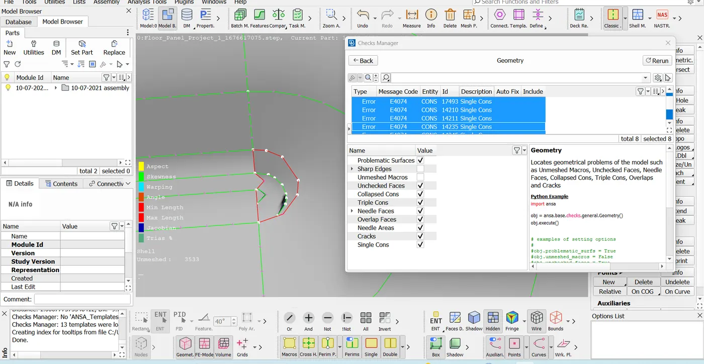
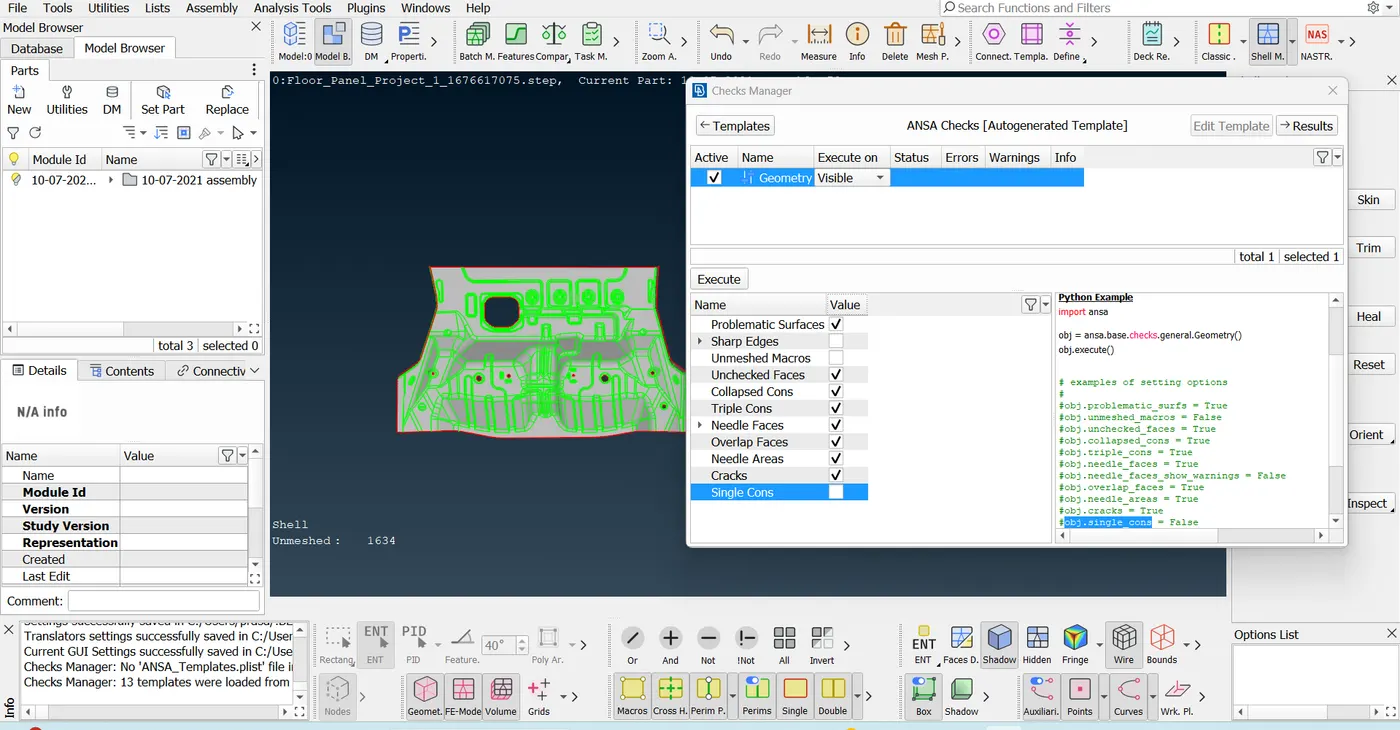
Step 3: After Doing the Resolutions settings then i checked model for geometrical errors. if that geometry having error in it then we can not extract the mid surface using mid option. and it is also necessary to check the model for geometry check up before mid extraction so that the maximum of the errors clear here it self and we will get the error free Mid. When i checked the given model the i get same errors thet shown below with the auto fix option the
Tools- Checks- Geometry checks
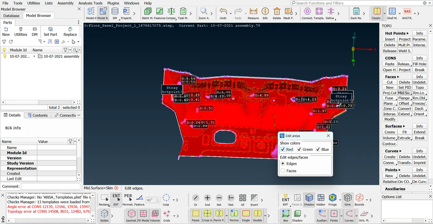
Step 4: The given model is the solid sheet metal model so first i converted the model to shell model or mid surface model that is i extracted the Mid for the given Model. after extracting the mid i have checked the mid surface for geometry check same as i had i as before but here i deactivate the single cons. as shown below figure.
Topo- Mid.surf- Skin
Step 5: After mid surface extraction i have save the given quality criteria then i reset the grid distribution that is perimeter length to 5 and applied the mesh to given model and where ever their is need of toggling and nodel movement i done that to serves the given quality range.
Shell Mesh- Shell Mesh- Reset
Value Addition
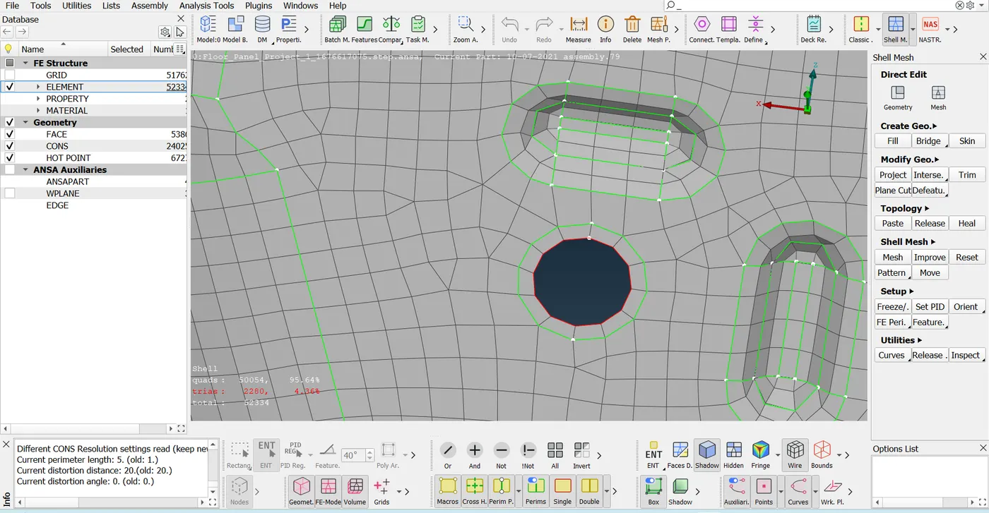
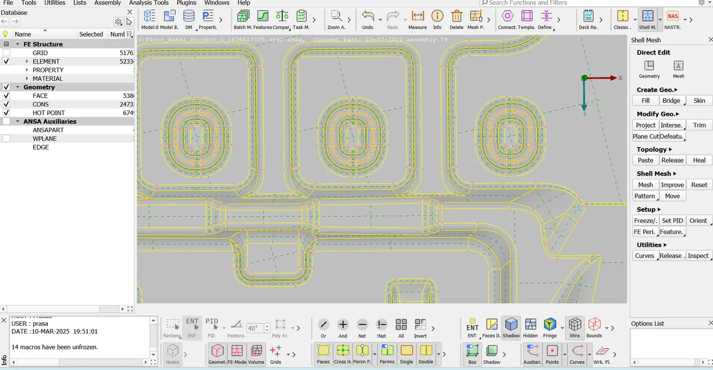
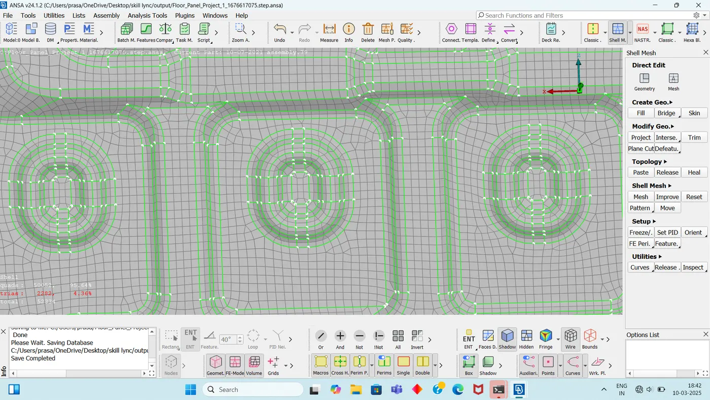
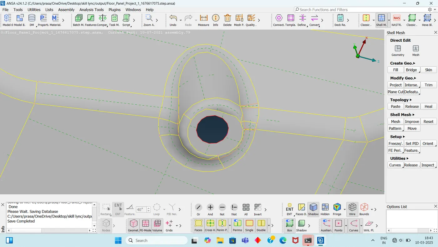
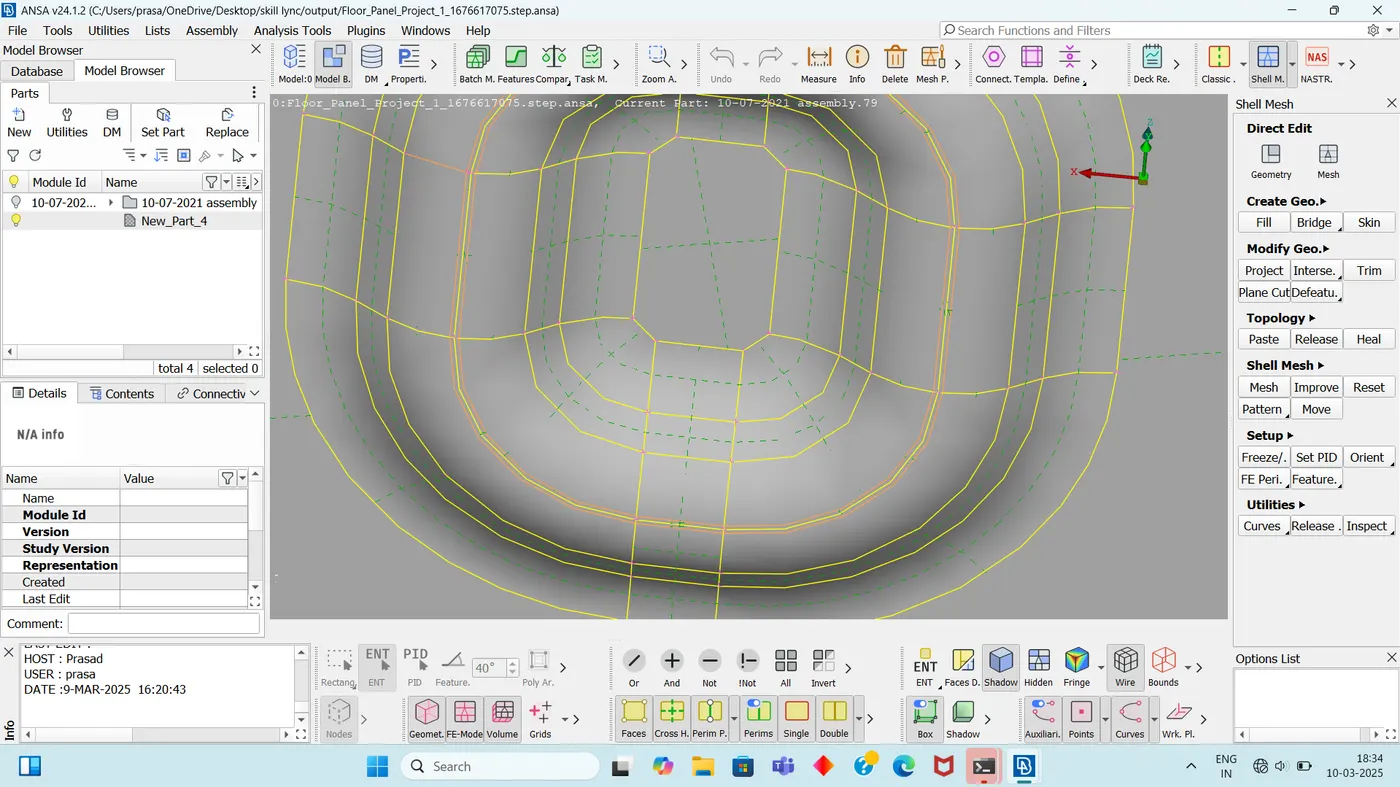
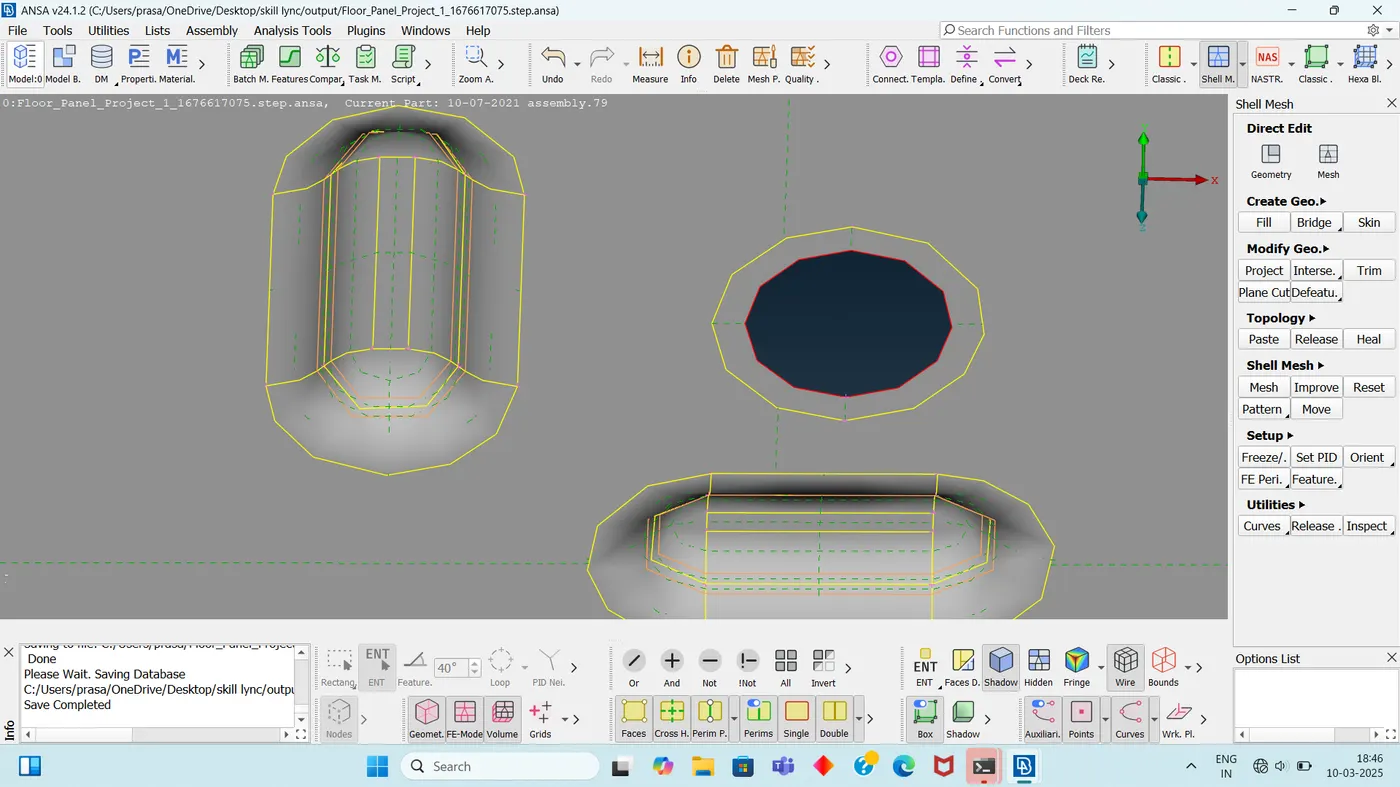
1. I have Created the Washer zone near the hole zone and passed the one row of elements.
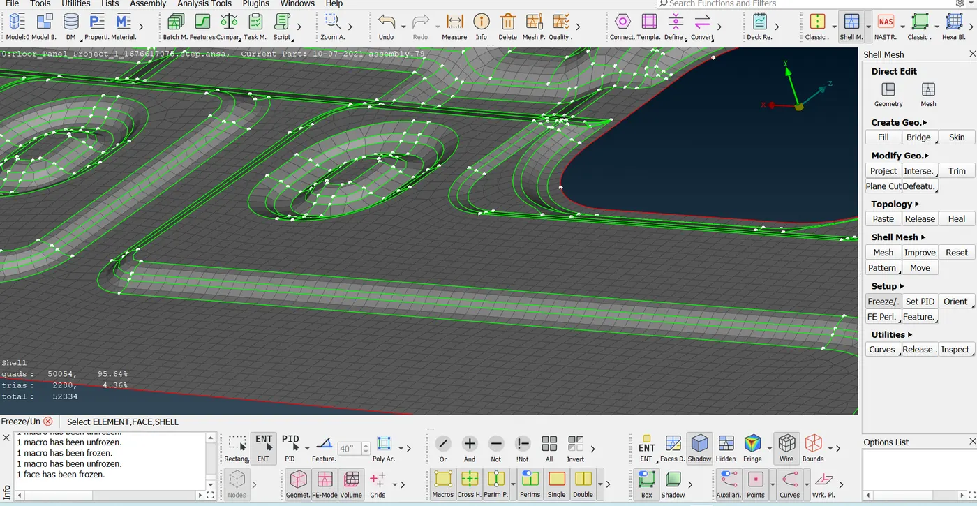
2. In the Fillet region of 2mm-5mm width i have passed the two row of elements for better capturing the fillet region.
3. For the similar features i have done the same type of toggling and i have applied the similar mesh. to give the similar results after simulation.
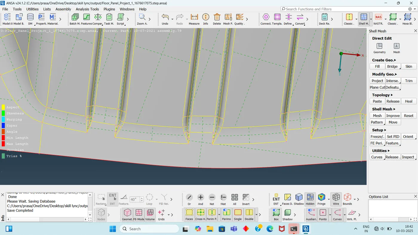
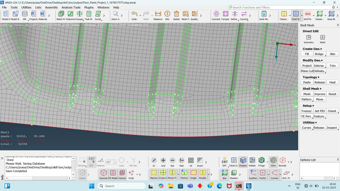
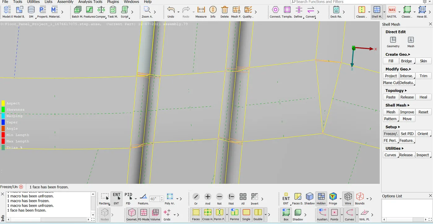
4. Through out the model where ever the quality failing to fix the quality or to pass for the quality criteria i have done the nodel movement of 0.1 to 0.25 mm on each side (up to 5mm ) as shown below.
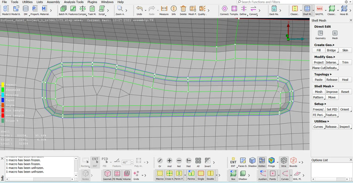
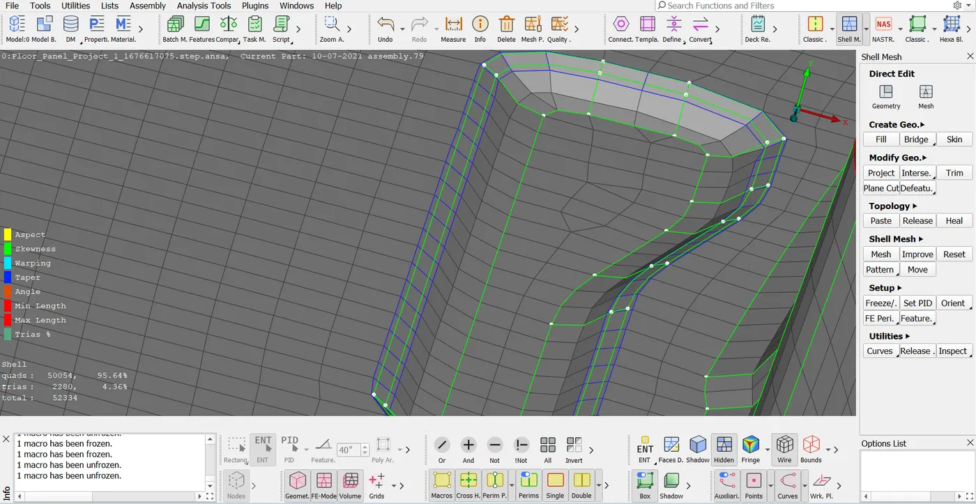
5. The quality errors falling for more than 0.5mm then i have toggled the feature line that is also in the flow of the feature line not on the opposite to the flow of feature line as show in below.
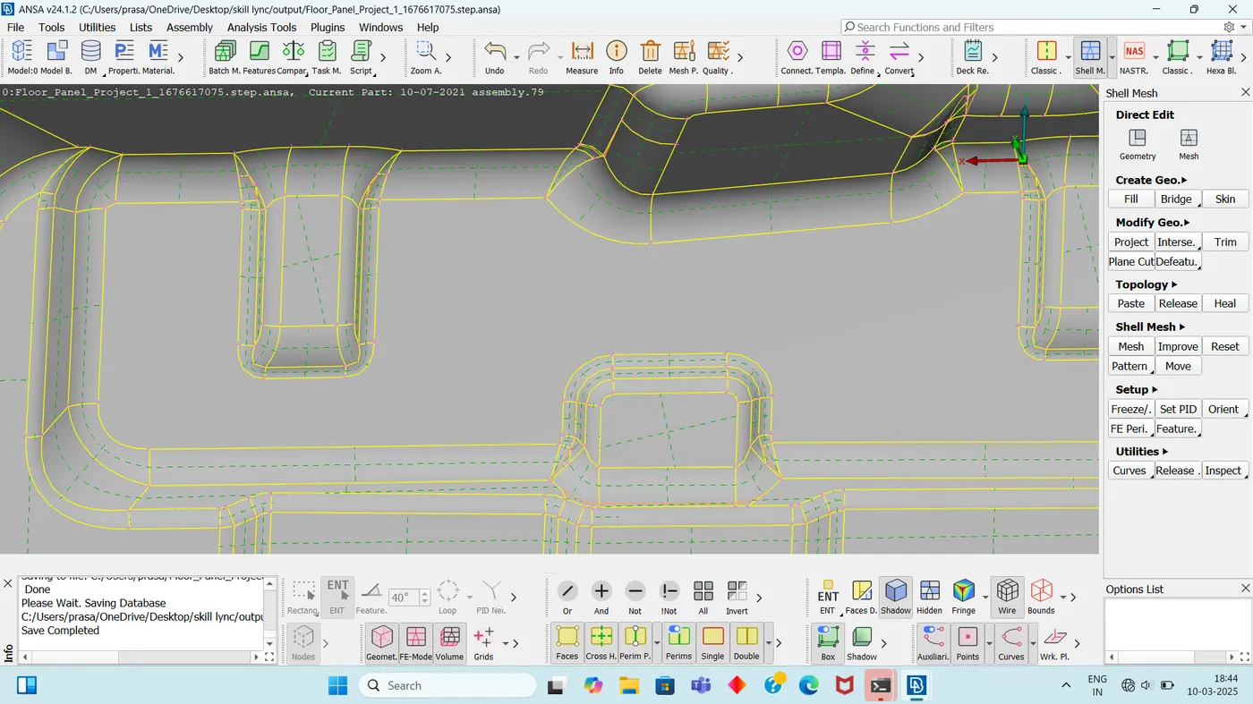
6. When ever the elements falling in between the feature lines and where ever it is possible to take the common feature line i have done that and i have removed the original.
7. We all Know that the triaes are more stiffer and that will effect on the simulation results so i have not placed the touching tria into the model and also the tria touching through the feature line i have removed but it is not possible to remove the all tria that are touching each other or touching to the feature line.
(For better representation of tria i sated the tria % for 1%)
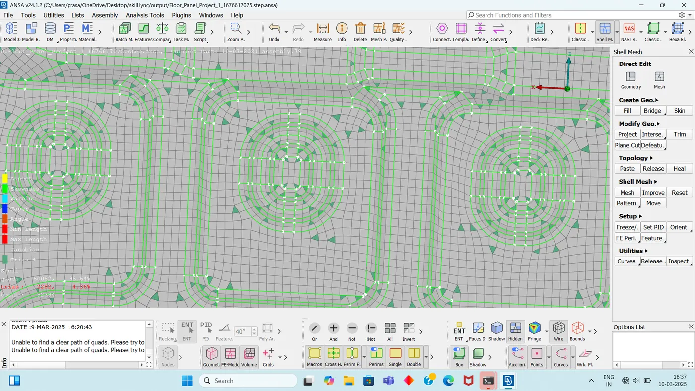
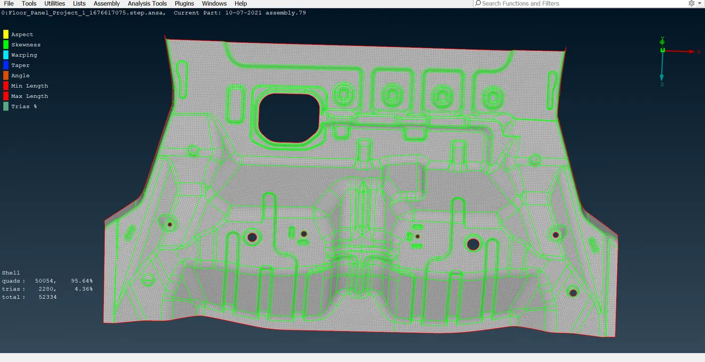
Final Meshed Model considering the all Quality Criteria
Declaration: I hereby that declare that the above details are true to the best of my knowledge. i have successfully competed the meshing of given model while meeting the quality criteria and finishing it before the deadline