Project 1 - Meshing of Floor Panel
Objective: To perform geometry cleanup, extract mid-surface and perform 2D meshing using the given quality criteria on the given Floor panel model
Procedure:
The given Floor panel model falls under the category of sheet metal components. So 2D meshing should be performed on the given component in the pre-processing stage.
The procedure consists of three steps.
1. Geometry clean up
2. Extraction of mid-surface
3. 2D Meshing
1. GEOMETRY CLEAN UP
i. Import the IGES file to ANSA and open the CAD model.
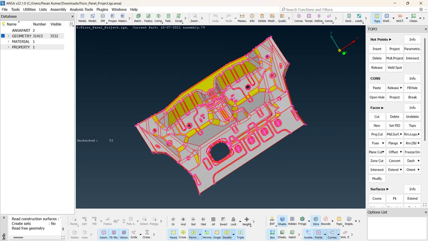
Figure 1: CAD model of the given Floor Panel
ii. After importing, perform topology as the initial step. Faces >> Topo
iii. Ensure that the material for the component is defined.
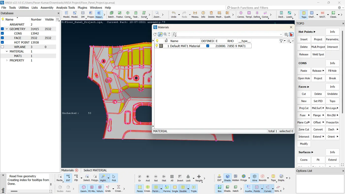
Figure 2: Material ID defined
iv. Go to geometry checks manager and perform checks geometry to find the topology errors.
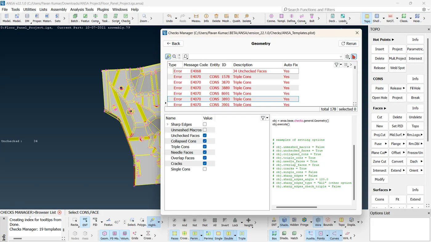
Figure 3: Geometry checks manager showing topology errors
v. Perform geometry checks in a series of steps and clean up the geometry as per the error.
A few errors are fixed using the autofix option.
Single cons are pasted using the Cons option. Cons>>Paste
Triple cons are fixed by the release cons option.
Unchecked faces need to be fixed by generating new faces in the areas where the surface is missing.
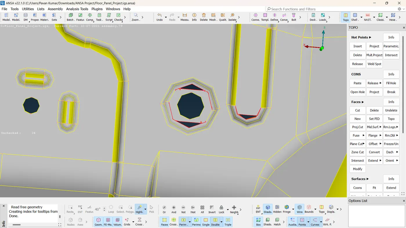
Figure 4: Topology error showing cracks between faces
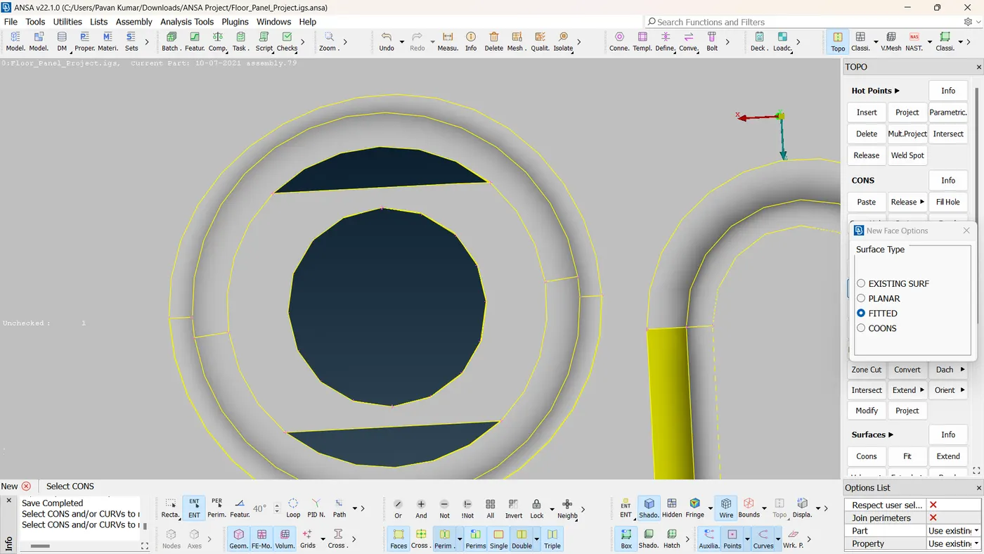
Figure 5: Rectified topology error
vi. Similarly, all the errors are rectified and geometry is cleaned up.
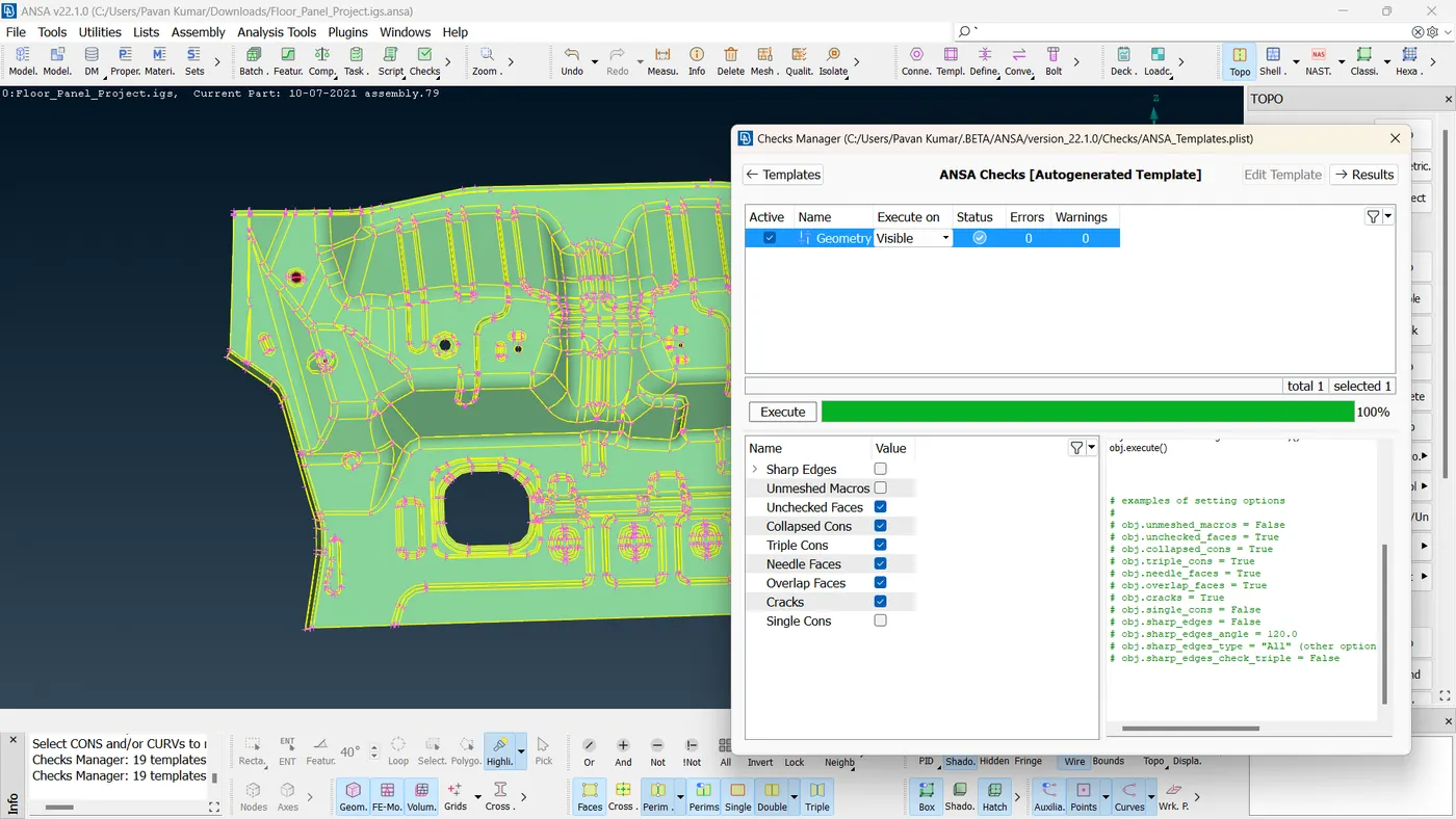
Figure 6: Checks manager showing 0 topology errors
2. MID SURFACE EXTRACTION:
To extract the mid-surface, first measure the thickness of the model.
Utilities>>Measure

Figure 7: Thickness of the floor panel
Since the thickness of the component is 1.0 mm, the mid-surface exists at half the distance measured from the top surface and half the distance measured from the bottom surface.
So the off-set distance is 1/2 = 0.5mm
Mid-surface is extracted using the manual mid-surfacing procedure.
Faces>>Offset
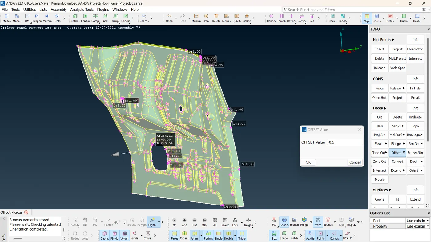
Figure 8: Offset value given 0.5mm
Select the offset option, and select the faces. Input offset distance and offset direction.
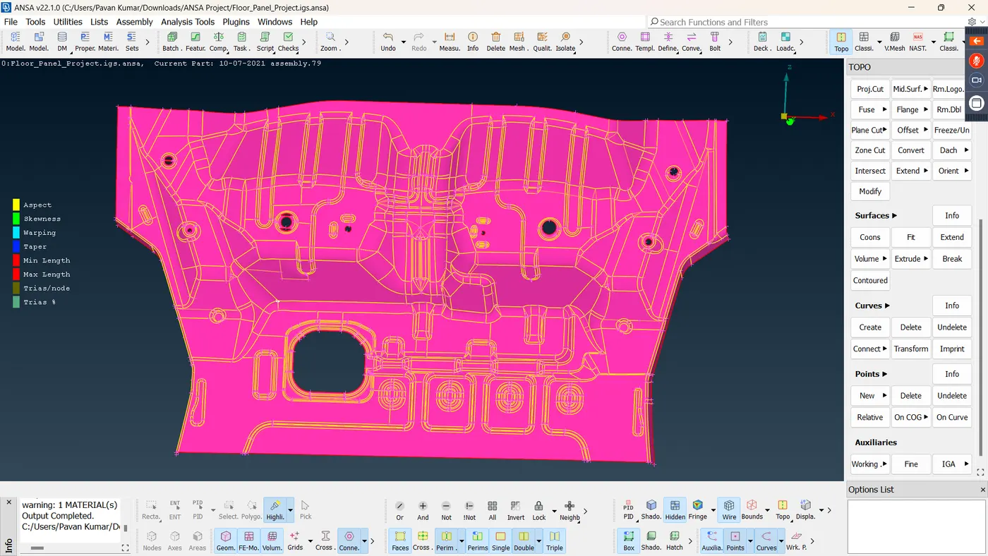 Figure 9: Mid Surface
After extracting the mid-surface, assign property ID to the mid-surface using assign PID and ensure that the material is defined.
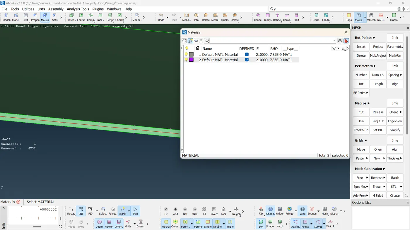
Figure 8: PID is assigned and Material is defined
3. 2D MESHING OF THE MID SURFACE AND ASSIGNING THICKNESS
The given Floor panel model is a sheet metal component. Hence, 2D meshing has to be performed on the mid-surface.
To mesh the component, the element quality criteria have to be defined.
The element size is given as 5.
Perimeters >> Length >> Perimeters >> set the length to 5
Using the measure command, measure the distance between the nodes on the perimeter at various locations and ensure that the distance between the nodes meets the defined length.
Define the element quality criteria as per the model requirement. The element quality criteria can be defined by using the Utilities command.
Utilities >> Quality Criteria
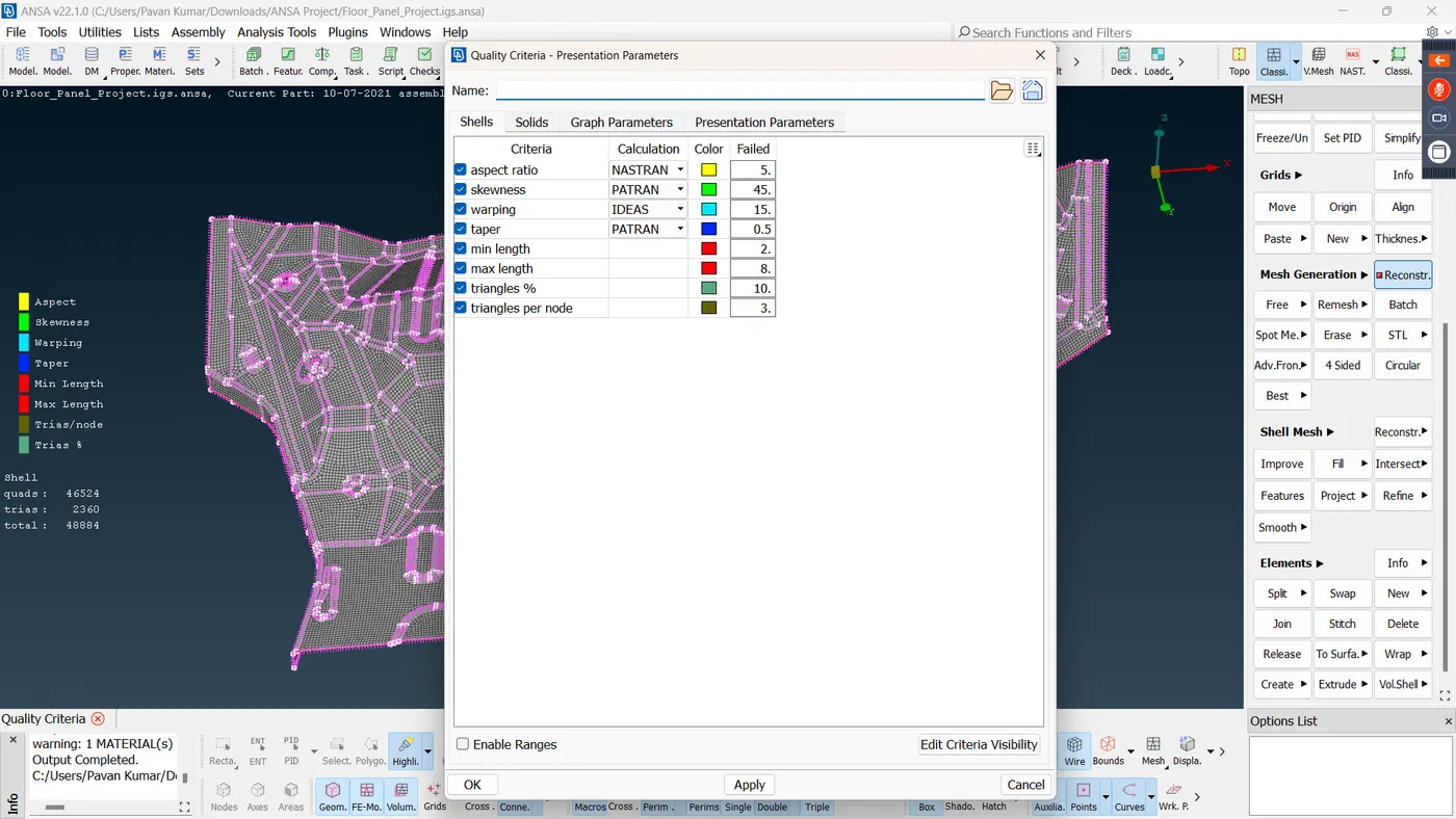
Figure 9: Element quality criteria defined as per the requirement
After defining the element quality criteria, start meshing.
From the modules panel, switch to the Classic meshing module. This module consists of all the meshing tools.
In the meshing module, using the mesh generation command start meshing the component.
Mesh Generation >> Best
If the obtained best mesh has any issues, the mesh can be reconstructed using the reconstruct command.
Shell mesh >> Reconstruct
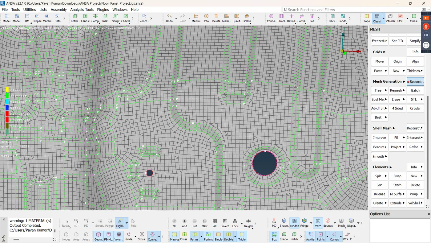
Figure 10. Meshed surface
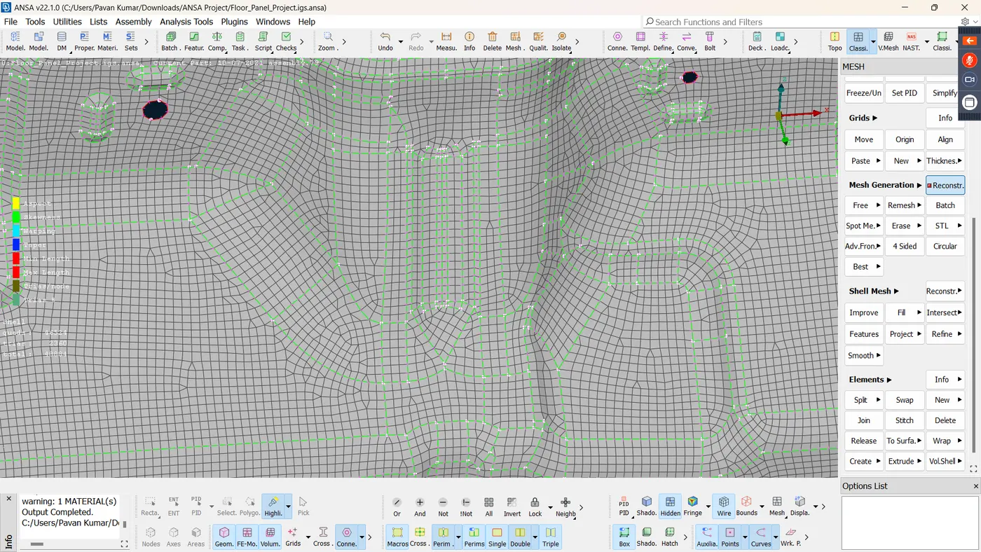
Figure 11: Meshed surface
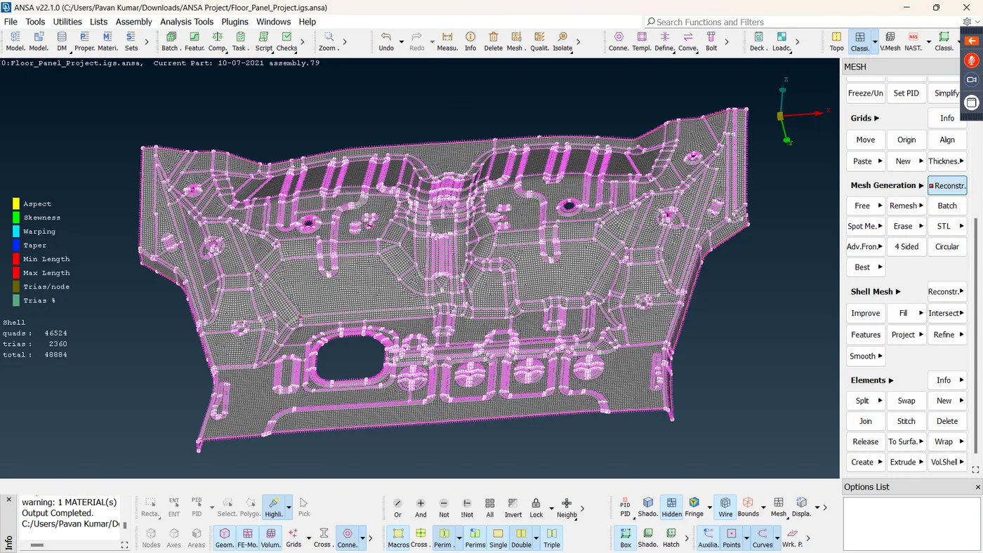
Figure 12: Completely Meshed component
After meshing the component, assign thickness to the meshed component.
For assigning thickness, select the property ID of the component.
PID >> Thickness
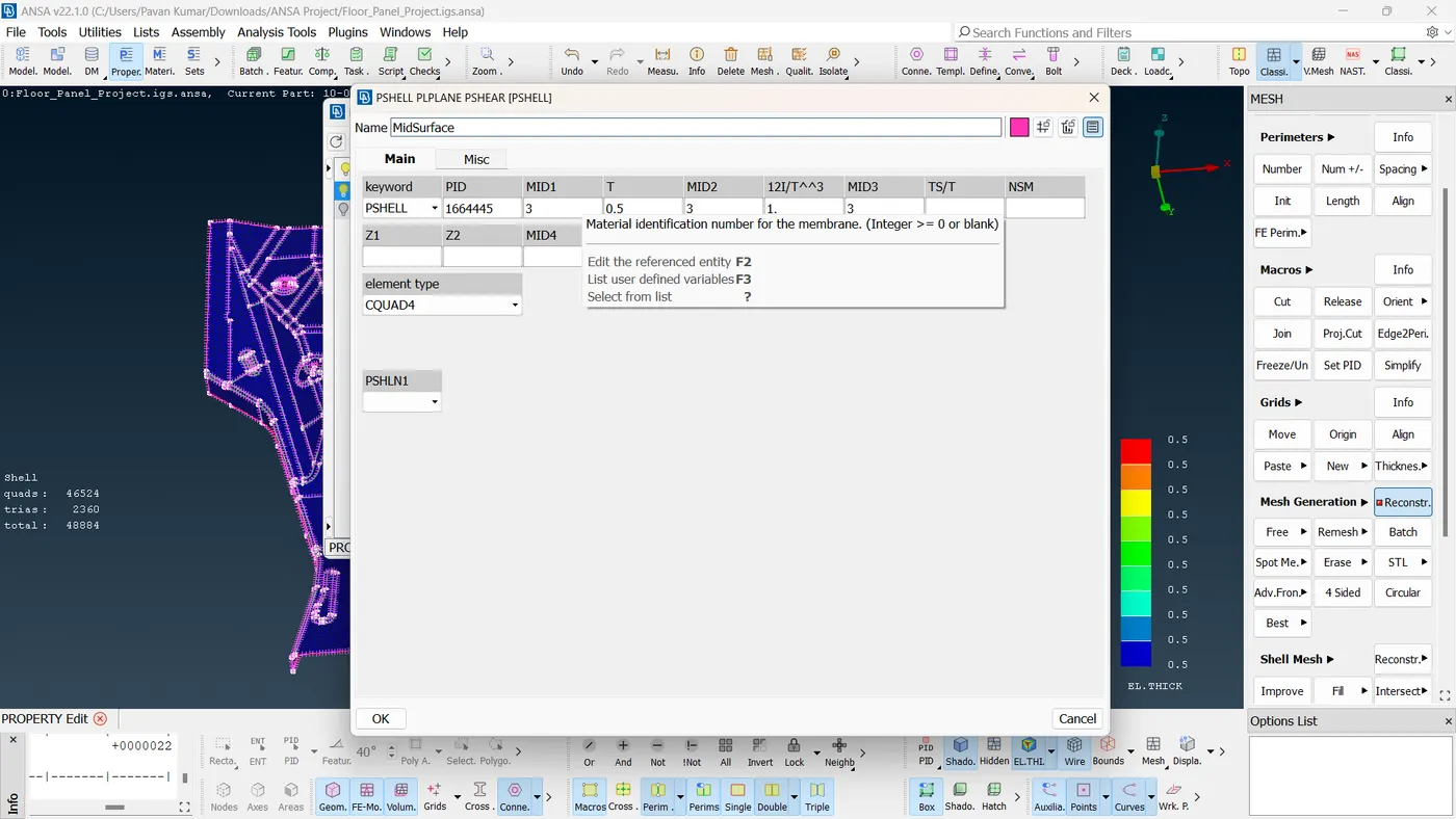
Figure 13: Thickness assigned
LEARNING OUTCOME:
1. I have understood the ANSA GUI and various commands in ANSA
2. I have learned to perform geometry cleanup to rectify topology errors.
3. I have learned the manual mid-surfacing procedure for extracting the mid-surface of a sheet metal
4. I have learned about element quality criteria and their importance in obtaining a good-quality mesh.
5. I have understood the 2D meshing procedure and why 2D meshing is performed on sheet metal components.