Project 1 Mechanical design of battery pack
Battery pack capacity: 18 kWh
Cell: ANR26650M1-B
Prepare a detailed battery pack drawing along with its enclosure. State your assumptions.
OBJECTIVE:
To Prepare a detailed battery pack drawing along with its enclosure with ANR26650M1-B by a capacity of 18 kWh.
ANR26650M1-B is a Nano phosphate high power lithium-ion cell which is made by lithium iron phosphate (LiFePo4). This is more power and have high energy than other cells and lower impedance it has high efficiency with more safety precautions also having long life. It has wide range of SOC with less losses which leads to less discharge for long range with lighter weight. These cells have low-capacity loss and impedance growth over time as well as high usable energy over wide state of charge range.
It is widely used in all areas which have necessity of high power and energy as, transmission and distribution, grids, power plants, EV and HEV vehicles, military machines and vehicles. And it uses also in system back-ups, industrial robotics, medical devices etc.
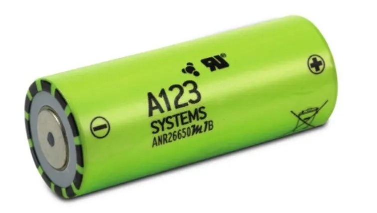
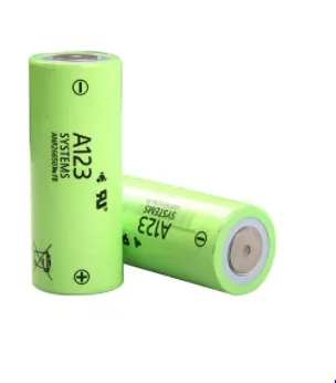
The view of the ANR26650M1-B is as shown below, by the A123 systems manufacturer.
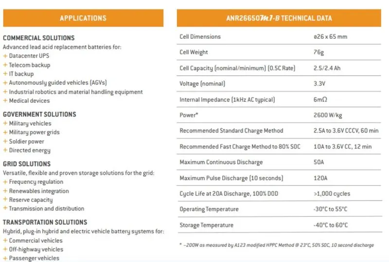
Battery Details are shown below as per data sheet,
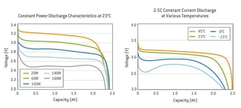
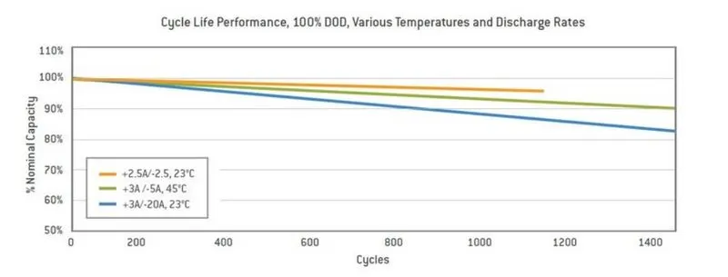
If we observe the characteristics of the ANR26650M1-B by different conditions like constant power discharge characteristics, constant current discharge at various temperatures, and some other as shown below,
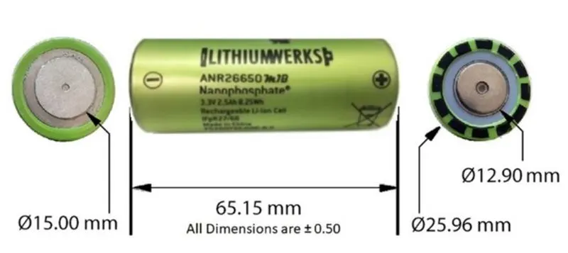
Design of the ANR26650M1-B cell with dimensions as shown below,
Battery design Calculations:
Nominal Rating:
- voltage: 3.3 volts
- capacity: 2.5Ah
- energy: 8.25Wh
- specific power: 2600W/kg
- impedance(1KHz AC typical): 6 mΩ
- cell type: 26650 lithium-ion power cylindrical cell.
Discharging:
- max.continuous discharge: 50A
- max pulse discharge current > 50% SOC (10sec): 120A
- minimum voltage: 2 volts
- temperature: -30 to 55 degree celsius
Charging:
- recommended std. charge: 2.5A
- max charge rate: 10A
- max pulse charge current<50% SOC (10sec) : 25A
- float voltage: 3.45 volts
Mechanical parameters:
- diameter: 25.96 +/- 0.5 mm
- length: 65.15+/- 0.5 mm
- mass: 76g
* Calculation as per assumptions: 18 kWh battery pack.
The calculation for designing an 18 KWh battery pack basically 18 KWh is the energy required to achieve the vehicle in its proper range and it depends on the voltage(V) and amp-hr capacity(Ah).
1] single cell energy(Wh) [the value of single cell energy is used to calculate the total energy of the battery pack]:
single cell energy(Wh)= cell capacity(Ah)* cell voltage(V)
= 2.5Ah *3.3V
= 8.25 Wh
2] single cell volume calculation:
single cell volume = pi(r^2)*h
= 3.14(0.013^2)*0.065
= 0.03451 m^3
3] single cell energy density:
A] volumetric energy(Wh/m^3) = single cell energy / volume of each cell
= 8.25Wh / 0.03451 m^3
= 239.0611 Wh/m^3
B] gravimetric energy(Wh/kg) = single cell energy / single cell mass
= 8.25Wh / 0.076 kg
=108.5526 Wh/Kg
Calculation of high voltage battery pack:
For the design and calculation of the battery pack here, I assume a vehicle to achieve 200km in an 18 KWh battery pack also I assume 145.2 nominal voltage for series connection.
we assume that,
vehicle range = 200 Km
battery pack capacity = 18.1210KWh
now,
4] we will calculate per Km average energy requirement = 18120.96 (Wh)/200 (Km)
= 90.60 Wh/Km
Therefore,
battery pack total energy = average energy * km
= 90.60Wh * 200km
= 18120.96 Wh
let's assume nominal voltage for series connection= 145.2 V basically this depends upon the motor power, we can decide the value according to the motor.
5] number of cells connected in series = nominal voltage of series connection/nominal voltage of a single cell
= 145.2V/ 3.3V
= 44 cell
44 cells will be connected in a series connection to provide a proper voltage.
6] energy for battery pack(Wh) = number of cells connected in series * single cell energy
= 44* 8.25Wh
= 363 Wh
7] number of cells connected in parallel = battery pack total energy(Wh)/energy for battery pack(Wh)
= 18120.96 Wh/363 Wh
= 50 cells
50 cells will be connected in a parallel to provide a proper capacity power.
8] battery pack total energy(Wh) = no. of cell connected in parallel * energy for battery pack
= 50* 363 Wh
= 18.150 KWh
9] battery pack capacity(Ah) = no. of cell connected in parallel * single cell capacity(Ah)
= 50*2.5 Ah
= 125 Ah
the value of battery pack capacity is used for the total power required by the vehicle.
10] The total number of cells for battery pack = no. of cells connected in parallel * number of cells connected in series
= 50*44
=2200 cells
2200 cells will be used to make a complete battery pack.
11] mass of battery pack = total number of cells for battery pack * mass of single cell
= 2200 * 0.076 kg
= 167.2 kg
167.2 kg is the total weight of cells connected in parallel and series
12] total volume of the battery pack = total number of cells for battery pack * volume of single cell
= 2200 * 0.0345 m3
= 75.9 m3
75.9 m3
is the volume occupied by the total cells used in the battery pack.
13] cell peak current(A) = C rate(max pulse charge current)* single cell capacity
= 20* 2.5
= 50A
14] battery pack peak current(A) = cell peak current(A) * no. of cell connected in parallel
=50*50
= 2500A
15] battery pack peak power(W) = battery pack peak current(A) * voltage of series connection
= 2500 A * 145.2
= 363 KW
16] cell continuous current(A) = C rate(max continuous charge current)* single cell capacity
= 10* 2.5
= 25A
17] battery pack continuous current(A) = cell continuous current(A) * no. of cell connected in parallel
= 25*50
= 1250 A
18] battery pack continuous power(W) = battery pack continuous current(A) * voltage of series connection
= 1250 A * 145.2
= 181.5 KW.
Building steps of the battery pack:
Cylindrical cells:
Cylindrical cells are the most common cell type in use today. This design allows for better automation processes and techniques that increase consistency and lower cost.
Compared to prismatic cells, cylindrical cells can be produced much faster so more KWh per cell can be produced every day equaling lower $ per kWh. The electrodes in a cylindrical cell are wound tightly and encased in a metal casing, This minimizes electrode material from breaking up from the mechanical vibrations, thermal cycling from charging and discharging, and mechanical expansion of the current conductors inside from thermal cycling. Many cells are combined in series and in parallel to increase the voltage and capacity of the battery pack. If one cell goes bad, the impact on the entire pack is low. With prismatic cells, if one cell goes bad it can compromise the whole battery pack.
Series Strings :
Cells combined in series strings can achieve higher operating voltages by connecting the positive terminal of one cell to the negative terminal of the next cell. Connect strings of series cells using their current collection tabs like that illustrated in Figure -
Parallel Strings :
Cells combined in parallel strings can achieve higher operating capacities by connecting like-polarity terminals of adjacent cells. Connect strings of parallel cells using their current collection tabs like that illustrated in Figure -
Nickel Strips :
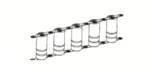
Conductive metal strips are spot welded between all the cells of an electric bicycle battery pack. Nickel is the material of choice due to its low relative resistance and ease of spot welding. Steel is cheaper than nickel, which is why many vendors sell nickel-coated steel strips. It brings the cost down, but at the expense of pack health.
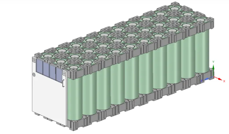
General Steps to Design a practical Battery Pack :
Step 1 -
Design of cell holder (Bottom and Top) :
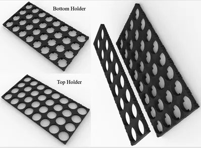
The main function of a battery holder is to keep cells fixed in place safely and securely also it is used to keep cells in a proper arrangement so that there will be a decrease in mechanical vibration, and have a better thermal runway in between the gaps of the cell. Most of the cell holder is made up of polypropylene or nylon bodies rated for 80–100 °C.
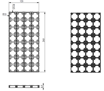
Battery Pack holders
Step 2 -
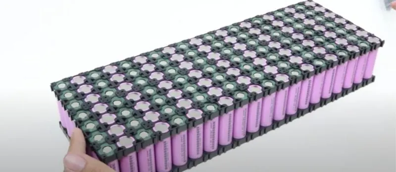
Inserting cells inside the holder (Bottom and Top) :
Insert the cells inside these connectors with positive and negative poles kept alternatively in adjacent rows.
Step 3 -
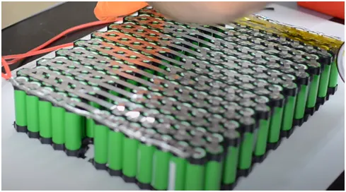
Spot welding :
Spot weld with nickel strips to make a series connection between the cells as shown -
Step 4 -
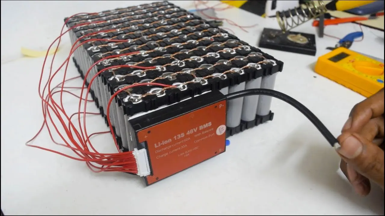
Install BMS for the battery pack as shown -
Step 5 -
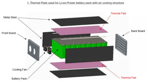
Install cooling structures for air cooling/ liquid cooling as shown
Step 6 -
Install the battery pack inside the enclosure as shown -
Enclosure for battery packs :
There are different types of enclosures available for the battery pack. A few are explained below. The main features required for EV battery enclosures are :
- Lightweight
- Shock and Vibration-proof
- Fire protection
- Prevent Electromagnetic radiation
- Low cost
- Aluminium sheet battery enclosure.
Aluminium's inherent properties — corrosion resistance and recyclability — make the metal attractive in electric-vehicle manufacturing. The enclosure regulates thermal conductivity by helping to cool and heat the battery cells.
Using aluminium to enclose a lithium-ion battery pack in an EV can reduce weight by about 50 per cent.
Weight savings translates into a longer driving range, a major challenge for the competitiveness of electric vehicles.
The lightweight aluminium translates into a lower cost per weight at mass-production volumes.
CONCLUSION:
For the given cell model of ANR2665031-B, we have prepared a detailed battery pack design along with its enclosure and Stated my assumptions.