Project 1 Mechanical design of battery pack
Battery pack capacity: 18 kWh
Cell: ANR26650M1-B
Prepare a detailed battery pack drawing along with its enclosure. State your assumptions.
ANS:
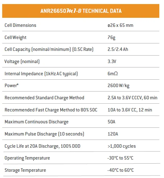
Specification of Cell ANR26650M1-B. Detailled Specification sheet attached.
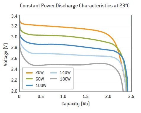
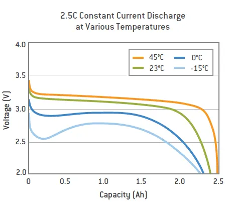
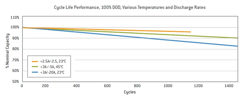
Discharge Characterstics:
EV design - Battery calculation:
Assumptions:
Battery energy = 18 kwh
Voltage (to run the vehicle) = 400V
(i) Energy = 18 kWh
(ii) Number of cells (N) = energy / (nominal voltage*capacity)
N = 18000 / (3.3*2.5)
N = 2182
We need a minimum of 2182 cells to get 18 kWh energy, now based on that, we need to decide configuration – series and parallel.
In series configuration capacity remains the same and voltage will be the sum of individual cell voltage.
In a parallel configuration, the voltage remains the same and capacity accumulates.
And we assumed 400 Volts are need to run the vehicle.
The nominal voltage of one cell is 3.3 V
Number of series cells required to produce 400 V (Ns) = voltage required / nominal voltage of one cell
Ns = 400 / 3.3
Ns = 121.21 = 122
122 cells are connected in series will generate 400 voltage and the capacity of the whole module will be 2.5 Ah
Now we need to find the number of cells which will be connected in a parallel configuration
Np (cell in parallel) = total cell / Ns
Np = 2182 / 122
Np = 17.8 = 18
Hence we take 18 cells for each parallel row, although it is exceeding the required capacity, that is negligible.
Cell architecture = 122 Series and 18 Parallel = 122S18P
(iii) Battery capacity:
We know parallel configured cell multiplies individual cell capacity so,
Capacity = parallel cell row*individual cell capacity
Capacity = 18 * 2.5
Capacity = 45 Ah
(iv) Current supplied by the battery
We have already calculated battery capacity which is 45 Ah means it is going to supply 45 A current per hour. which can be considered as C-rate.
(v) Range:
Let’s powertrain energy consumption = 100 Wh/km at 70% powertrain efficiency
Range = Capacity / energy consumed per kilometre
Range = 18000 / 100
Range = 180 km
So,our vehicle will be able to cover around 180 km with current parameters.
(vi) Internal Resistance of Battery:
The entire resistance encountered by a current as if it flows through a battery from the negative terminal to the positive terminal is known as internal resistance of battery.
(vii) Battery Dimensions:
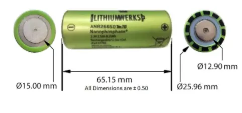
ANR26650 cell has 26mm diameter and 65mm height. On the basis of that we need to decide battery size of battery casing.
Length of casing (L) = number of cells at series*(cell diameter (26) + margin at both side of cell (4)) + clearance at side (diameter of edged cell + margin)
L = 122*30 + 60
L = 3720 mm
Breadth of casing (B) = number of cells at parallel*(cell diameter (26) + margin at both side of cell (4) + clearance at side (diameter of edged cell + margin)
B = 18*30 + 60
B = 600 mm
Height of casing (H) = 65+35 (Height of cell + margin for wiring ,Cell holders and metal strips)
H = 100 mm
(viii) Weight of battery pack
Cell weight = 76g
Number of the cells = 2182
Battery pack weight (W) = cell weight*number of cells + weight of accessories
W = 76*2182 + 4.5 = 165.8 + 4.5 = 170.3 kg
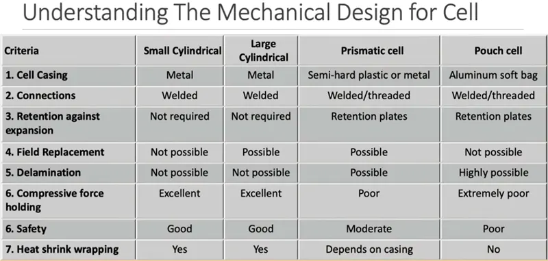
Mechanical Design Requirement:
- The Battery pack need to be mechanically stable.
- It should take care of the vibration and shock that is expected while being installed in the vehicle. AIS-048 and un-38.3 could be referred for the same.
- It should be safe in case of drop. IEC62133 could be referred
- Cell should not experience higher temperature. Specially in the hot climate.
- All the cell in the battery pack should experience same temperature.
- Battery pack may have active cooling available or passive cooling available or no cooling provision available.
Important Considerations:
- Material Selection
- Base plate design for individual cell accomodation
- Cell movement consideration in control
- Uniform pressure over cell surface
- Material cost optimization
- Outer case design for overall protection.
- Bus-bar designing.
- Packaging constraints.
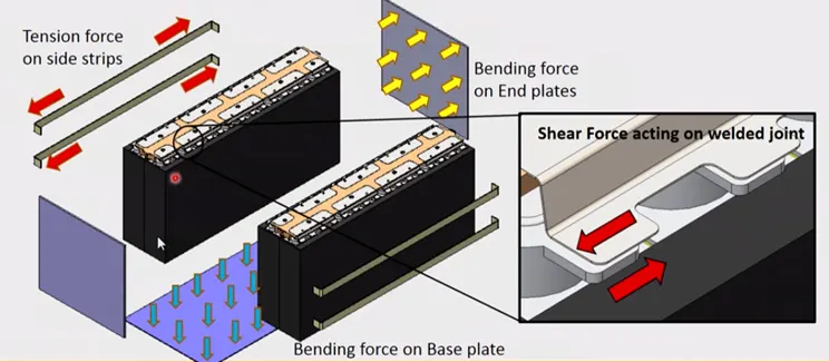
Forces on Battery Pack:
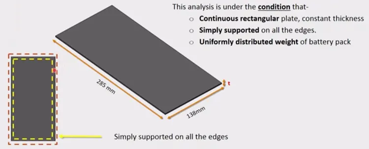
Base plate thickness Calculation:
Cylindrical battery pack assembly equipment:
| Product Name | Description |
| Automatic Cylindrical Battery PVC Heat Shrink Wrapping Machine |
Film speed:50~70PCS/MIN Film precision:±0.1MM |
| 512 Channel Battery Tester | 5V 2A/3A/5A/6A 512 Channel Battery Testser optional |
| Battery Labling Insulation Paper Sticking/Pasting Machine |
Sticker Matrials:Barley paper or PVC Barley paper Maxium 350mm;Scroll Internal Diameter 72-75MM |
| Battery Sorting Machine | (5/6/9/11/13/22 Channel Battery Sorter optional) Data record funtion is selectable |
| Manual Spot Welding Machine |
Pneumatic AC Spot Welding Machine (Single Welding Point or Doubel Welding Point) |
| Manual Spot Welding Machine | AC Pedal Manual Spot Welding Machine |
| Manual Spot Welding Machine | AC Pulse Pneumatic Spot Welding Machine |
| Manual Spot Welding Machine | DC Output Spot Welding Machine |
| Manual Spot Welding Machine | 5000A/8000A Pneumatic Inverter DC Spot Welding Machine |
| Automatic Spot Welding Machine | Double Sides Spot Welding Machine |
| 1-24 series or 1-32 series BMS Tester |
Over-discharge Protection Current:0-120A Overcharge Protection Current:0-50A Overcharge/Overdischarge Voltage:0.5-5V |
| Battery Comprehensive Tester |
100V 120A 18650 Battery Pack Comprehensive Tester |
| Aging Machine |
30 V 10A Charging 20 A Discharging Aging Machine |
| Aging Machine | 70 V 5A Charging 10 A Discharging Aging Machine |
| Aging Machine | 100 V 10A Charging 20 A Discharging Aging Machine |
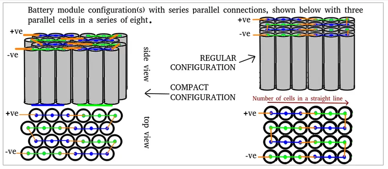
Battery pack series and Parallel arrangement:
Detailed images:
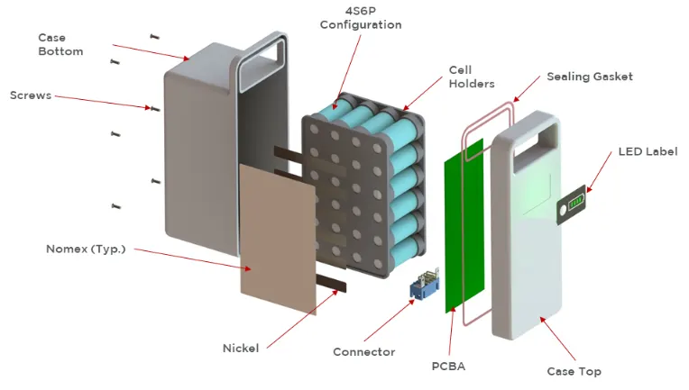
1)Here are the batteries!

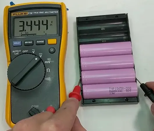
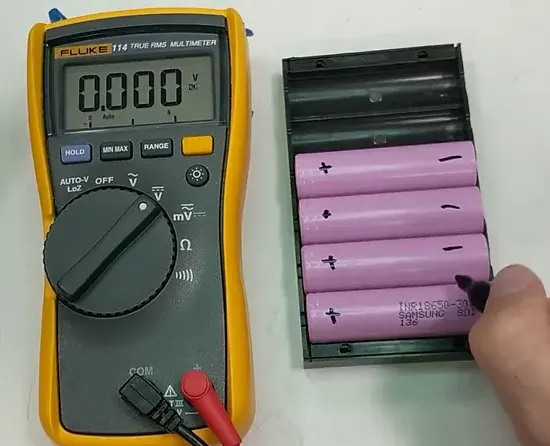
2)Lay the batteries out in a tray, and measure the voltage of each one to make sure that none are dead. The voltage should be between 3 to 4V
3)Mark with a sharpie the positive and negative side of the batteries for easy identification later.
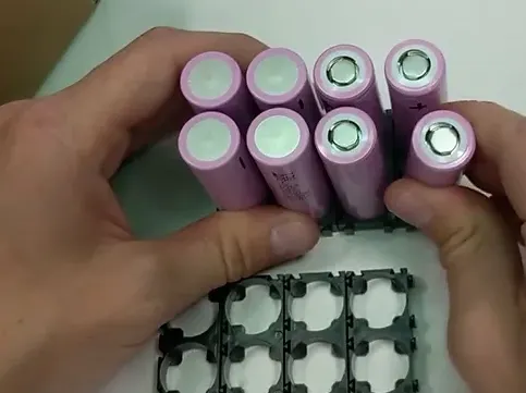
4)Use the handy cell holders to hold all the cells together. Just press fit each cell into the right position.
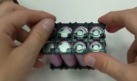
5)Push the plastic cell holders onto the opposite side to finish fully secure the cells together.
6)Using the cell holder as a guide, cut nickel busbars strips to length. Cut the strips just a hair shorter than the width of the plastic holder. The nickel cuts with normal scissors

7)The cells are joined together with a spot welder. Do a few test welds to make sure the nickel strips are well secured to the cell tops. A good weld should hold up to a medium strength tug
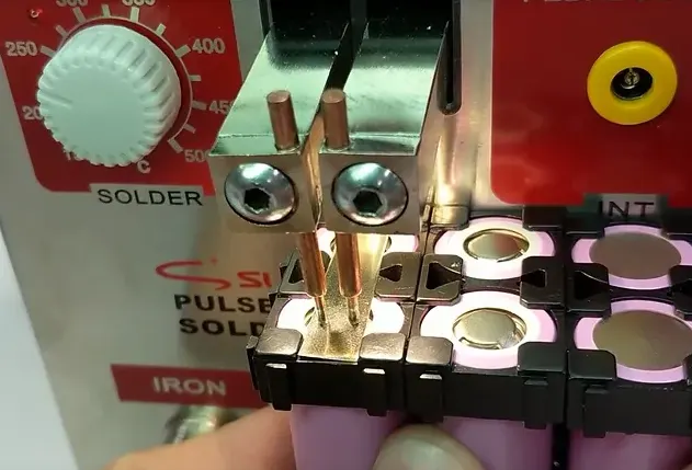
8)Here is a finished section of the battery pack. Cells are joined in parallel first. Each cell should have 2 spot welds (each spot weld makes 2 marks). Do 1 weld on each cell, and wait a minute or so before welding the second spot on the cells in order to minimize heat generation.
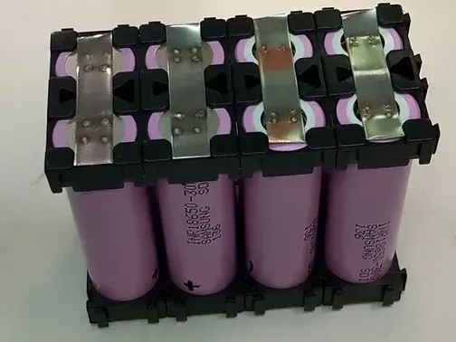
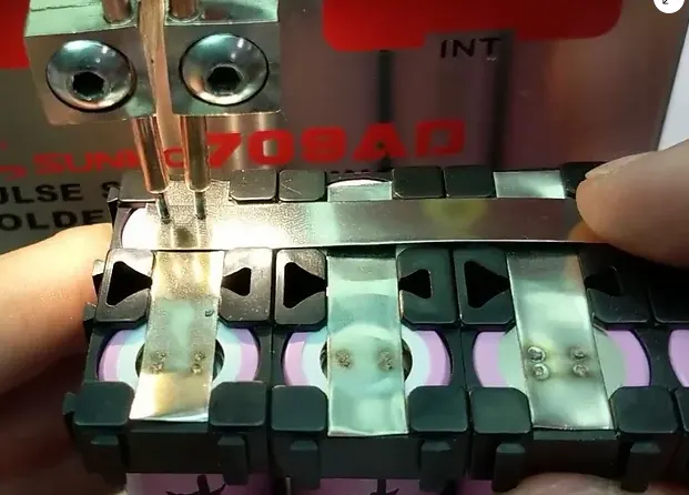
9)Next add the nickel busbar strips that join the cells in series. Use the same approach of 1 weld per cell, wait a minute, and come back to make a second weld. If necessary, add a secondary nickel strip to the serial connection in order to boost up the current carrying capability.
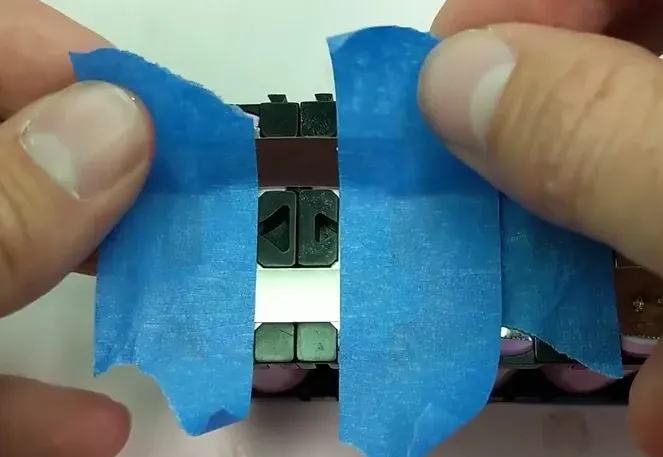
10)Lay down nickel strips on the last parallel cell group on the battery (This needs to be done for both the plus and minus output ends). Using painters tape, lift off the busbar.
11)Spot weld on this end battery connection.
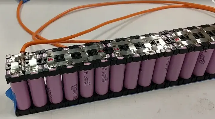
12)Check the battery voltage from end to end at this point to make sure it's what was expected. If it's not the correct voltage, work your way through all the connections and make sure nothing was missed.
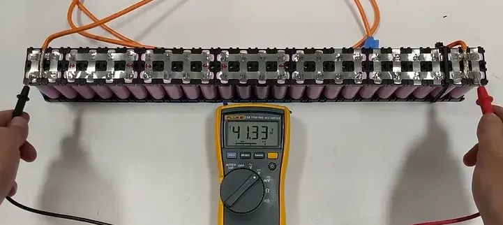
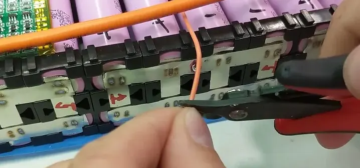
13) Connect all the balance lines of the BMS to the serial connections of the battery
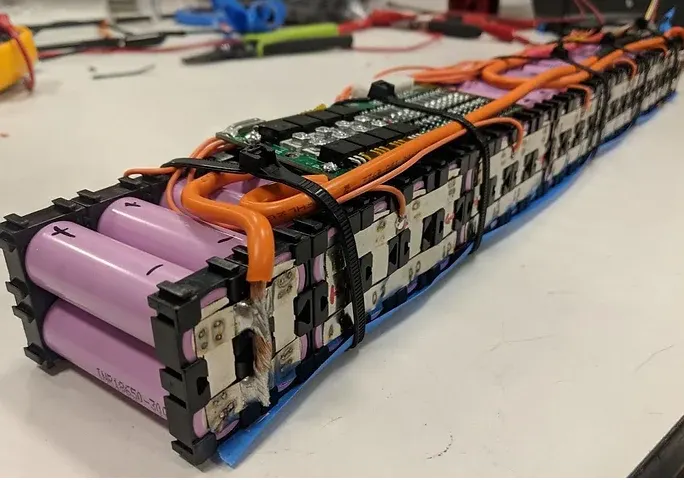
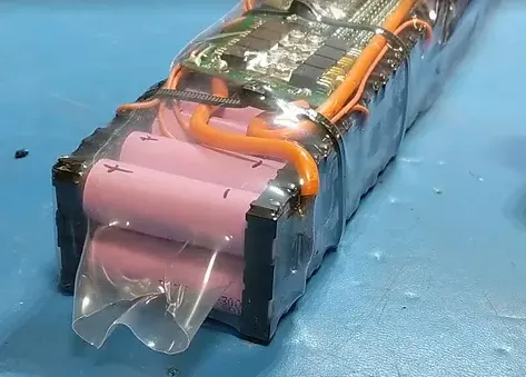
Conclusion:
Lithium Ion and Lithium Ion Polymer batteries are a great power source for some applications but they require preventive protection during discharging and charging.