Project 1 Mechanical design of battery pack
AIM:
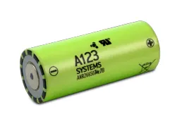
The objective of the project is to create a 18 kWh battery using ANR26650M1-B cells & prepare a detailed battery pack drawing along with its enclosure.
Battery pack
what is cell ?
A cell refers to a single anode and cathode separated by electrolyte used to produce a voltage and current. A battery can be made up of one or more cells. A single AA battery, for example, is one cell.
what is Battery ?
Batteries are a collection of one or more cells whose chemical reactions create a flow of electrons in a circuit. All batteries are made up of three basic components: an anode (the '-' side), a cathode (the '+' side), and some kind of electrolyte (a substance that chemically reacts with the anode and cathode).
when the anode and cathode of a battery is connected to a circuit, a chemical reaction takes place between the anode and the electrolyte. This reaction causes electrons to flow through the circuit and back into the cathode where another chemical reaction takes place. When the material in the cathode or anode is consumed or no longer able to be used in the reaction, the battery is unable to produce electricity.
Battery pack:
It is a set of any number of identical batteries or individual battery cells. They may be configured in a series, parallel or a mixture of both to deliver the desired voltage, capacity, or power density. Components of battery packs include the individual batteries or cells, and the interconnects which provide electrical conductivity between them. Rechargeable battery packs often contain a temperature sensor, which the battery charger uses to detect the end of charging. Interconnects are also found in batteries as they are the part which connects each cell, though batteries are most often only arranged in series strings.
When a pack contains groups of cells in parallel there are differing wiring configurations which take into consideration the electrical balance of the circuit. Battery regulators are sometimes used to keep the voltage of each individual cell below its maximum value during charging so as to allow the weaker batteries to become fully charged, bringing the whole pack back into balance. Active balancing can also be performed by battery balance devices which can shuttle energy from strong cells to weaker ones in real time for better balance. A well-balanced pack lasts longer and delivers better performance.
Case 1: Ladder, linear, F type, or radial

Note that the straps will both come off the top when there are an even number of cells, and one off the top, the other off the bottom when there is an odd number of cells. With a connector and heat shrink wrap they look like this:
The size of a ladder pack is D x nD x H where D is the diameter of the cell, n is the number of cells, and H is the height of the cells.
Case 2: Multi-row cells
There are two ways to start packing them. One could be called the cubic, and the other face centered cubic, or nested.
Cubic packing is in neat rows. The size of such a pack is nD x mD x H, where n is the number of cells in a row, m is the number of rows, D is the cell diameter, and H is the cell height.
Case 3: Face centered "cubic"

Face centered cubic packing is nested to take up less room. Calculating the size takes a little geometry, which follows: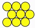
The size is L x W x H where
L = (n +½)D
W = [0.866(p-1)+1] D
H=H
p is the number of rows wide.
Case 4: FCC with alternating long and short rows
If there are alternating long and short rows, such as the 3,4,3 ten cell pack, the formulas are
L = mD
W = [0.866(p-1)+1] D
H = H
Where m is the number of cells in the longest layer, and p is the number of layers. With heat shrink it looks like this:

Case 5: Fixed channel width optimization
What if you have a fixed width channel and want to stagger the cells to maximize the number of cells per unit width? Pull out your high school geometry book, this is trickier!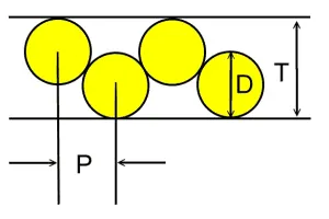
The distance P between the cells of Diameter D in a channel with height T is P = sqrt (2TD-T^2)
So if you have 18mm diameter batteries fitting into a 25.4mm channel, the distance between the cells is 16.8mm. In this case you can fit in an extra cell for every 15 cells, or save 1.2 mm of width per cell.
Battery specification and calculation:
According to the objective we should calculate the capacity 18kwh.
The cell ANR26650M1-B Data sheet :
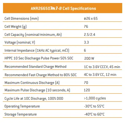
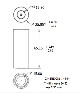
Calculation:
We have,
Cell nominal voltage = 3.3V
Cell nominal capacity =2.5 Ah
, the cell energy capacity is the product of these two parameters = 3.3V × 2.5Ah = 8.25 watt-hr.
The required battery energy capacity is 18 KWh.
Lets take module of 3s & 5p
i.e The voltage of each module will be
=> 3S × 3.3V = 9.9V
& The capacity of each module will be
=> 5P × 2.5Ah= 12.5Ah
Thus we have single module of 9.9V & 12.5Ah Capacity.
Let us assume 48V battery pack.
To make this voltage battery pack we need no. of module in series ,
NSM = 48V/9.9V = 4.8 =5 module (series)
i.e 5 module in series connection required to get 48V battery system.
To get a pack energy of the battery = 18000 wh,
=> 18000 Wh/ 48V = 375 Ah
Which can be get by connecting module in parallel,
To make this pack energy capacity battery we need no. of module in parallel ,
NPM = 375 Ah/ 12.5Ah = 30 module (parallel)
i.e 30 module in parallel connection required to get 375Ah battery system.
Thus we required 5S(module) & 30P(module) while each module has 3S & 5P no. of cell.
i.e Total capacity we get as,
= 5SM × 30PM × (3S × 3.3V) × (5P × 2.5Ah)
= 18,562.5 Wh 18KWh (Battery pack)
The additional energy can be used to compensate for the losses in the battery due to external environmental conditions. The margin can be designed according to the type of application, and in a controlled environment, this margin remains small.
Conclusion:
The battery pack has a voltage of 48 volts and 18kwh , which bring us to a design of 15s 150p battery made by using 8s4p modular configuration where 5 of them are arrranged in series and 30 such arranegemnts are connected in parallel.And total no. of cells used =2250 cells.