Project 1 Mechanical design of battery pack
DESIGN OF BATTERY PACK FOR ELECTRIC VEHICLE
Battery pack capacity: 18 kWh
Cell: ANR26650M1-B
Prepare a detailed battery pack drawing along with its enclosure. State your assumptions.
- Battery.What is it?
ans) An electric battery is a source of electric power consisting of one or more electrochemical cells with external connections for powering electrical devices.All batteries are made up of three basic components: an anode (the '-' side), a cathode (the '+' side), and some kind of electrolyte (a substance that chemically reacts with the anode and cathode).
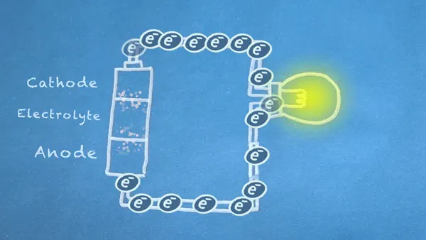
When the anode and cathode of a battery is connected to a circuit, a chemical reaction takes place between the anode and the electrolyte. This reaction causes electrons to flow through the circuit and back into the cathode where another chemical reaction takes place. When the material in the cathode or anode is consumed or no longer able to be used in the reaction, the battery is unable to produce electricity.
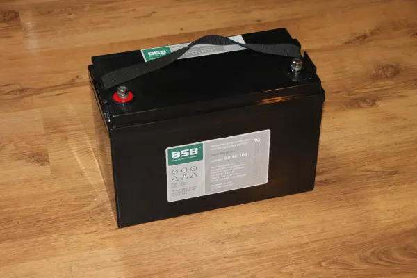
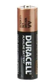
Batteries that must be thrown away after use are known as primary batteries. Batteries that can be recharged are called secondary batteries.Primary cells contain chemistry that cannot be reversed. As a result, the battery must be thrown away after it is dead.Secondary cells can be recharged and have their chemistry reverted back to their original state. Otherwise known as "rechargeable batteries," these cells can be used many times.
OBJECTIVE
- To come up with cell level infrastructure of a high voltage battery pack with 18KW-h energy capacity
- To download the data sheet of Cell: ANR26650M1-B and understand the specifications of it and us it to build the battery pack
- Give a brief view on the enclosure material and facility for the designed battery pack.
THEORY
- The nominal voltage of a battery is the voltage stated by the manufacturer.
- A battery's capacity is a measure of the amount of electric charge it can deliver at a specific voltage. Most batteries are rated in amp hours (Ah) or milliamp hours (mAh).
-
C-RATE---Many batteries, especially powerful lithium-ion batteries, express discharge current as "C-Rate" in order to more clearly define battery attributes. C-Rate is the rate of discharge relative to the battery's maximum capacity.
1C is the amount of current required to discharge the battery in 1 hour. For example, a 400 mAh battery supplying 1C of current would be supplying 400 mA. 5C for the same battery would be 2 A.
BATTERY PACK ARCHITECTURE
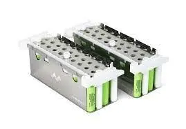
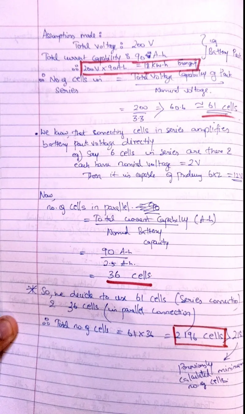
This refers to the arrangement of cells in a battery pack.The way htey are stacked ,their pairings,lineup connections between one another etc. We need to know that connecting cells in series Increase the voltage of the pack and connecting cells in paralell increases battery pack capacity .
Also there are different levels in the pack itself.When we tal about a singular cell and its attributes we say we are dealing with it at a cellular level.A collection of cells connected in series and parralell or both make up a module. Mnay such modules eg)15 or 16 of those make up the final battery pack.So the order of succession goes as:
Cellular level<<< Module Level<<< Battery pack.
 <<
<< <<
<<
Series
In order to increase the voltage between a battery's terminals, you can place the cells in series. Series means stacking the cells end-to-end, connecting the anode of one to the cathode of the next.
By connecting batteries in series, you increase the total voltage. Add the voltage of all the cells to determine the operating voltage. The capacity stays the same.
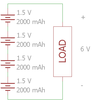
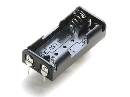
In most consumer electronics that use alkaline batteries, the batteries are stacked in series. For example, this 2x AA battery holder can raise the nominal voltage to 3 V for a project.
Parallel
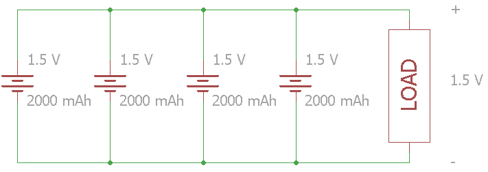
If the voltage of a single cell is adequate for the load, you can add batteries in parallel to increase the capacity. Note that this also means increasing the available current (C-Rate).
Be careful when connecting batteries in parallel! All the cells should have the same nominal voltage and same charge level. If there are any voltage differences, a short circuit could occur causing overheating and possibly fire.
Series and Parallel
If you want to increase voltage and capacity, you can combine series and parallel batteries. Once again, make sure that the voltage level is the same for the batteries in parallel, as a short circuit can occur.
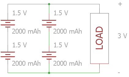
In large battery packs, especially lithium-ion, you often see the configuration listed using 'S' and 'P' for series and parallel. The configuration for the circuit above is 2S2P. As a practical example, modern electric cars use massive arrays of batteries connected in series and parallel.
Battery Holding Systems
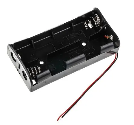
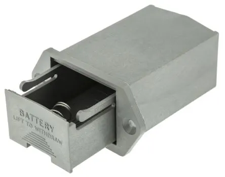
A battery holder is most commonly sold as an integral or removable compartment or cavity, designed to be inserted into - or attached onto - a suitable item of cell-powered equipment.
The primary function of a battery holder is to keep cells fixed in place safely and securely while conveying power from the batteries to the device in question. External connections on battery holders are most often made by contacts either with pins, surface mount feet, soldered lugs or via a set of wire leads.
Battery holders are often designed to be incorporated within the body of an electrical item, but they’re also frequently sold as external compartments or attachments.
Battery holder mounts
Battery holder mounts usually refer to the way the battery holder itself is slotted, secured or attached onto or into the main body of the item being powered. Note, however, that the term ‘battery mount’ is also used to refer to the method by which individual cells are held in place within the overall holder unit.
Battery holder mounts and battery mounts are usually present as an integral part of a complete holder unit, but you can also buy battery mounts cheaply as swap-out or replacement parts. They can come in many different configurations and designs.

Lithium Ion Cell-Battery pack configuration
Cell Level
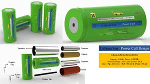
Module Level
Battery Pack level
Battery pack Protection and Venting Systems
The lightweighting of electric vehicle (EV) structures is a key element in helping to extend the endurance ranges necessary to accelerate their increasing adoption. A specific target for weight reduction is the compartment used to house the batteries.The requirement to both support the weight of the batteries and protect them has so far tended to make these enclosures heavy elements in their own right. Now, though, several research initiatives are looking to mitigate that situation through the use of new lighter weight material applications.
An efficient battery housing has many attributes that aid passenger and battery safety, assist in thermal management, while protecting the battery from the harsh environment under the vehicle and in an accident. The system must be produced within the financial and weight constraints of the vehicle.
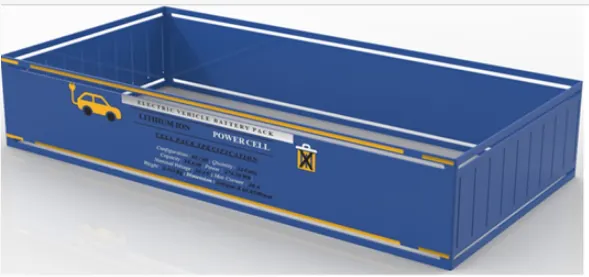
The battery box consists of four primary structural pieces: top cover, bottom cover, internal structure, and side impact crash protection structure. In the image below, the primary load-bearing structural components are identified as the crash structure and the battery frame:
Batteries for electric vehicles (EVs) need protection from harsh external conditions. Generally located on the underside of the vehicle, EV battery enclosures protect the cells from exposure to water, dust, debris and other elements. Like other enclosures, EV battery enclosures also undergo temperature and pressure changes that can lead to problems without proper venting. But EV batteries present unique venting challenges, including potentially dangerous thermal runaway conditions. Considering these challenges, integration of design, manufacturing, installation and testing are crucial to optimal EV battery venting performance.
Numerous components in an EV require venting. Lighting, horns, electronics, powertrain and other components all experience temperature changes resulting from weather conditions, moisture, or heat from electronic circuits.Expanded polytetrafluoroethylene (ePTFE) membranes have proven effective in venting EV enclosures and providing pressure equalization. This material allows gases to flow in and out of the enclosure but helps prevent liquid and particle contaminants from entering the enclosure.
The size of EV battery packs also presents challenges. Weighing up to 2,000 lb. (about 900 kg), the packs contain hundreds – sometimes thousands – of cells, with large air volumes that can exert forces on the enclosures as pressures increase. This creates significant venting needs to account for differential pressure due to altitude or temperature change.
Perhaps the biggest challenge with EV battery packs is the potential for thermal runaway. If lithium-ion battery cells are damaged by puncturing, overcharging, manufacturing defect or other causes, they can release gas and heat. This can trigger other cells to decompose, leading to a thermal runaway condition, where rapidly increasing temperatures and pressures released by cells exceed the venting capability of the ePTFE membrane vent.
Wiring Between Cells in a battery pack
We can use a variety of conducting wires or metallic strips to connect cell terminals for series and parallel connections.Most commonly used one is Nickel Strips.Nickel strip is generally used in battery building. Its due to its efficiency of usage in spot welding and soldering as well its high corrosion resistance over time. It has good properties and excellent resistance to many corrosive environments. The pure nickel will never get rust after it applied to battery packs. It won’t affect the current transfer between batteries.
Pure nickel strips are the material you want, but many vendors swap out it for nickel-plated steel strips, which are poorer and have greater resistance – not suitable for most battery projects.

Battery Management System
A battery management system is any electronic system that manages a rechargeable battery, such as by protecting the battery from operating outside its safe operating area, monitoring its state, calculating secondary data, reporting that data, controlling its environment, authenticating it and / or balancing it.
A BMS may monitor the state of the battery as represented by various items, such as:
- Voltage: total voltage, voltages of individual cells, or voltage of periodic taps
- Temperature: average temperature, coolant intake temperature, coolant output temperature, or temperatures of individual cells
- Coolant flow: for liquid cooled batteries
- current in or out of the battery
- Health of individual cells
- SOC of cells
A BMS may protect its battery by preventing it from operating outside its safety regions, such as:
- Over-current during charging
- Over-current during discharge
- Over-voltage during charging, especially important for lead acid and Li-Ion cells
- Under-voltage during discharging
- Over-temperature
- Charging while under temperature
- Over-pressure

Calculations for the Design of 18KW-h battery pack
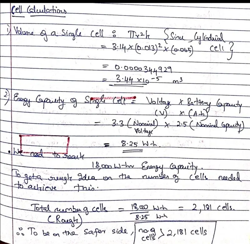
The cell used here is an ANR26650M1-B .The details about said cell are as follows:
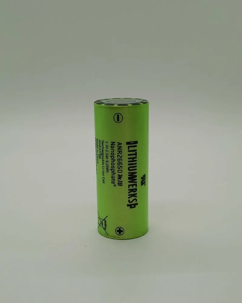
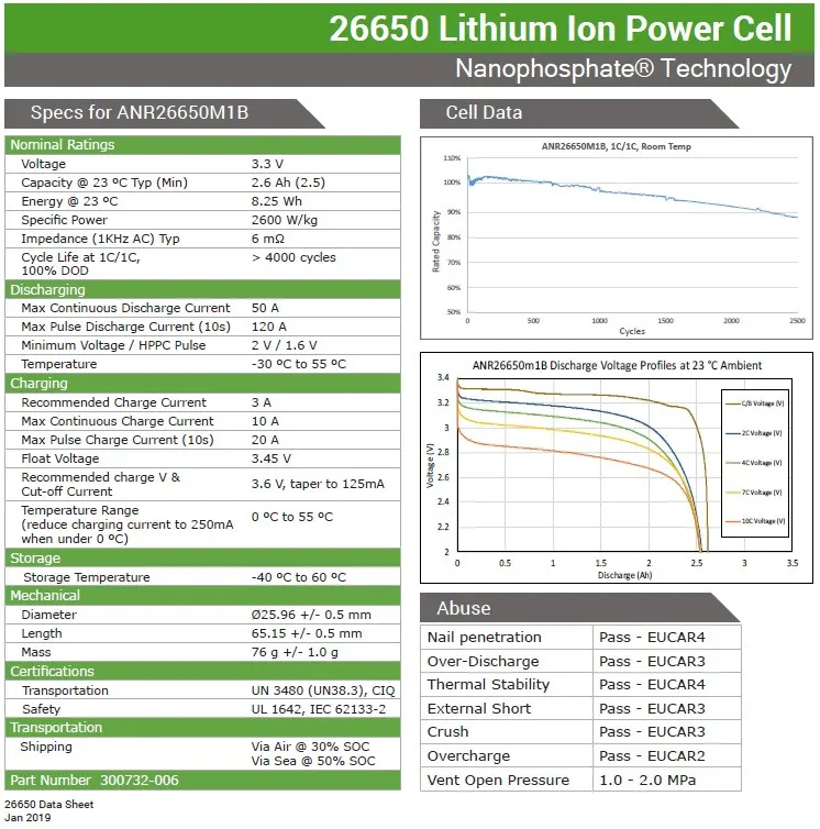
ANR26650M1-B Specifications
Nominal Ratings
Voltage: 3.3 Volts
Capacity: 2.5 Ah
Energy: 8.25 Wh
Specific Power: 2600 W/kg
Impedance (1KHz AC Typical) 6 mΩ
Cycle Life at 1C/1C, 100% DOD: > 4000 cycles
Cell Type: 26650 Lithium Ion Power Cylindrical Cell
Discharging
Max Continuous Discharage: 50 A
Max Pulse Discharge Current >50% SOC (10s): 120 A
Minimum Voltage: 2 Volts
Temperature: -30ºC to 55ºC
Charging
Recommended Standard Charge: 2.5 Amps
Max Charge Rate: 10 Amps
Max Pulse Charge Current <50% SOC (10s): 25 A
Float Voltage: 3.45 Volts
Recommended charge V & Cut-off Current: 3.6 Volts, taper to 125mA
The calculations for my battery pack design are as shown in the following Images:
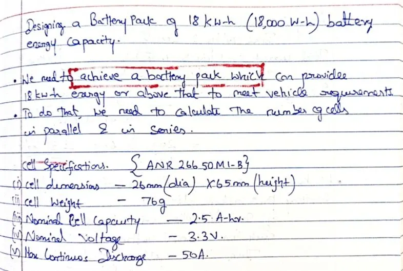
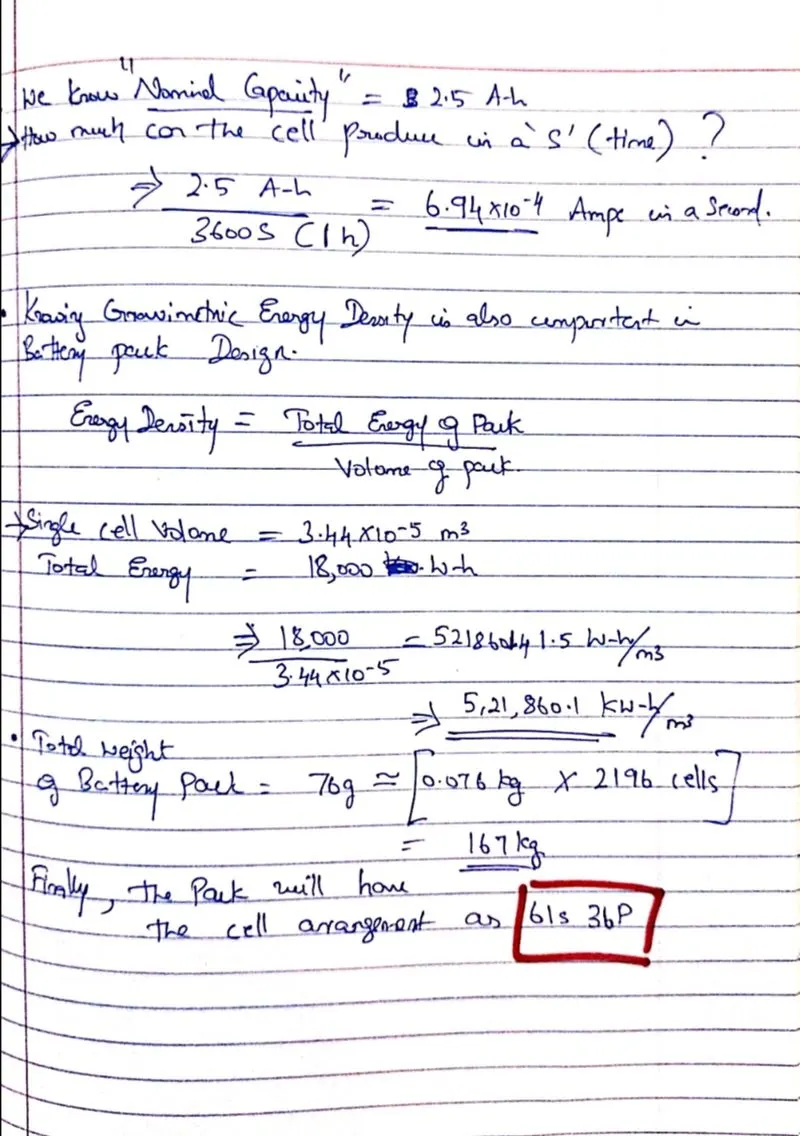
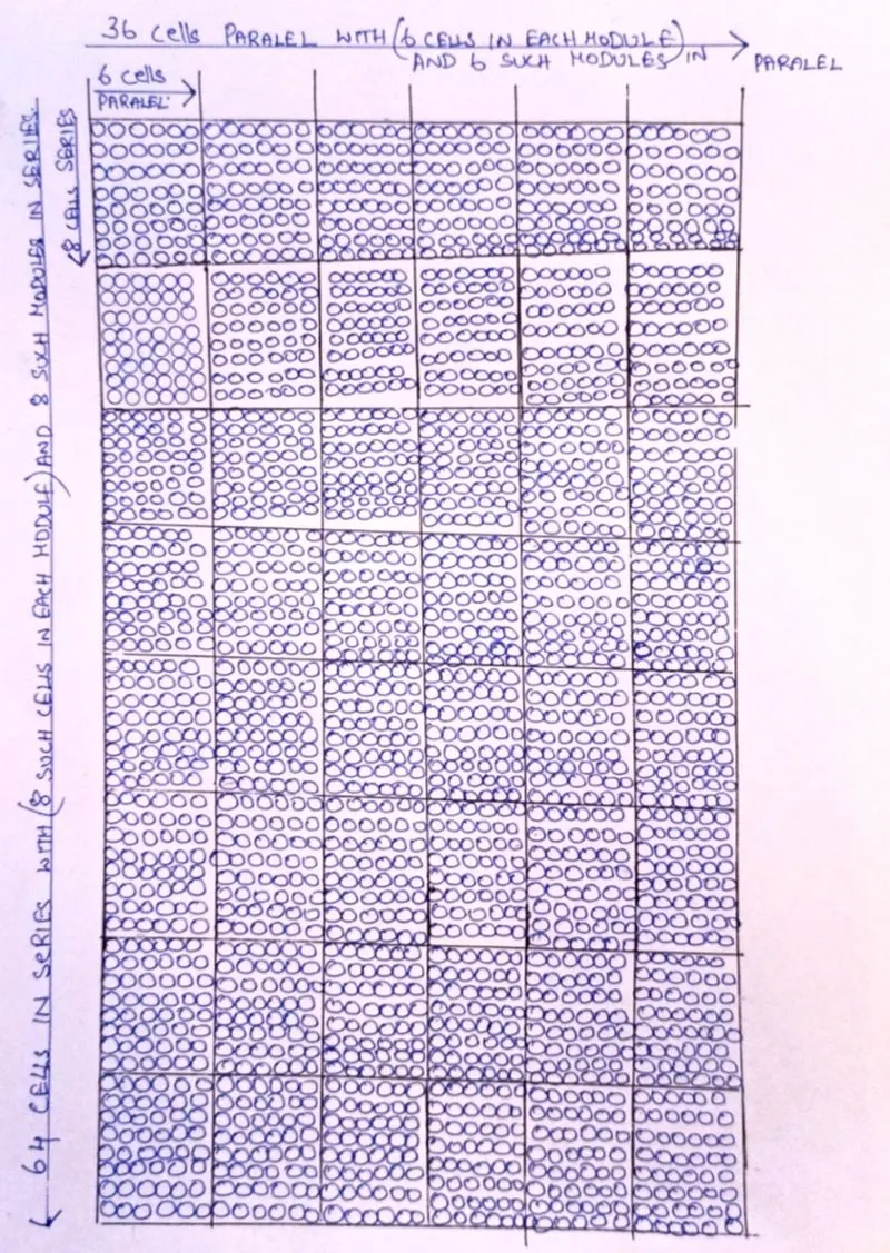
Now to show the design of the module for such a battery configuration: ( For convinience i have designed a 64s36p pack for 61s is an odd number of series cells)
Module Level

Battery Pack Look