Project 1 Mechanical design of battery pack
The battery pack to be constructed is of 18 KWh. This kind of pack is generally used in small range electric car. We can take the example of Tata Tigor EV to make assumptions, since it has battery pack 21.5 KWh, which is nearly the same specification. Tata Tigor EV is driven by 3 phase 72 V induction motor. Thus, we can make an industry relevant battery pack of 72 V with capacity of 18 KWh. In order to calculate number of cells required, first we need to know specifications of the cell : ANR26650M1-B. It's manufactured by A123 systems and is LiFePO4 type cell chemistry. It's specifications is given below -
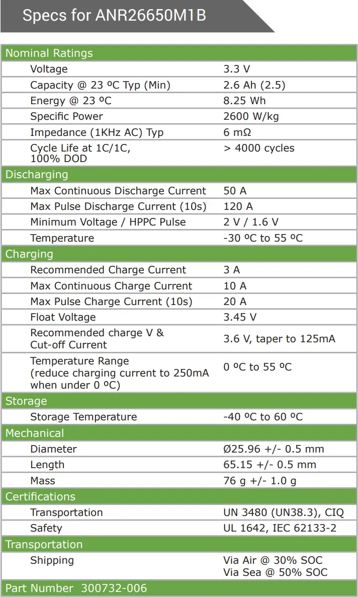
According to specifications, the nominal voltage of cell = 3.3 V. We need net output voltage of minimum 72V to drive the induction motor. Thus, we will put cells in series.
No. of cells in series = Motor Voltage Rating / Cell Nominal Voltage = 72/3.3 = 21.8 ≈ 22 Cells in Series
Now, since we have calculated cells in series, we can use this to calculate number of cells in parallel. According to specifications, energy rating of each cell is = 8.25 Wh and we need total energy of 18000 Wh. Then,
Total no. of cells = no. of cells in series x no. of cells in parallel
Energy of each cell x Total no. of cells = Total Pack Energy
8.25 x 22 x no. of cells in parallel = 18000
no. of cells in parallel = 18000/(8.25x22) = 99.17 ≈ 100 cells in parallel
Now, we know that we need 22 cells in series and 100 cells in parallel to make the suitable battery pack. Thus, we will look into it's arrangement. Generally, electric cars prefer battery pack at flooring to reduce CG of the vehicle and improve it's handling. Thus, we will keep it single celled in height. Now, in order to have almost equivalent sides, we can put each parallel connected module of 100 cells in two rows of 50 cells each. Then, each parallel connected module will be connected to 21 more such modules in series. Thus we will have one side with 50 cells and other side with 22 x 2 = 44 cells. This schematic is shown in image below -
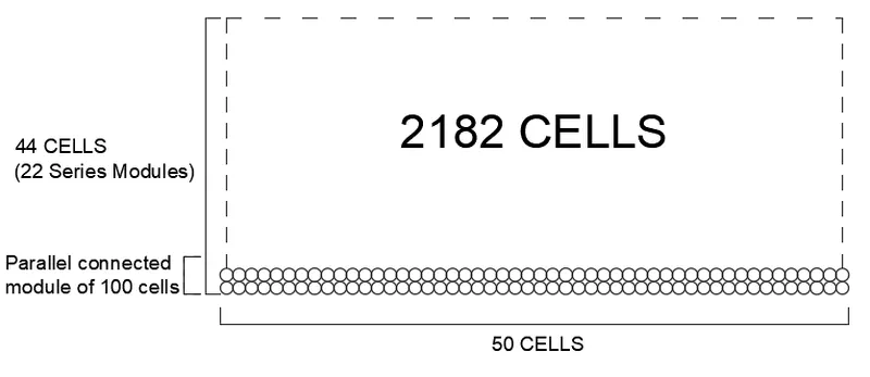
ASSEMBLY PACK SCHEMATIC DIAGRAM
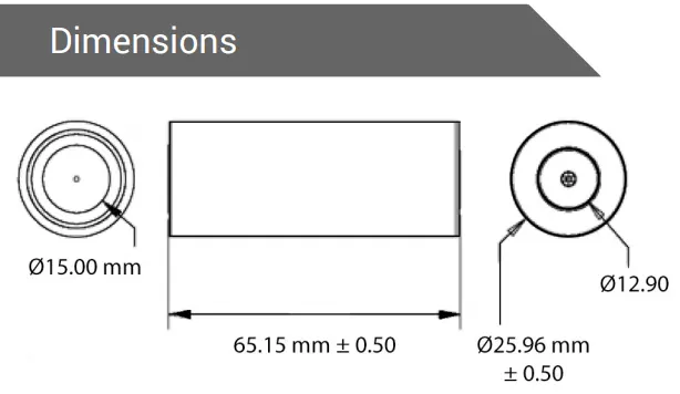
To construct pack assembly, first parts are constructed. Firstly, cell is constructed in CAD. Solidworks is used as CAD software for it's great rendering capabilities. The cell is constructed according to the mechanical dimensions given in the datasheet as shown below -
From these dimensions, cell is rendered as shown below with top view and bottom view-
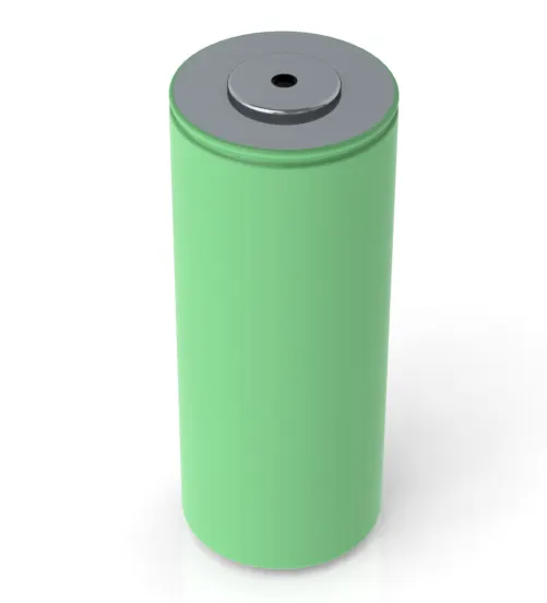
TOP VIEW RENDERING

BOTTOM VIEW RENDERING
After that, cell holder is modelled. The rendering material is used plastic and dimensions are according to available holders in the market. It's rendered model is shown below -
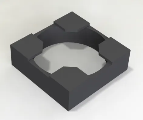
CELL HOLDER RENDERING
After, that nickel strips are modelled. Long nickel strip for whole array of 50 cells and short nickel strip for cell to cell connection. The renderings of both the models is shown below.

SMALL STRIP RENDER

LONG STRIP RENDER
Finally, assembly is made from individual parts. For the assembly, each parallel connected module is connected with nickel strips and for series connection positive of one module is connected to negative of other. Thus, subsequent parallel connected modules are kept in reverse order. The final rendering of overall pack is shown below -
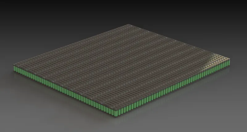
FINAL ASSEMBLY PACK RENDER