Mechanical design of battery pack
Mechanical design of battery pack
Aim - In this project we are going to design a li-ion battery pack with a maximum capacity of 18kWh
Theory - A battery pack is a collection of many cells arranged in series and parallel combinations which increase the energy and power density. In this project, we are designing a battery pack using an LFP cell array.
Types of Assembly -
Theory - There are major 2 types of combination which are used in assembling the batteries these are,
- Series
- Parallel
let's understand each one of them in detail,
1. Series Combination - When the positive terminal of one cell is connected to the negative terminal of the following cell in a battery, the cells are referred to as series-connected or simply series batteries. The battery's overall emf is the algebraic sum of all individual cells connected in series in this case. However, the battery's aggregate discharged current does not surpass the discharged current of individual cells.

2. Parallel Combination - In a battery, the cells are said to be connected in parallel when the positive terminals of all cells are connected together and the negative terminals of these cells are also connected together. Parallel batteries are another name for these combinations. If each cell's emf is the same, the emf of the battery multiplied by n cells linked in parallel equals the emf of each cell.
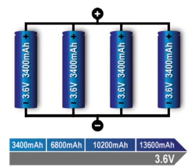
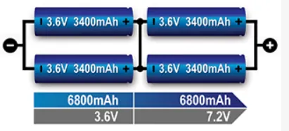
Apart from these 2 major combination types, a battery pack uses them together to create variation in current and voltage values. Also known as mixed variation in battery cells,
3. Series-parallel Combination - A battery's cells can also be connected in a series-parallel configuration. This type of battery is sometimes referred to as a series-parallel battery. A load may require more voltage and current than a single battery cell can provide. The desired number of battery cells can be connected in series to achieve the requisite load voltage, and the desired number of these series combinations can be connected in parallel to achieve the required load current.
About LFP battery -
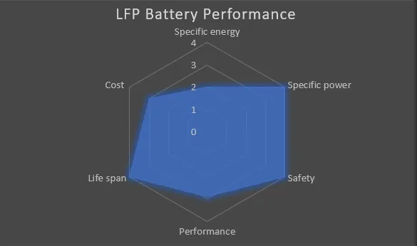
Because of its technical benefits and an extremely high degree of safety, lithium Ferro phosphate technology (also known as LFP or LiFePO4), which first appeared in 1996, is rapidly displacing previous battery technologies.
This technology is employed in medium-power traction applications (robotics, AGV, E-mobility, last-mile deliveries, etc.) or heavy-duty traction applications due to its high power density (marine traction, industrial vehicles, etc.)
Because of the LFP's extended service life and the ability to deep cycle, LiFePO4 can be used in energy storage applications (stand-alone applications, Off-Grid systems, self-consumption with batteries) or stationary storage in general.
Advantages -
- Very safe and secure technology (No Thermal Runaway)
- Very low toxicity for the environment (use of iron, graphite, and phosphate)
- Cycle life: Around 2000 Cycles depending on the usage
- Operational temperature range: up to 70°C
- Very low internal resistance. Stability or even decline over the cycles.
- Constant power throughout the discharge range
- Ease of recycling
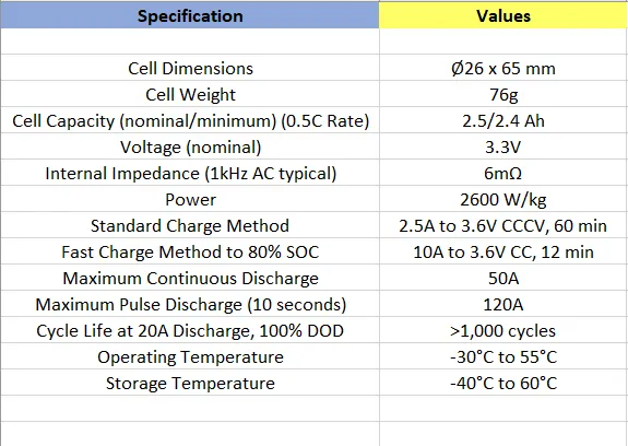
Cell Code - ANR26650M1-B
Data Sheet -
Data Sheet PDF - https://www.batteryspace.com/prod-specs/6610.pdf
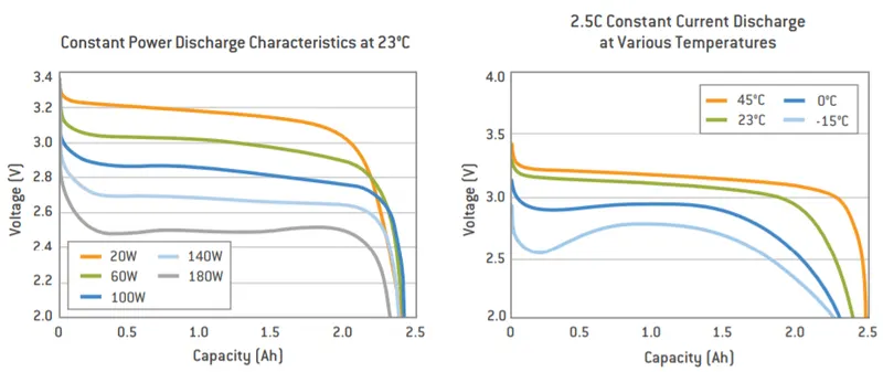
Assumptions -
- The Voltage of the battery pack is assumed to be 330 V.
- Distance between 2 cells is assumed to be 5mm
- The pack is divided into 2 modules
Calculation -
- Energy `= V*I`
`18kWh=330*I`
`I=(18 000)/330=54.54Ah`
- Number of Cell in Series,
Cell Voltage - 3.3V
Number of cells - Pack Voltage/Cell Voltage = 330/3.3V - 100 Cells(approx.)
- Number of Cell in parallel,
Cell capacity - 2.5Ah
Number of cells - Pack current/Cell current - 54.54/2.5 - 22 Cell(approx.)
- The Assembly Configuration - 100S22P
From the above calculation, we can see that we need 100 cells in series and 22 in parallel,
Total number of cells in the pack - 100*22 = 2200 cells,
- Weight of Battery pack
Weight of pack - No. of cells * weight of each cell - 2200*72g - 158.5kg
- Length of the Battery pack
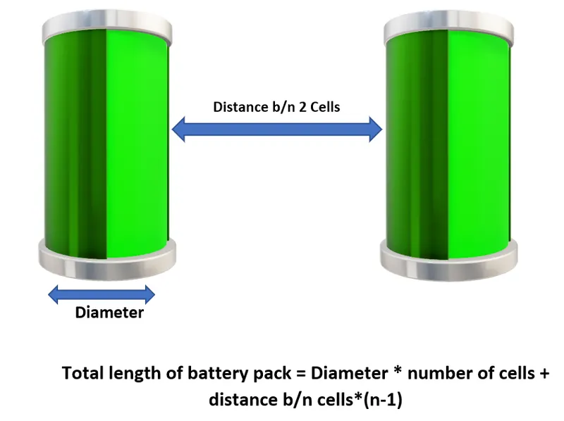
Length of battery pack - (26*100)+(5*99) = 3095 mm
Width of battery pack - (26*22)+(5*21) = 677 m
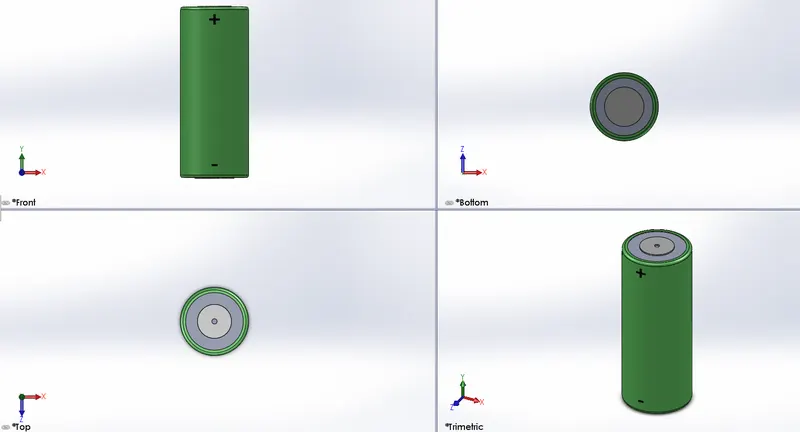
Drawing of Cell -
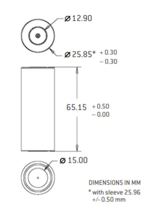
CAD model -
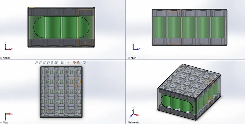
The CAD model with the current configuration is not feasible for practical use. but for reference purposes, I have created a smaller configuration model using Solidworks.
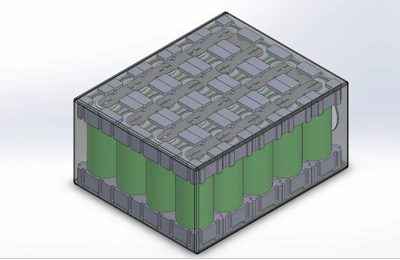
Lithium Cell -
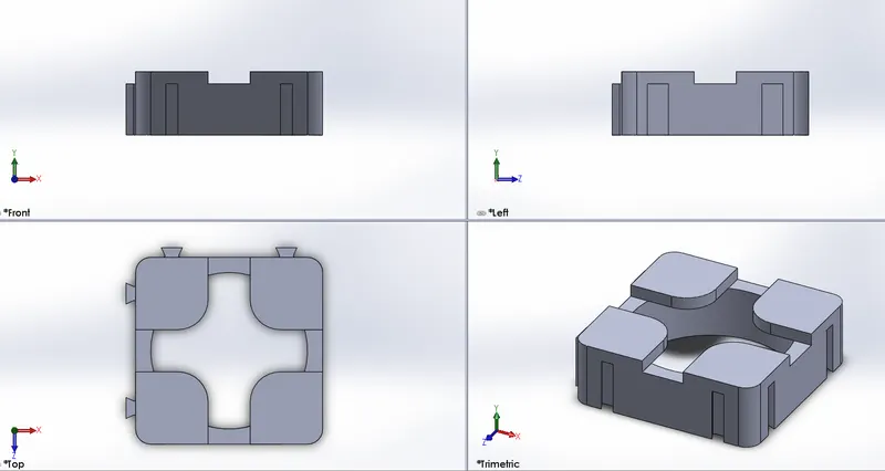
Cell Holder -
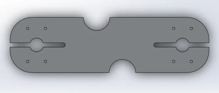
Connector Strip -
#Cell holders are used to align and hold the lithium cells in positions before spot welding
# Nickle tape is spot welded on the battery terminals to provide the required connections
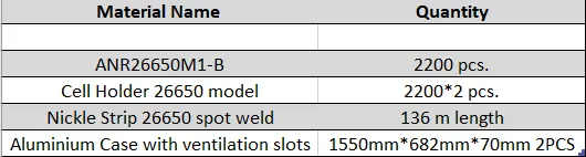
Bill of Material -
Limitations -
- In order to fulfill the required power and current output, 100 cells in series and 22 cells in parallel are required which significantly increase the weight of the pack.
- A large number of cells generate a huge amount of heat which is not suitable and may result in a thermal runaway of the battery pack.
- To overcome the above problem the pack can be further divided into smaller modules which can be managed more efficiently.
- Without a BMS it is not possible to use the battery pack within the safety limits.
Future Scope -
- The battery pack can be divided into smaller modules which can reduce the need for a hi-tech thermal management system for the pack.
- Different chemistry types of cells can also reduce the size of the battery pack without changing the current and voltage values.
- A battery management system can optimize and increase the life of the battery pack by proper cell balancing algorithms.