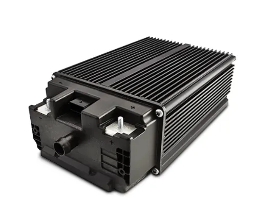
Project 1 Mechanical design of battery pack
Aim:- Mechanical design of battery pack
Object:-
Battery pack capacity: 18 kWh
Cell: ANR26650M1-B
Prepare a detailed battery pack drawing along with its enclosure. State your assumptions.
Introduction:- An electric battery is defined as a device that makes use of either one or an assembly of electrochemical cells that convert the stored chemical energy within them into electrical energy. Each cell has a positive terminal, cathode, and a negative terminal, anode. The individual cells are connected in various combinations of series and parallel connection to get a battery of desirable characteristics.
A battery pack is a set of any number of (preferably) identical batteries or individual battery cells. They may be configured in a series, parallel or a mixture of both to deliver the desired voltage, capacity, or power density. The term battery pack is often used in reference to radio controlled hobby toys and battery electric vehicles. Components of battery packs include the individual batteries or cells, and the interconnects which provide electrical conductivity between them. Rechargeable battery packs often contain a temperature sensor, which the battery charger uses to detect the end of charging. Interconnects are also found in batteries as they are the part which connects each cell, though batteries are most often only arranged in series strings.
An advantage of a battery pack is the ease with which it can be swapped into or out of a device. This allows multiple packs to deliver extended runtimes, freeing up the device for continued use while charging the removed pack separately.
Another advantage is the flexibility of their design and implementation, allowing the use of cheaper high-production cells or batteries to be combined into a pack for nearly any application.
At the end of product life, batteries can be removed and recycled separately, reducing the total volume of hazardous waste.
Some basic terms related to the Battery:-
Voltage:- Total voltage, voltages of individual cells, minimum and maximum cell voltage, or voltage of periodic taps. In order to maximize the battery's capacity and to prevent localized under charging or over charging, the BMS may actively ensure that all the cells that compse the battery are kept at the same voltage or the State of charge, through balancing.
Temperature:- Average temperature, coolant intake temperature, coolant output temperature or temperature of individual cells.
State of Charge(SOC):- Deopth of charge(DOD) to indicate the charge level of the battery.
State of Health(SOH):- A variously defind measurement of the remaining capacity of the battery as % of the original capacity.
State of Power(SOP):- The amount of power available for a defined time interval given the current power usage, temperature and other conditions.
Current:- Current in or out of the battery.
Cell used to make Battery Pack
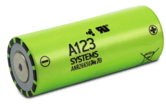
Technical Data for the Cell used in Battery Pack
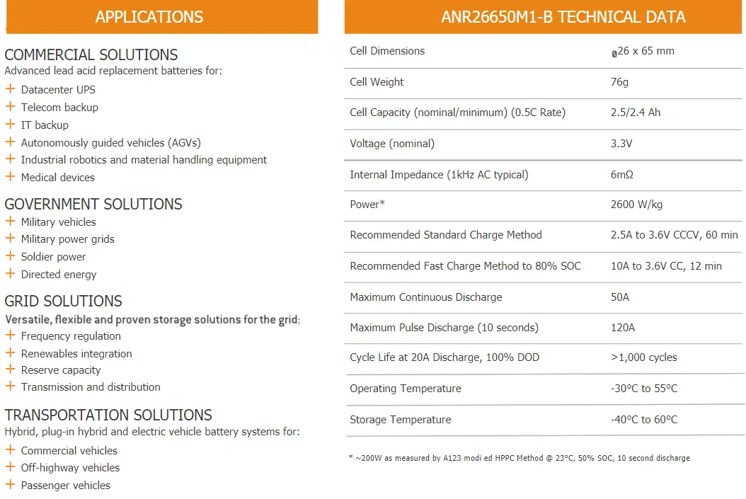
Requirement of battery pack = 18 kwh
Taking ideal factors and environments into mind, i aimed for a capacity of 20kwh (which has the factor of safety inculded)
To get a total of 20kwh energy for the battery pack a cell configuration of 45s56p was used which gives an equivalent nominal voltage of 148.5v and an equivalent capacity of 140Ah which gives total energy of 20.79kwh.
(148.5/3.3 = 45) because in series voltage are added up
for parallel 140/2.5=56
Battery Holder:- It is made of a blend of PC/ABS (Polycarbonate/ Acrylonitrile Butadiene Styrene) providing a combination of the high processability of ABS with the excellent mechanical properties, impact and heat resistance of PC. It is heat resistant and cracks resistance, making it good for holding multiple cells in close proximity where temperature may rise to very high levels due to the heat produced by current. High impact strength even at low temperatures- This allows operation in a wide temperature range.
High Stiffness- allows the battery pack to be compact and solid low overall shrinkage and high dimensional accuracy. They can be 3D printed or made from traditional processes like injection modeling which give high dimensional accuracy and high efficiency of manufacturing with minimum finishing requirements.
The holder was designed keeping in mind that the cells need to be press-fit into the holder so that the cells don't get loose. A minimum distance of 1mm was kept at the boundaries and was gradually increased to 4mm in the middle of the battery pack as in that place the heat generation would be maximum due to surrounding cells in all directions. The larger gaps allow convective current to dissipate heat more effectively and to prevent a dangerous situation where excessive temperature could lead to explosion of the cells.
A subassembly of the holder has been used as linear pattern in the main assembly-Top view of Battery Holder
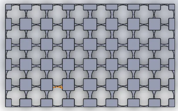
Design of Battery Cell-

Nickel Strips:- Nickel Strips are used for connecting individual cells are called interconnects most cells are nickel coated and thus using nickel strips prevent galvanic corrosion which takes place when one metal corrodes another dissimilar metal when it is in electrical contact with it, in the presence of an electrolyte. They have high tensile strength of 345-1000Mpa, low electric resistivity of 6.99e- 8 ohm and easy and quick soldering by spot welding. Spot welding is a type of electric resistance welding used to weld sheet metals, through a process in which contacting metal surface points are joined by the heat obtained from resistance to electric current.

Adding the BMS:- A battery management system(BMS) is any electronic system that manages a lithium battery pack and the main functionalities are-
1. Monitors all of the parallel groups in the battery pack and disconnect it from the input power source when fully charged.
2. Balance all the cells voltage equally.
3. Doesn't allow the pack from over discharged.
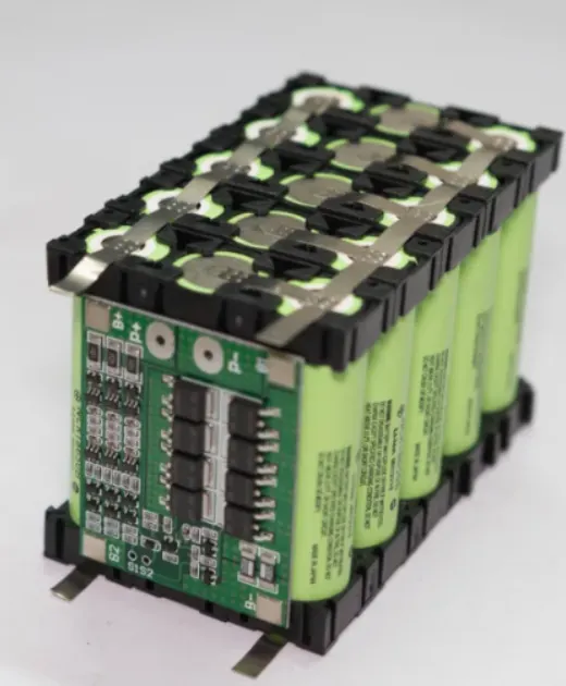
The Battery pack have all around exposed nickel strips, to avoid any accidental shorting an Enclosure used.