Project 1 _Creating an Architectural plan for the provided plot size and develop relevant basic structural drawings
Aim and Introduction:-
To design and draft a residential building with the given plot size and develop both architectural and structural drawings.
Procedure:-
Commands Used-
- Xline
- Line
- Copy
- Move
- Hatch
- Fillet
- Layer Properties
- Block
- Insert
- DIMLINEAR
- DIMCONTINUE
- TEXT
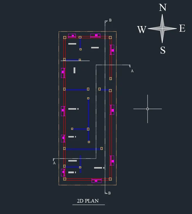
1) Created a new 'dwg' file and set the units and limits through the commands UNITS and LIMITS.
2) Through LINE command created the direction as shown in the figure.

3) Went to Layer Properties and created the necessary layers that is required for drawing to be carried out.
4) Then,created a rectangle with the given plot size with the help of LINE command with the layer Exterior Wall.
5) Created external wall with the help of OFFSET command giving the offset distance as 9".
6) Created the Interior wall with the help of LINE command and OFFSET command by taking the offset the distance as 4.5" by putting the appropiate into consideration.
7) Created the door openings with the help of TRIM command.Kept the door size as 4' for main entrance,3' for bedroom door and 2'6" for restroom door.
8) After that,created the dimensions with the help of DIMLINEAR command.
9) Named each room with the TEXT command.
10) Created a 10'x 10' and 9'x10' column pasted on the necessary areas with the COPY command.
Thus,completing the 2D Plan.
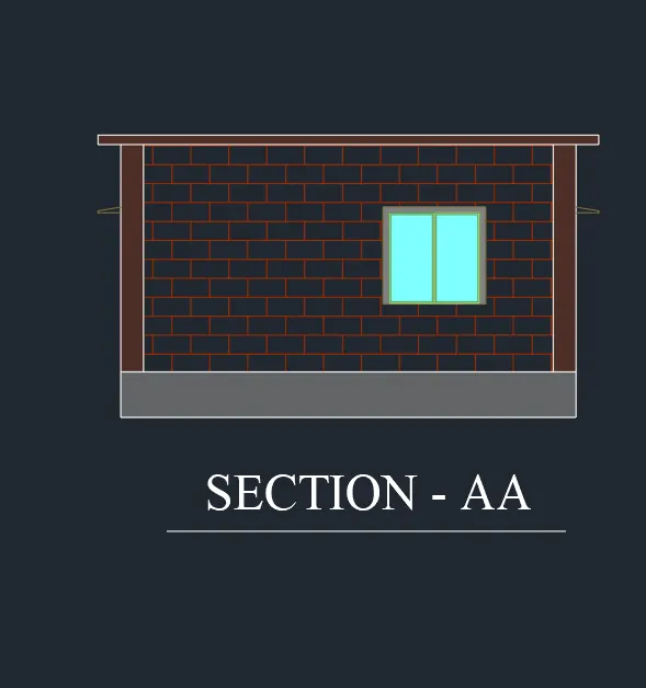
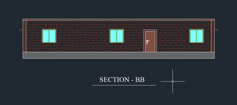
11) For the section AA and section BB, projections were drawn with the help of XLINE command.
12) By OFFSET and LINE command,the section is created.
13) Windows and Doors are created by taking appropiate dimensions into consideration.After that,by HATCH command,hatching is done.
Thus, in this way,both the sections and elevation were created.
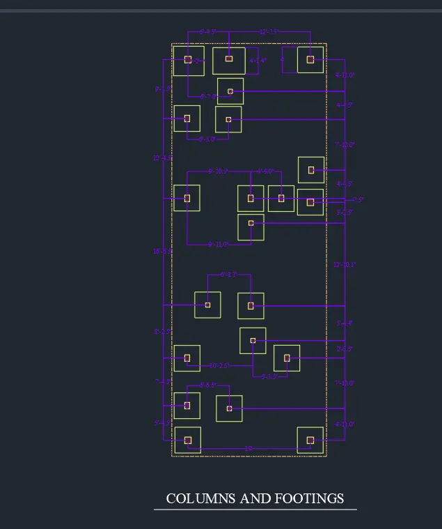
14) For creating the Column and Footing Drawing,off the layers on the 2D plan and then copied the plan to the different location.
15) Giving the footing sizes as 5'x5' and 4'x4' wherever necessary by creating them on a different layer.
16) DIMLINEAR and DIMCONTINUE were used for giving the dimensions.
Thus,with these ways,column and footing drawings were created.
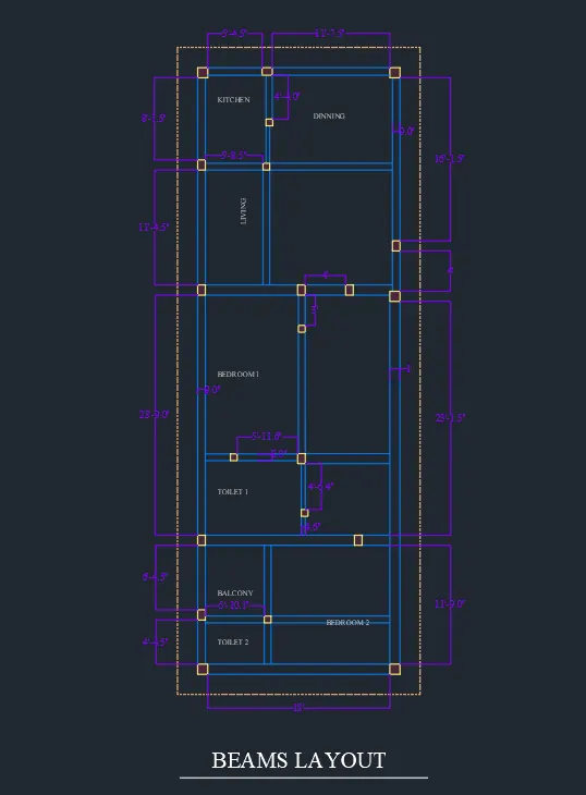
17) For creating the Beam drawing,off the layers and copied the 2D plan to a different location.
18) Created a different layer for beams and with the help of LINE command created the beams wherever necessary.
19) 9'x12',9'x9' and 4.5'x9' beams were created.
20) Dimensioning is done with the help of DIMLINEAR and DIMCONTINUE command.
In these ways,beams drawing is created.