Project 1 _Creating an Architectural plan for the provided plot size and develop relevant basic structural drawings
AIM:
TO DRAFT THE PLAN IN THE PLOT SIZE 60'X20' AND SKETCHING PLAN, ELEVATION, SECTION, LAYOUT OF BEAM, LAYOUT OF COLUMNS, LAYOUT OF FOOTINGS OF THE PLAN.
INTRODUCTION
FOLLOWING TOOLS IN THE AUTO CAD ARE USED TO DRAW THE DRAWINGS:
1. Line: Draw lines in AutoCAD
2. Polygon: Draws polygons with three or more sides
3. Rectangle: Used to draw rectangles
4. Circle: Command used to draw circles
5. Ellipse: Used to draw ellipse.
6. Erase Erase object in the drawing area
7. Copy-Used to copy one or more objects
8. Mirror - Command used to mirror an exact duplicate of an object.
9. Offset- Used to offset one object from another a distance you specify
10. Extend-Used to extend one line to another
11. Array-Use to make a rectangular or polar array of an object
12. Move - Used to move objects around in the drawing area
13. 13.Rotate - Used to rotate an object around a base point
14. Scale - Command used to make an object larger or smaller
15. Trim - Command used to trim an object from another object
16. Chamfer-Used to put a chamfer between two lines
STEPS FOR DRAWING PLAN- (GROUND AND FIRST FLOOR PLAN)
Open auto Cad and enter UN (Units command) in the command box and select type as decimal and setprecision of decimal as O
Select X line command and draw horizontal line and vertical line.
Trim the unwanted line.
Offset 230 as external wall to both horizontal and vertical line.
Trim the corner points.
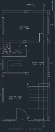
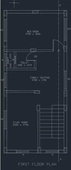
Offset 3100 in X direction and offset 3000 in Y direction for bedroom.
Offset 230 for external wall.
Offset 600 for shaft
Offset 1500 and 1370 for toilet.
Offset 150 for internal wall
Offset 2400 horizontal for kitchen and 1700 in vertical direction for kitchen.
Offset 2550 in horizontal and 4750 in vertical for drawing room.
Offset 1000 for landing o staircase
Offset 300 for tread of staircase
Drawing of doors and windows- Line command is used for drawing of windows and doors.
Sizes of doors and windows are as follows
Doors (DIMENSIONS ARE IN MM)
D-1200 X 2100.
D1- 900 X 2100.
D2- 750 X 2100.
Windows (DIMENSIONS ARE IN MM)
W= 1000 X 1200.
W1-1500 X 1200.
W2-1200 X 1050.
W3= 180 X 1200.
W4-600 X 1050.
Windows are drawn by using line command.
Section lines are drawing by using layer and changing the layer type.
Hatch-For hatching the columns type hatch in command box- open settings -select pattern-select pattern as AIR-CONC-select global scale factor as 0.7.
Dimension- For drawing dimension using dimension tool in the ribbon.
Text- For naming of plan use text in ribbon in that use multiline text and keep the height of text as 220.
GROUND FLOOR PLAN:
FIRST FLOOR PLAN:
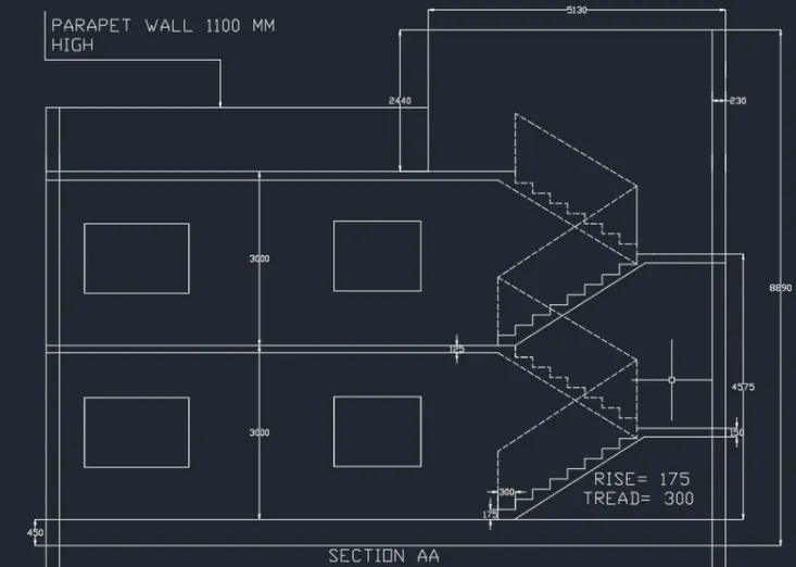
STEPS FOR DRAWING SECTION AA:
Rotate the entre plan drawn earlier in the 90 degrees direction to draw the section
Select x line command and take the projectors of the rotated plan in the downward manner.
Take the projections of all internal walls of 150 mm and eternal walls of 230mm.
Draw a base line to draw the section BB. Offset 450mm from the ground level.
Offset 3000 for ground floor.
Offset 3000 for second floor.
Offset 1100 for parapet wall.
Offset 2450 from terrace level for mumty.
For drawing of staircase offset 300 for tread and offset 175 for rise of staircase.
Draw the chajjas and windows as per the sizes considered and standards.
Draw the railing of staircase in dash manner from the layers and change the layer to ACADISO03W100.
Thickness of slab is 125mm.
Offset 125 below the line of first floor of 3000.
Give the dimensions by dim linear or dim continue command,
Select the multiline text for naming of the section.
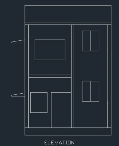
STEPS FOR DRAWING ELEVATION:
Select x line command and extend the lines from the plan in the downward manner to create projections.
Offset 450mm from the ground level for plinth
Offset 3000 for ground floor.
Offset 1100 for parapet wall.
Offset 2450 from terrace level for mumty
Draw the chajjas and windows as per the sizes considered and standards.
Give the dimensions by dim linear or dim continue command.
Select the multiline text for naming of the section.
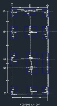
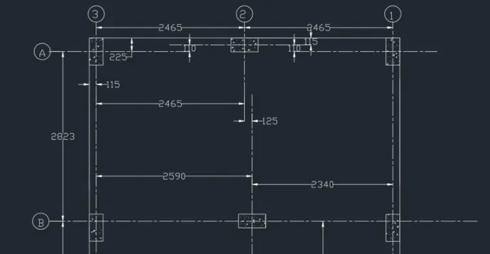
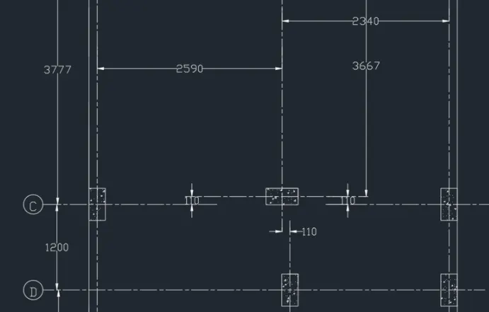
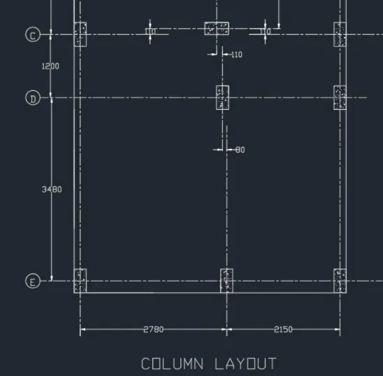
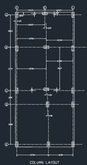
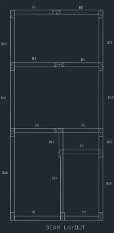
STEPS FOR DRAWING COLUMN LAYOUT, BEAM LAYOUT, FOOTING LAYOUT:
Line command is used for drawing the layouts.
Size f column is assumed as 230 x 450.
Dim linear command is used for dimensions of centreline.
Line type is changed from layer to continuous dash type.
Hatch is used for hatching the columns as AIR CONC type.
COLUMN LAYOUT DRAWING
BEAM LAYOUT DRAWING:
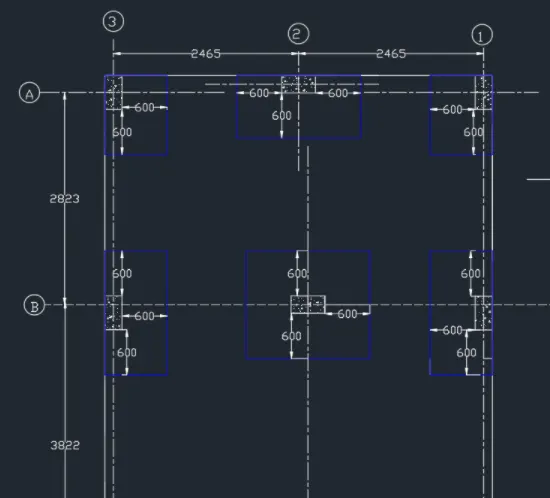
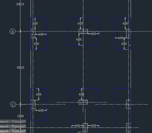
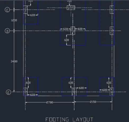
FOOTING LAYOUT: