Project 1 _Creating an Architectural plan for the provided plot size and develop relevant basic structural drawings
ASSIGNMENT NO 8
Q1. Design and draft a layout of residential building with following details.
Plot size = 60’ * 20’ (18.3m * 6m)
Orientation – facing east
Also draw architectural drawing and structural drawing.
Ans -
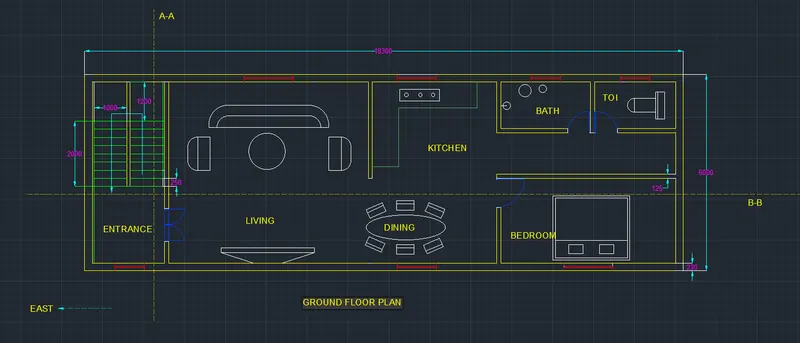
Step 1 - Creation of ground floor plan
First open the auto cad software in the laptop.
The plot size is given as 18.3m * 6m.
Take X line command to draw a horizontal infinite line and also on the Ortho mode for 90 degree
Line.
With x line draw a vertical line too for vertical distances.
Type o for offset command and draw a line parallel to vertical line at a distance of 230mm as we are taking wall thickness of 230 mm.
Type o for offset command and draw a line parallel to 2nd vertical line at a distance of 1000 mm for the length of stairs.
Again type o for offset command and draw a vertical line of 50mm parallel to 3rd line.
Type o for offset command and draw a line parallel to 4th line at a distance of 1000 mm for 2nd lane of a staircase.
Now type o for offset command and draw a horizontal line from 1st horizontal line at a distance of 230 mm for wall thickness.
Take o for offset command and draw a horizontal line from 2nd horizontal line at a distance of 1200 mm
For the landing of staircase.
Type o for offset command and draw a 8 horizontal lines from 3rd horizontal line for staircase as we are taking thread distance as 250 mm for the staircase.
Type T for trim command and erase the unnecessary lines in the drawing.
Also erase the outer lines which are outside of the drawing.
We are taking main door (entrance) as just besides the staircase and the dimensions of main door are 1000mm * 2000mm.
Leave the distance of 670 mm from both the sides of the door and take distance of 1000 mm in length for the door.
Type T for trim command and erase the unnecessary lines of drawing.
Type o for offset command and draw a vertical line from door line at a distance of 6100mm for the living area.
Again take o command for offset and draw a vertical line for the inner wall thickness of 125mm as the wall of living room.
Leave a opening for the next rooms.
Draw some entities of living room like sofa set and TV in the living room as per the adjustable sizes.
For drawing the curves used in the drawing of the sofa set use curves and circle command as per required sizes.
We are taking the centre, first point and second point – this type of arc for joining the curve part in the sofa set.
And use the centre radius type of circle to draw a Teapoy which is situated between 2 sofa chairs.
Leave the opening of 2637mm for entering into another room.
Type T for trim command and erase that 2 lines.
Take line command and draw a line from the living rooms wall at a distance of 3800 mm for the kitchen room as we are taking the length of kitchen as 3800mm.
Type l foe line command and draw a line of 125mm from the kitchen line as the inner wall of the kitchen.
Draw a different types of structures like dining table and also a line in a kitchen to place different entities of kitchen like gas.
For drawing a dining table take ellipse from home tab and draw a suitable shape ellipse structure for dining table.
Type R for rectangle command and draw 2 small rectangles joining each other just in front of dining table to show the structure of chair.
Type A for array command and select the chair and select the polar type of array and also select no of object as 6 as we need 6 no of chairs and enter.
Select all chairs and right click and move all the chairs to the required positions.
Type l for line command and take the horizontal distance of 18300 mm from the 1st upmost corner point of the structure as the total length of the plot is 18300mm.
Draw the vertical line from the last point of the 18300mm distance and take a vertical distance of 6000mm.
Complete the rectangular structure of ground floor as the given plot size.
Type l for line command and draw inner lines as a distance of 230mm as the external walls.
Now take line command and draw a line from outer line of kitchen wall at a horizontal distance of 2738mm and draw a perpendicular line to that line at a distance of 1478mm for the bathroom.
The remaining block which is just besides the bathroom is for toilet as the dimensions of the toilet are 2459mm * 1478mm.
Type o for offset command and draw line which is parallel to the last vertical line at a distance of 5332mm and horizontal line from the last horizontal line at a distance of 2584 mm.
This is the bed room which is made by the dimensions of 5332 mm × 2584 mm.
Use line, rectangle, and circle command for drawing the different entities of bedroom as well as toilet and bathroom.
Draw a bed for bedroom by using the rectangle command of the suitable size.
Also draw the commode in the toilet by using circle and line command.
Now, we are taking the dimensions of doors as following -
main door D1 - 1000mm × 2000mm
bedroom door D2 - 900mm × 2000mm
bathroom door D3 - 700mm × 2000mm
toilet door D3 - 700mm × 2000mm
for the creation of bedroom door take line command and distance of 1000mm from the required point.
Leave 50mm distance from last point and create distance of 1000mm door.
Take centre, first point, second point type of curve command from home tab and draw a curve for the bedroom door.
For the creation of bathroom and toilet door, take line command and take a distance of 700mm from the leaving space of 50mm point and draw a door.
Again take a curve command from home tab and draw a curve from three point.
Now, we are taking the dimensions of windows as per following –
Entrance, toilet, bathroom window D1 = 900 mm × 1200 mm
Dinning and kitchen window D2 = 1200 mm × 1200 mm
Living room and bedroom window D3 = 1500 mm × 1200 mm
For the creation of windows, take line command and draw a distance of 900mm at a center of the entrance wall by leaving same distance from both sides.
Follow the same procedure for all the windows which are exist in the plan and provide the necessary distances as per plan.
Draw a line from the centre of all the windows as respective distances.
Using of layer properties.
For giving the different types of Colours we can use layer properties which is at a home tab.
Click on the layer properties and then click on the new layer and name it as walls and give a colour no 50(yellow) to the wall.
Again create a new layer and name it as stairs and select colour no 80 ( green ) for stairs.
Again create a new layer and name it as doors and select colour no 170 ( blue ) for doors.
Again create a new layer and name it as windows and select colour no 240 ( red ) for windows.
Dimensions -
Type un in command box for units.
The dialogue box will appear in which keep the length as a decimal and also keep the precision as 0.
And press ok.
Also type on the annotation on the home tab and press on the right corner arrow which is just besides the dimensions.
The new dialogue box will appear.
Keep the style as standard and click on the modify.
Firstly, select the line and change the colour of line as per required.
Then, select symbols and arrows and increase the size of the arrow as 120.
Also click on the text and change not only the colour of text but also increase the size of text as 140.
Now, go to primary units and change the unit format as a decimal.
Also change the precision as 0.
Press ok.
Give the dimensions to all walls and stairs, internal wall etc.
Click on the dimensions in the home tab and select single line text.
Click on the design and move cursor in downward direction at a certain height , the height which you wanted as a text height.
Type all types of texts as living, kitchen, bedroom, bathroom and toilet etc.
Give design name as GROUND FLOOR PLAN.
Type LT in command box for line type.
Select the dotted line type and draw a section AA and BB horizontally and vertically in the given plan.
Type QL in command box for q leader, the dialogue box will appear in which select the close arrow and no of lines as 2.
Draw a q leader from left side of drawing and text it as EAST.
Because it’s a front side of a plan and we have to give it as east facing.
RESULT -
Step 2 - Creation of first floor plan
Take X line command to draw a horizontal infinite line and also on the Ortho mode for 90 degree
Line.
With x line draw a vertical line too for vertical distances.
Type o for offset command and draw a line parallel to vertical line at a distance of 230mm as we are taking wall thickness of 230 mm.
Type o for offset command and draw a line parallel to 2nd vertical line at a distance of 1000 mm for the length of stairs.
Again type o for offset command and draw a vertical line of 50mm parallel to 3rd line.
Type o for offset command and draw a line parallel to 4th line at a distance of 1000 mm for 2nd lane of a staircase.
Now type o for offset command and draw a horizontal line from 1st horizontal line at a distance of 230 mm for wall thickness.
Take o for offset command and draw a horizontal line from 2nd horizontal line at a distance of 1200 mm
For the landing of staircase.
Type o for offset command and draw a 8 horizontal lines from 3rd horizontal line for staircase as we are taking thread distance as 250 mm for the staircase.
Type T for trim command and erase the unnecessary lines in the drawing.
Also erase the outer lines which are outside of the drawing.
We are taking main door (entrance) as just besides the staircase and the dimensions of main door are 1000mm * 2000mm.
Leave the distance of 670 mm from both the sides of the door and take distance of 1000 mm in length for the door.
Type T for trim command and erase the unnecessary lines of drawing.
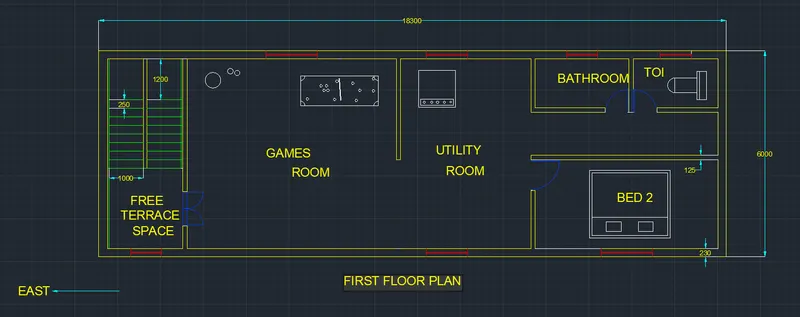
Type o for offset command and draw a vertical line from door line at a distance of 6100mm for the games room.
Again take o command for offset and draw a vertical line for the inner wall thickness of 125mm as the wall of games room.
Leave a opening for the next rooms.
Draw some entities of games room like pool game board, balls, football in games room as per the adjustable sizes.
Take circle command to draw a circles in drawing.
Leave the opening of 2637mm for entering into another room.
Type T for trim command and erase that 2 lines.
Take line command and draw a line from the games rooms wall at a distance of 3800 mm for the utility room as we are taking the length of utility room as 3800mm.
Type l foe line command and draw a line of 125mm from the utility room line as the inner wall of the room.
Draw a different types of structures like washing machine etc.
Type l for line command and take the horizontal distance of 18300 mm from the 1st upmost corner point of the structure as the total length of the plot is 18300mm.
Draw the vertical line from the last point of the 18300mm distance and take a vertical distance of 6000mm.
Complete the rectangular structure of first floor as the given plot size.
Type l for line command and draw inner lines as a distance of 230mm as the external walls.
Now take line command and draw a line from outer line of kitchen wall at a horizontal distance of 2738mm and draw a perpendicular line to that line at a distance of 1478mm for the bathroom.
The remaining block which is just besides the bathroom is for toilet as the dimensions of the toilet are 2459mm * 1478mm.
Type o for offset command and draw line which is parallel to the last vertical line at a distance of 5332mm and horizontal line from the last horizontal line at a distance of 2584 mm.
This is the bed room 2 which is made by the dimensions of 5332 mm × 2584 mm.
Use line, rectangle, and circle command for drawing the different entities of bedroom as well as toilet and bathroom.
Draw a bed for bedroom 2 by using the rectangle command of the suitable size.
Also draw the commode in the toilet by using circle and line command.
Now, we are taking the dimensions of doors as following -
main door D1 - 1000mm × 2000mm
bedroom door D2 - 900mm × 2000mm
bathroom door D3 - 700mm × 2000mm
toilet door D3 - 700mm × 2000mm
for the creation of bedroom door take line command and distance of 1000mm from the required point.
Leave 50mm distance from last point and create distance of 1000mm door.
Take centre, first point, second point type of curve command from home tab and draw a curve for the bedroom door.
For the creation of bathroom and toilet door, take line command and take a distance of 700mm from the leaving space of 50mm point and draw a door.
Again take a curve command from home tab and draw a curve from three point.
Now, we are taking the dimensions of windows as per following –
Entrance, toilet, bathroom window W1 = 900 mm × 1200 mm
Dinning and kitchen window W2 = 1200 mm × 1200 mm
Living room and bedroom window W3 = 1500 mm × 1200 mm
For the creation of windows, take line command and draw a distance of 900mm at a center of the entrance wall by leaving same distance from both sides.
Follow the same procedure for all the windows which are exist in the plan and provide the necessary distances as per plan.
Draw a line from the centre of all the windows as respective distances.
Using of layer properties.
For giving the different types of Colours we can use layer properties which is at a home tab.
Click on the layer properties and then click on the new layer and name it as walls and give a colour no 50(yellow) to the wall.
Again create a new layer and name it as stairs and select colour no 80 ( green ) for stairs.
Again create a new layer and name it as doors and select colour no 170 ( blue ) for doors.
Again create a new layer and name it as windows and select colour no 240 ( red ) for windows.
Dimensions -
Type un in command box for units.
The dialogue box will appear in which keep the length as a decimal and also keep the precision as 0.
And press ok.
Also type on the annotation on the home tab and press on the right corner arrow which is just besides the dimensions.
The new dialogue box will appear.
Keep the style as standard and click on the modify.
Firstly, select the line and change the colour of line as per required.
Then, select symbols and arrows and increase the size of the arrow as 120.
Also click on the text and change not only the colour of text but also increase the size of text as 140.
Now, go to primary units and change the unit format as a decimal.
Also change the precision as 0.
Press ok.
Give the dimensions to all walls and stairs, internal wall etc.
Click on the dimensions in the home tab and select single line text.
Click on the design and move cursor in downward direction at a certain height , the height which you wanted as a text height.
Type all types of texts as Games room, utility room, bedroom 2, bathroom and toilet etc.
Give design name as FIRST FLOOR PLAN.
Type QL in command box for q leader, the dialogue box will appear in which select the close arrow and no of lines as 2.
Draw a q leader from left side of drawing and text it as EAST.
Because it’s a front side of a plan and we have to give it as east facing.
RESULT -
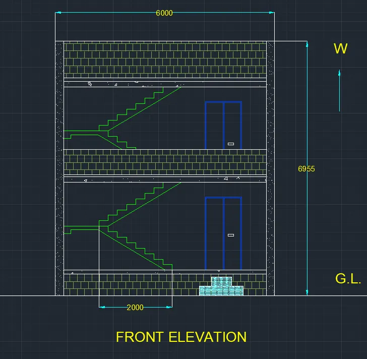
Step 3 - Creation of front elevation
For the front elevation,
Type l for the line command and draw a horizontal line of 6000 mm as the length of the plan is 6 meters.
Type o for offset command and select a horizontal line of 6m and make an offset to the upward side at a distance of 600mm for the sand filling.
Type o for offset command and make a line at a distance of 100mm from the 600mm line to the up direction.
Type o for offset command and make a offset at a distance of 2286mm to the upward side for the ground floor height.
Type o for offset command and draw a line from the ground floor line at a upward distance of 152.4mm for the slab.
We are taking the slab thickness is 152.4 mm.
Type o for an offset command and draw an offset at a distance of 30 mm from the slab line for the weathering course.
Type o for offset command and draw a line from the 30mm line at the upward direction at a distance of 2286 mm for the first floor height.
Type o for offset command and draw a line from the first floor line at a upward distance of 152.4mm for the slab.
We are taking the slab thickness is 152.4 mm.
Type o for an offset command and draw an offset at a distance of 30 mm from the slab line for the weathering course.
Type o for offset command and make an offset of 1000mm from the 30mm line at up direction.
Type L for line command and draw two vertical lines from that 6000 mm line and complete the rectangular structure for front elevation.
Type TR for trim and erase all unnecessary lines of the drawing.
Type o for offset command and draw an offset from the very first and very last vertical line to the distance of 230 mm as they are the external walls of the structure.
Type TR for trim and erase all unnecessary lines of the drawing.
Creation of stairs
Take line command and draw a vertical line from the inner side of the left wall at a distance of 1200 mm for the landing of stairs.
Type o for offset command and draw an vertical offset at a distance of 2000 mm at right side from the landing line.
For stairs we are taking riser as 142.87mm and thread distance as 250mm.
Take line command and from the bottom point of the 2000mm distance line draw a vertical line at a distance of 142.87 mm as a riser and on the continuation of that draw a horizontal line on the left side at a distance of 250 mm as a thread.
Continue this step for 8 times as a total no of steps are 8 and complete the staircase.
Draw a horizontal line on a left side at from the last step at a distance of 1200mm as a landing of staircase.
From the last point of the staircase again draw a vertical line at a distance of 142.87 mm as a riser and on a continuation of that draw a horizontal line on the right side at a distance of 250 mm.
Now continue this process for 8 times as total steps are 8 but they are moving in opposite direction as compared to the first steps.
Make a thickness of 100 mm for the landing line and continue that thickness for entire staircase.
Copy the entire staircase and paste it in the first floor at a same vertical axis.
Leave the distance of 640 mm from the right end and draw a vertical line from that point at a distance of 2000 mm as the height of the door and on the continuation of that line draw a horizontal line on the left side at a distance of 1000mm as the length of the door.
Complete the rectangle of the door with the dimension of 1000mm 2000mm.
Divide the whole door in two parts by vertically.
Type REC for rectangle command and draw a small rectangle as a handle for door.
Copy the whole door structure and paste it in the first floor at vertical axis.
Extend bottom 6m line horizontally from right side and left side as a ground level.
Type REC for rectangle command and draw 2 rectangles as per required size below the door at a entrance.
Type o for offset command and draw a horizontal offset from the first floor slab line to the up direction at a distance of 800 mm for the balcony structure.
Click on the dimensions and draw the horizontal and vertical dimensions respectively.
As we are designing in the same tab so dimension setting is done already.
The total vertical distance is 6955mm.
Click on the layer properties for colours which are already choose.
Select the staircase and gave the colour no 80 and also select the doors and gave the colour no as 170 respectively.
Hatching
Type HAT for hatching and then there will be a dialogue box in which we are going to take certain patterns and colours for hatch.
Select the pattern of AR-B816 and select a colour for that hatch pattern.
Select the bottom rectangular part and also middle rectangle ( between 2 floors ) and upmost huge rectangle and enter.
As these rectangles are representing the gallery and terrace in plan respectively.
Then, type HAT for hatch command and select the hatch pattern of AR-CONC and take scale of 2 for this and press ok.
Select the 2 upmost left and right columns and enter.
Again hake hatch command and select CONGLOM5 and then select the slab portion and enter.
Click on text and select single line text and give the diagram name as FRONT ELEVATION.
And also text as G.L. and west for direction.
RESULT –
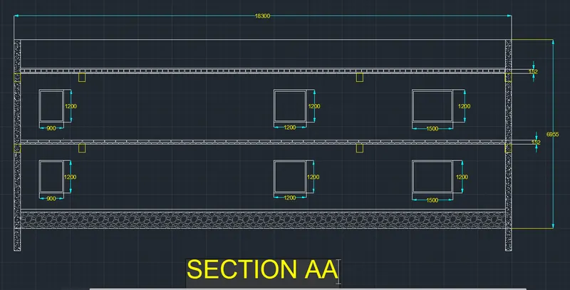
Step 4 - Creation of section.
For the creation of section we have to take all the horizontal lines projection from the front elevation drawing to the right side.
Because the dimensions and the structure is same as we are taking the section of a plan from left side.
Now, take line command and draw a vertical line and on the continuation of that line draw a horizontal line at a distance of 18300 mm.
As a total length of plan is 18300mm.
Type TR for trim command and erase all the unnecessary lines and projecting lines for plan.
Now move the ground floor plan to the upper side of a section and place it as perfectly parallel at vertical axis.
Now, we are taking the AA section as per given ground level plan. So, we are taking the projections of all windows which are available in section.
Also we are taking the projection of column from ground floor plan to the section plan.
Type TR for trim command and erase all the unnecessary lines of projection.
Now, we are taking the dimensions of windows as per following –
Entrance window W1 = 900 mm × 1200 mm
Dinning window W2 = 1200 mm × 1200 mm
bedroom window W3 = 1500 mm × 1200 mm
Click on the dimensions and draw the horizontal and vertical dimensions respectively.
As we are designing in the same tab so dimension setting is done already.
The total vertical distance is 6955mm.
Give proper dimensions to windows also.
Hatching
Type HAT for hatching and then there will be a dialogue box in which we are going to take certain patterns and colours for hatch.
Select the pattern of AR-B816 and select a colour for that hatch pattern.
Also select slab thickness and give the respective hatch properties.
Click on text and select single line text and give the diagram name as SECTION AA.
RESULT –
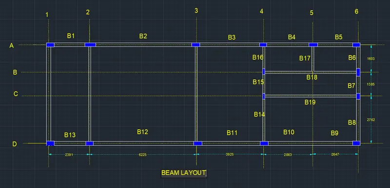
Step 5 - Creation of Beam Layout
Take X line command to draw a horizontal infinite line and also on the Ortho mode for 90 degree
Line.
With x line draw a vertical line too for vertical distances.
Type o for offset command and draw a line parallel to vertical line at a distance of 230mm as we are taking wall thickness of 230 mm.
Type o for offset command and draw an offset at a distance from 2203mm from wall inside the design.
Type o for offset command and draw a vertical line from door line at a distance of 6100mm for the living area.
Again take o command for offset and draw a vertical line for the inner wall thickness of 125mm as the wall of living room.
Take line command and draw a line from distance of 3800 mm
Type l for line command and draw a line of 125mm from the kitchen line as the inner wall of the kitchen.
Type l for line command and take the horizontal distance of 18300 mm from the 1st upmost corner point of the structure as the total length of the plot is 18300mm.
Draw the vertical line from the last point of the 18300mm distance and take a vertical distance of 6000mm.
Complete the rectangular structure of plot size.
Type l for line command and draw inner lines as a distance of 230mm as the external walls.
Now take line command and draw a line from outer line of kitchen wall at a horizontal distance of 2738mm and draw a perpendicular line to that line at a distance of 1478mm for the bathroom.
The remaining block which is just besides the bathroom is for toilet as the dimensions of the toilet are 2459mm * 1478mm.
Type o for offset command and draw line which is parallel to the last vertical line at a distance of 5332mm and horizontal line from the last horizontal line at a distance of 2584 mm.
This is the bed room which is made by the dimensions of 5332 mm × 2584 mm.
Do not leave spaces for doors and openings because this is the beam layout.
Now type LT for line type and change the line as dotted line and press ok.
For beam layout we have to draw a dotted line from every wall which represents a beam structure.
Take line command and draw a dotted line from between the outer wall at a distance of 115mm because the total thickness of wall is 230mm.
And also draw a line from the inner wall at a distance of 57.5mm as the wall thickness is 125mm.
Extend all the dotted line outside of the structure.
Type REC for rectangle command and draw a required size of the column for the beam layout.
Copy the column and move the column at a required places.
Type HAT for hatching and select SOLID pattern in hatching and choose a colour no 170 for hatching.
Select all the columns and enter.
Click on the dimensions and give proper dimensions to all beams.
Click on text and select a single line text.
Give all beams name as B1, B2, B3, B4, B5, B6, B7, B8, B9, B10, B11, B12, B13, B14, B15, B16, B17, B18, B19 Respectively.
Also give the sequence for outer line as 1,2,3….and A,B,C,,,,, etc.
And give the design name as BEAM LAYOUT.
RESULT –
Step 6 - Creation of Column Layout
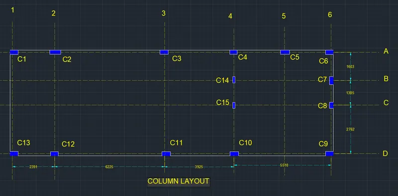
For the creation of column layout we have to take projection of all dotted lines which are available in the beam layout.
Take all horizontal dotted lines from the beam layout.
Move the beam layout structure at a upward side of the column layout and also take the vertical projections of beam layout in the downward direction.
Now , in the beam layout select all the columns in the design and only select the outer line which is touching all the columns.
And paste all the copied columns and line in the respective drawing.
Not only the columns but also copy the hatching part of the columns.
Click on the dimensions and give proper dimensions to all beams.
Click on text and select a single line text.
Give all columns name as C1, C2, C3, C4, C5, C6, C7, C8, C9, C10, C11, C12, C13, C14, C15 respectively.
Also give the sequence for outer line as 1,2,3….and A,B,C,,,,, etc.
And give the design name as COLUMN LAYOUT.
RESULT -
Step 7 - Creation of Footing Layout
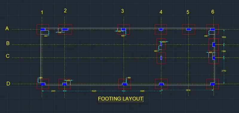
For the creation of footing layout we have to take projection of all dotted lines which are available in the beam layout.
Take all horizontal dotted lines from the beam layout.
Move the beam layout structure at a upward side of the footing layout and also take the vertical projections of beam layout in the downward direction.
Now, in the beam layout select all the columns in the design and only select the outer line which is touching all the columns.
And paste all the copied columns and line in the respective drawing.
Not only the columns but also copy the hatching part of the columns.
Now, for drawing the footing we have to take line command.
Draw a line 400mm away from each and every column by horizontally and vertically.
And create a rectangle which is away by 400mm from all direction of column.
Repeat this procedure from all columns.
This rectangle is known as footing.
Select all footings and give colour no 240 by using layer properties.
Click on the dimensions and give proper dimensions to all beams.
Click on text and select a single line text.
Also give the sequence for outer line as 1,2,3….and A,B,C,,,,, etc.
And give the design name as FOOTING LAYOUT.
RESULT -
ALL RESULTS =