Project 1 - Controlling a DC motor using PWM and monitoring its Running status
Project 1 - Controlling a DC motor using PWM and monitoring its Running status :
Overview of the Project:
Implement a system on the simulator for controlling a DC motor using L293 motor driver, monitor its status and print the running status of motor on the LCD Display.
Goals:
- Implement a system on simulator for Controlling the DC motor using L293 motor driver.
- Displaying the running status of DC motor on the LCD display.
Key Highlights of the Project:
- The DC motor can be controlled by using L293 motor driver.
- The speed of a DC motor can be controlled by varying its input voltage, for doing this is to use PWM (Pulse Width Modulation).
- L293D IC is a typical Motor Driver IC which allows the DC motor to drive on any direction.
Deliverables of this project:
- Implement the system for controlling DC motor.
- Controlling the speed of the DC motor using PMW.
- Displaying the present running status of DC machine on LCD display.
Expected Outcomes:
- Implement a system on simulator to control a DC motor using PMW
- Monitoring the running status of the DC motor using L293 motor driver which allows the DC motor to drive on any direction.
- Running status i.e. on which direction the DC motor is running is to be displayed on the LCD screen.
Working with L293 motor driver :
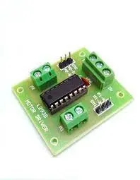
A motor driver is an integrated circuit chip which is usually used to control motors in autonomous robots. Motor driver act as an interface between Arduino and the motors . The most commonly used motor driver IC’s are from the L293 series such as L293D, L293NE, etc. These ICs are designed to control 2 DC motors simultaneously. L293D consist of two H-bridge. H-bridge is the simplest circuit for controlling a low current rated motor. We will be referring the motor driver IC as L293D only. L293D has 16 pins.
As the value of OCRO increases the ON time also increases in non investing mode of phase correct PWM mode.
Int this project we are having 8 bits PWM
which means 256 bits, 25% of 256 bits .
HARDWARE circuit :
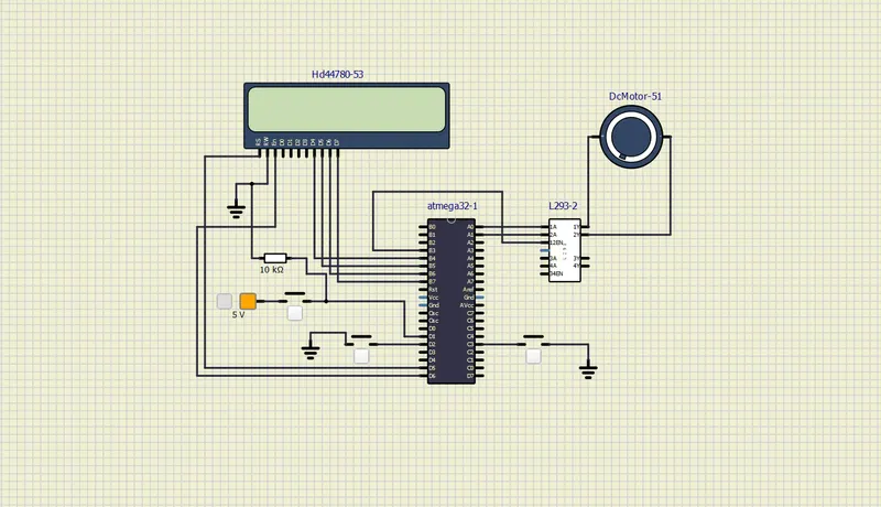
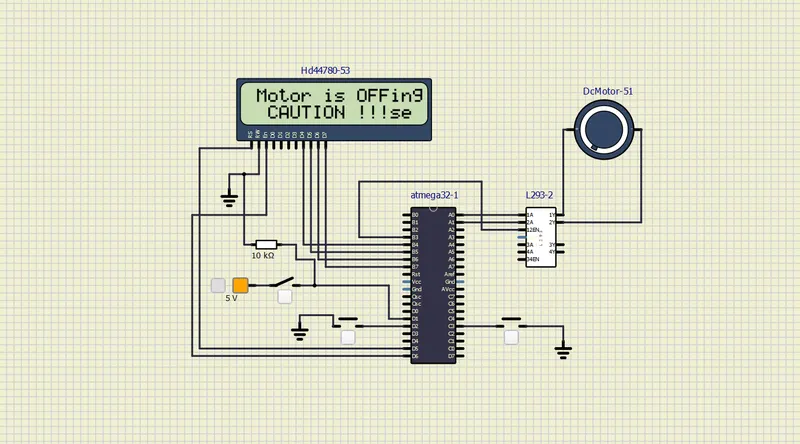
Motor off simulation :
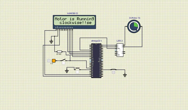
Simulation clockwise :
Simulation anticlockwise :
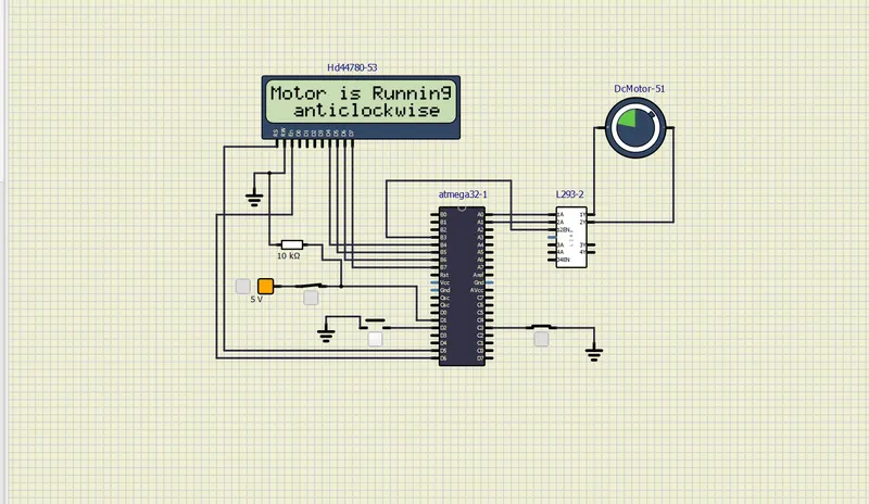
Speed of the motor increases as PUSH BUTTON PRESSES :