Project 1_Comparative study of different storey buildings for Seismic forces
- MODELLING OF 25 STORY BUILDING WITH THE SPECIFIED PROPERTIES USING ETABS
- AIM :
-
Model a 25 storey building on ETABS with structural properties as specified below. Ground floor or plinth floor level can be taken at a height of 1.5 metres from the base. Each of the successive 25 storeys has a storey height of 3 metres.
- SOFTWARE USED :
- ETABS : EXTENDED THREE DIMENSIONAL ANALYSIS OF BUILDING SYSTEM this software is used for design and analysis of buidings system .
- It mainly used for structures like high rise buildings steel and concrete structures
- IS CODE USED IN THE PROJECT :
- IS 800 :2007 FOR STEEL DESIGN
- IS 456 :2000 FOR CONCRETE DESIGN
- GIVEN INFORMATION :
-
Structural Element Sizes :
- Beams : 300 × 400 mm
- Columns : 800 × 800 mm
- Slab : 150 mm thick
Material Properties :
- Grade of Concrete : M30
- Grade of Steel Reinforcement Bars : Fe 415
Loading :
- Dead Load on beams from infill wall : 10 kN/m (Let us assume the same for roof floor in view of parapet)
- Live load on floor : 3 kN/m2 (Let us assume the same for roof floor)
a) Buildings are assumed to be pinned at the base
b) All columns in all storey are of the same size
c) All beams in all storeys are of the same size
d) Building is located on Soil type-II and in Zone-III. Assume other factors if required.
- CHECK THE FOLLOWING THINGS :
- Check if the translational fundamental natural period of vibration in both the x and y direction is approximately: Tx1= 4.4 second Ty1">Ty1= 4.2 second
- Check if the following provision in Table 5 of IS 1893 (part 1) – 2016, on torsional irregularity satisfied:
- Check if the two provisions of clause 7 in Table 6 (shown below) of IS 1893 (part 1) – 2016, regarding vertical irregularity is satisfied
- Check if provision on inter-storey drift limitations in clause 7.11.1.1 satisfied. Please note that this check is for Serviceability Limit State and hence is for situation when stucture is subjected to unfactored seismic base shear
- PROCEDURE :
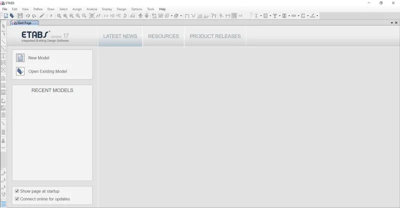
- click on ETABS SOFTWARE then ul of software is open shown below
- STEP 1
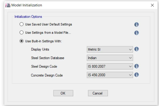
- Click on NEW MODEL then model initialization tab is open
- provide the display units , steel and concrete IS CODE as shown below
- click OK
- STEP 2
- After that NEW MODEL QUICK TEMPLET tab is open
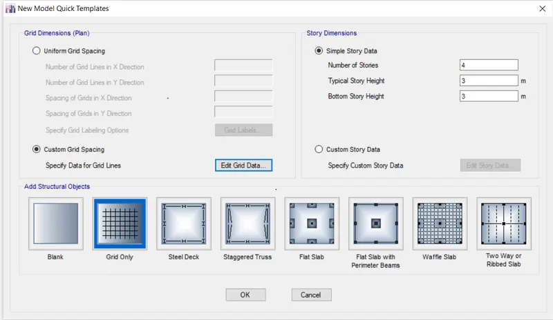
- in that click on CUSTOM GRID SPACING and click on EDIT GRID DATABASE
- In this box we set the 5 no of grids in x direction and 5 no of grids in y direction having distance is 4m.
- as shown below
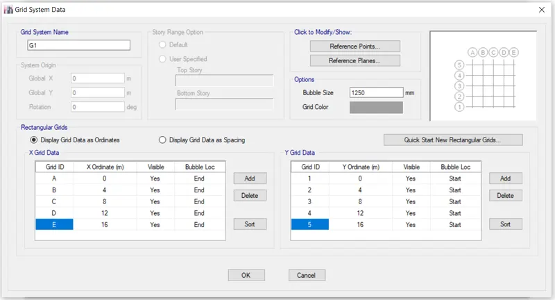
- click ok
- STEP 3
- in that click on CUSTOM GRID SPACING and click on EDIT GRID DATABASE
- In this box we set the 5 no of grids in x direction and 5 no of grids in y direction having distance is 4m.
- as shown below
-
- click ok
- STEP 4
- Click on custom story data
- Give the first level as plinth level and another level is story 1 , then story 2 till story 25
- give the hight of plinth is 1.5 m
- we dont provide slab on plinth as per shown below
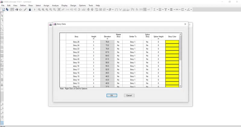
- click ok
- STEP 5
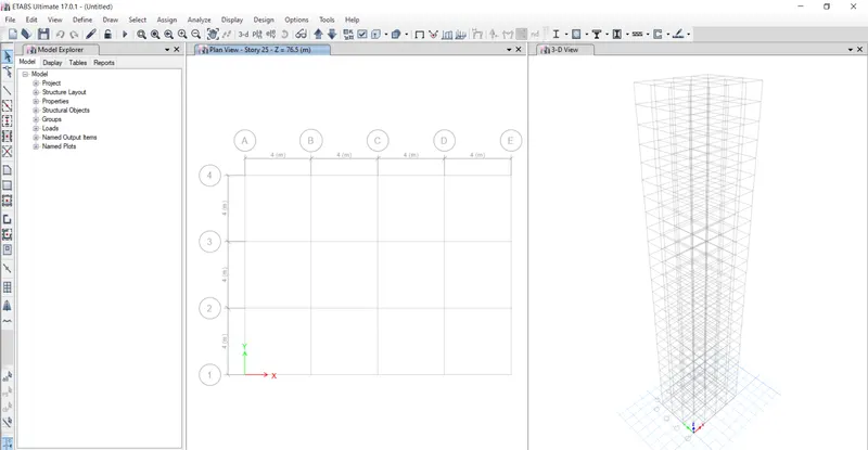
- After that plan and eleveation of each story are shown
- shown below
- STEP 6
- Applying the material properties to the frame
- so that click on define tab
- then dialogbox is open
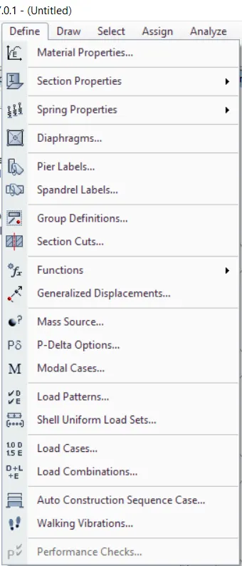
- from that click on material properties
- then click on ADD MATERIAL
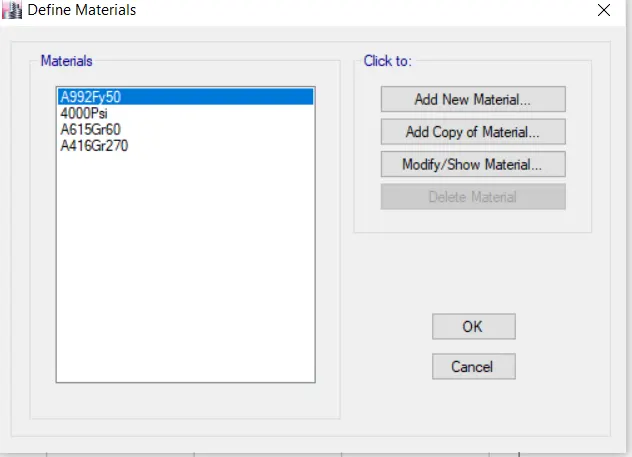
- click on add new material
- first add concrete material
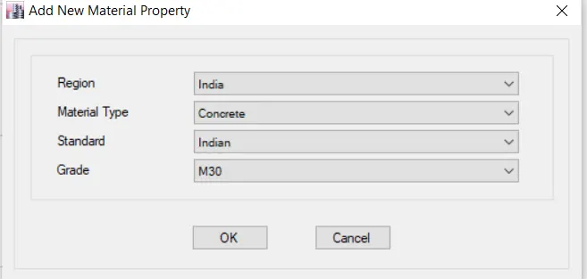
- click OK
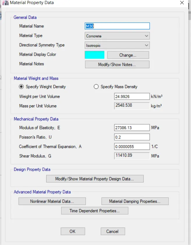
- again click OK
- after that ADD steel material
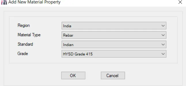
- click ok
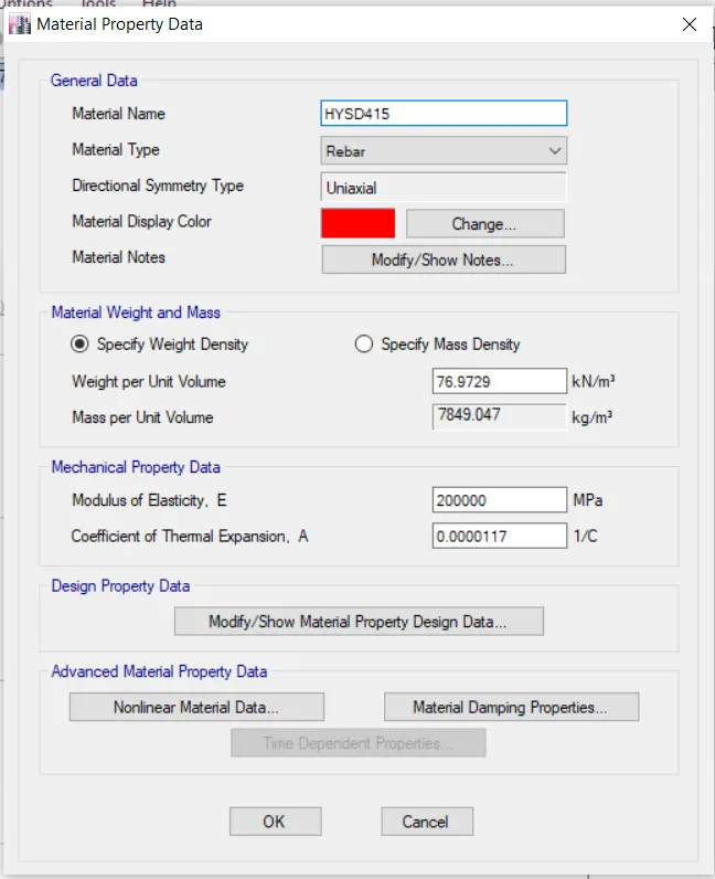
- click ok
- now both steel and concrete material is added
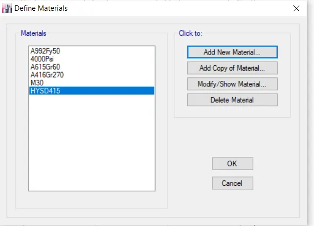
- click ok
- STEP 7
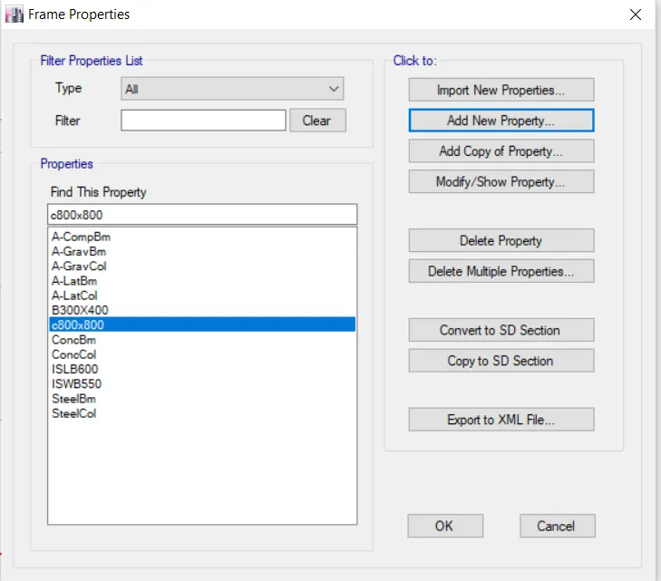
- Then go for section properties
- click on frame section
- and create a new beam section shown below
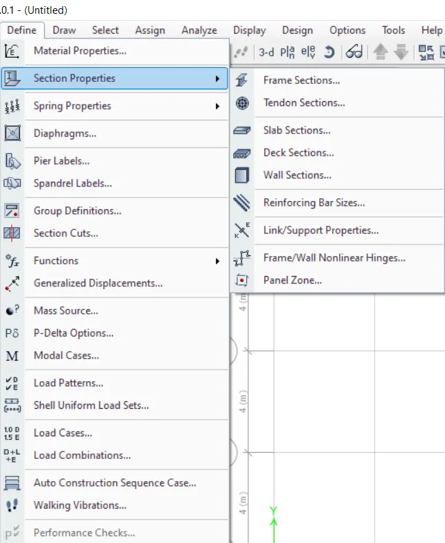
- click on frame section
- then new dialogbox is open shown below
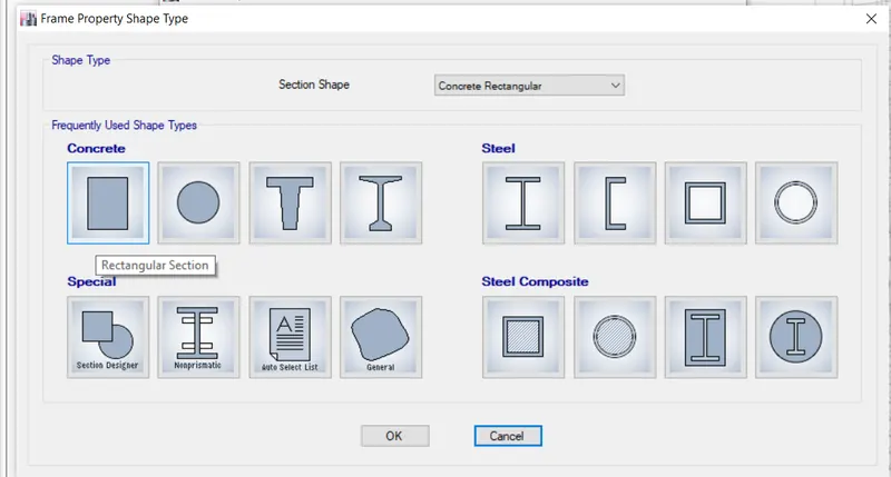
- select the concrete rectangle
- click on rectangular section
- click ok
- Then new dialogbox is open
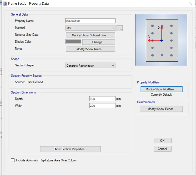
- give the name as b300x400
- material as M30
- depth of beam is 400 and width is 300
- shown below
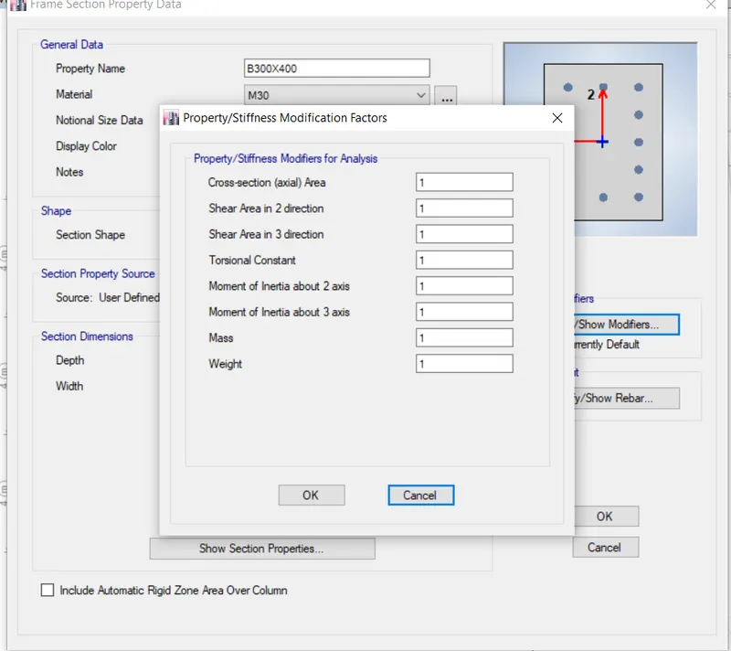
- from properties modifires
- for MI of the beam we consider only 30 % for earthquake design but that applicable only for ultimate design .
- but here we do only analysis so that we cant change any values .
- click OK
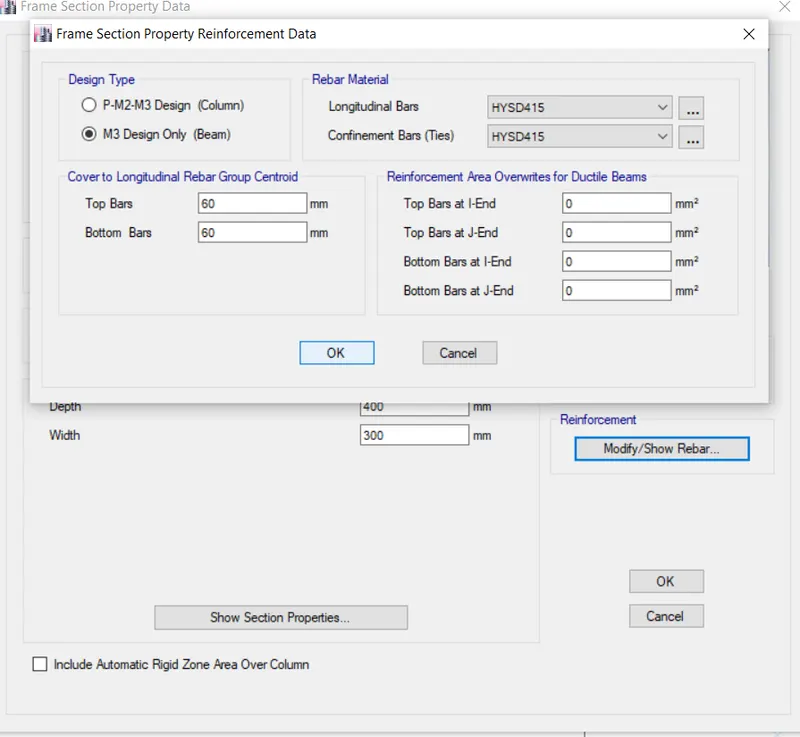
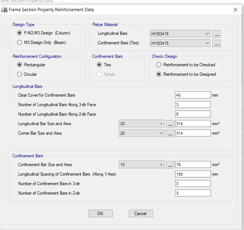
- click on modify show rebar
- new dialogbox is open
- from that change design type
- and also change rebar material as HYSD415 shown below
- click ok
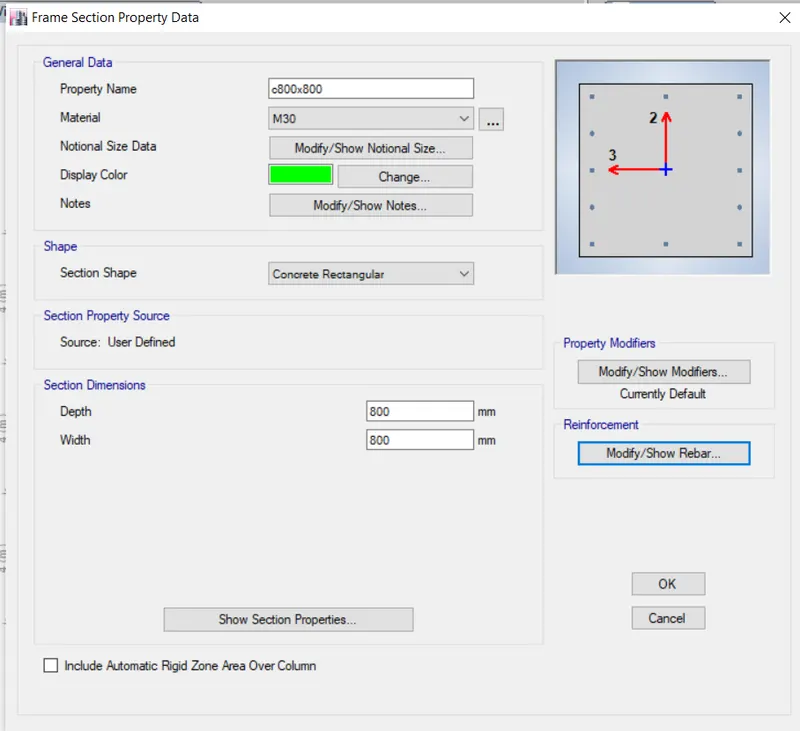
- now do same process for column frame shown below
- click OK
- STEP 8
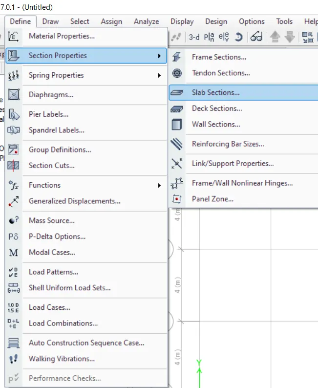
- Then define slab
- so that click on define then section properties then slab section
- then new dialog box is open
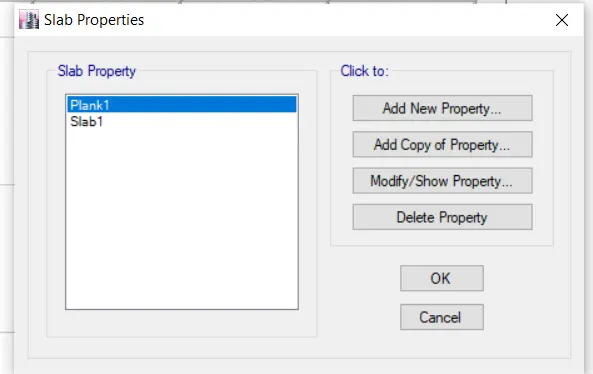
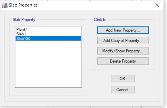
- from that click on add new properties
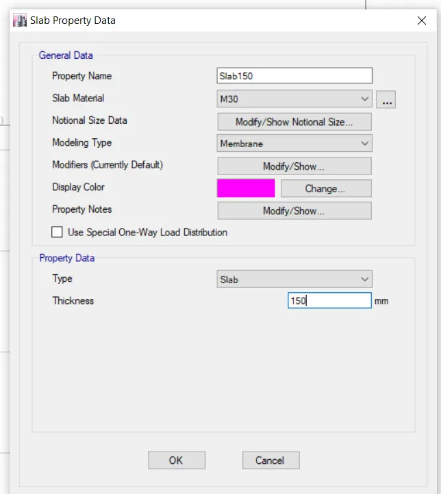
- give the name of slab is slab150
- slab material is M30
- here we put modeling type as membrane becouse to avoid T section and L section
- then give the slab thickness is 150 ........ ( which is given in question )
- click OK
- Click OK
- STEP 9
- Give the load patterns
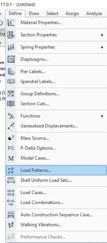
- so that click on define tab
- then click on load pattern
- Then new dialogbox is open
- where dead load and live load alrady there
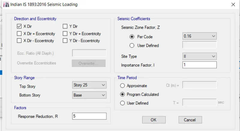
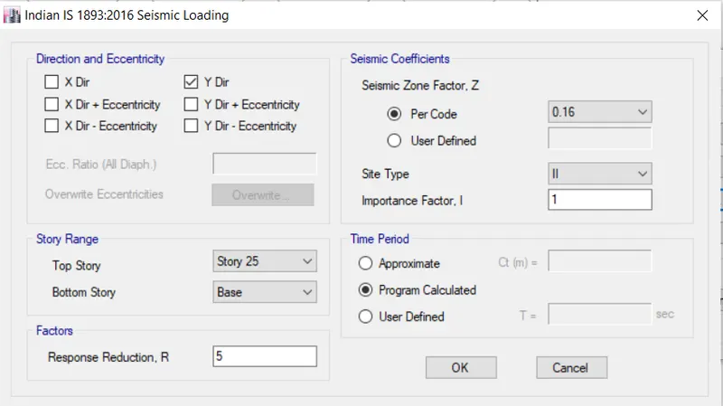
- then add wall load also add EQX and EQY load shown below
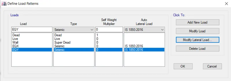
- then click on EQX
- then modify lateral load
- dialogbox is open there as shown below
- click OK
- again Click ON EQY
- again click on modify lateral load
- then click ok
- STEP 10
- Then go to difine tab
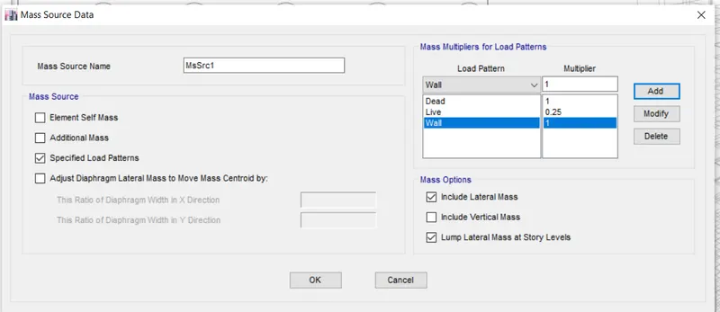
- click on mass source
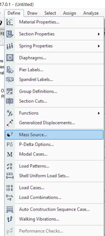
- then one new dialogbox is open
- shown below
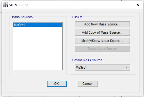
- then click on modify shown mass source
- again new dialogbox is open
- from that select the specified load pattern
- then give the load pattern as shown below
- click ok
- STEP 11
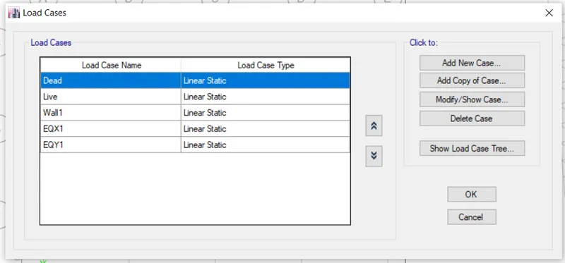
- check the load cases
- for that go to the define tab
- click on load cases
- new diaogbox is open as per shown below
- then click ok
- STEP 12
- Give the load combination
- agin go to the define tab
- click on load combination
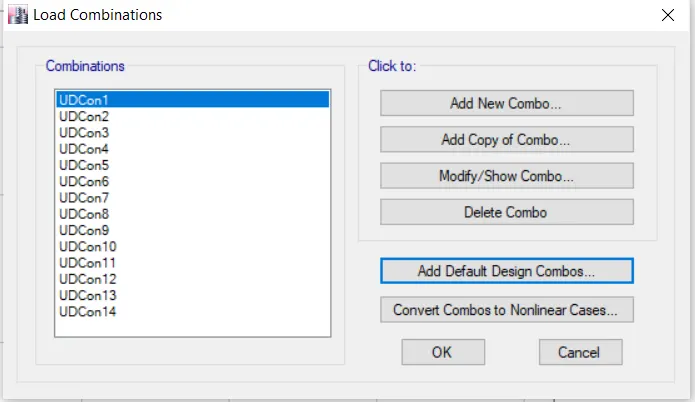
- then load combination dialogbox is open
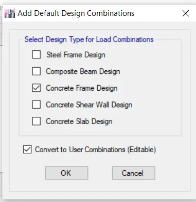
- from that click on add design load combination
- agian new dialogbox is open as per shown below
- click ok
- again click ok
- STEP 13
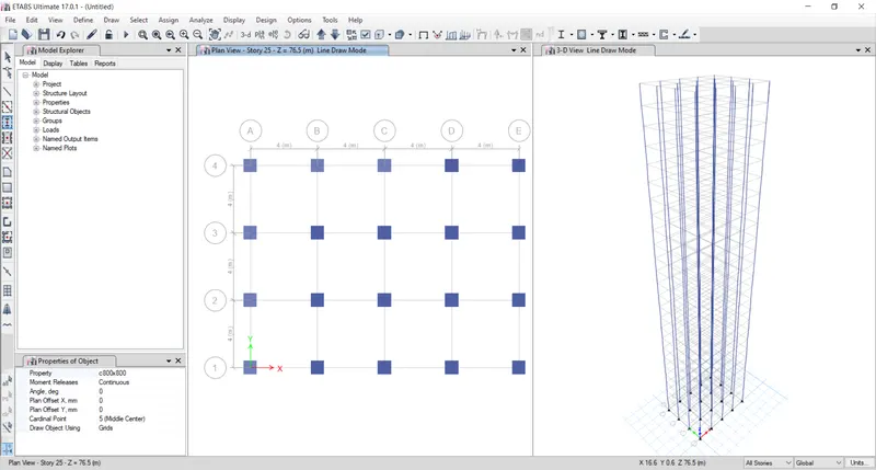
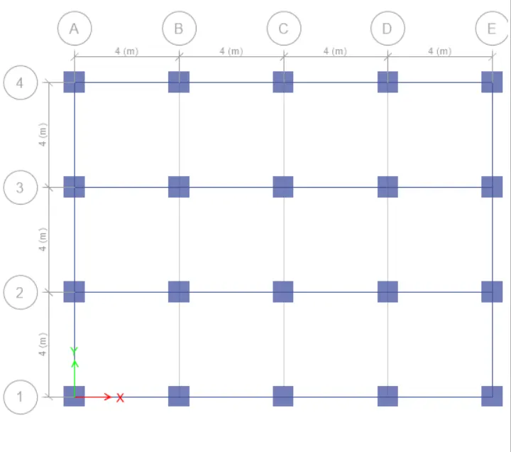
- draw the column
- so that do to the quick draw
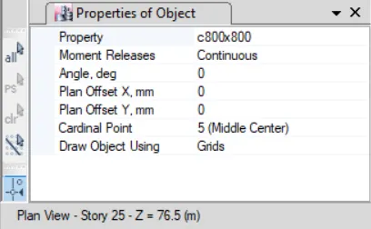
- one properties dialogbox is open
- select the column as shown below
- then mark the column shown below
- STEP 14
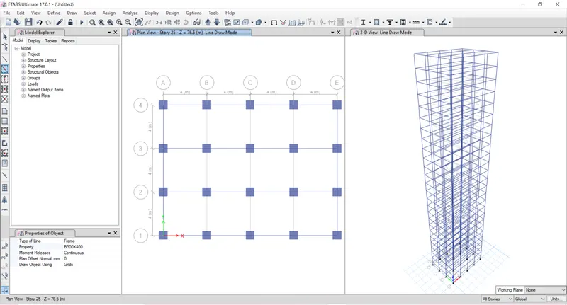
- Draw the beam
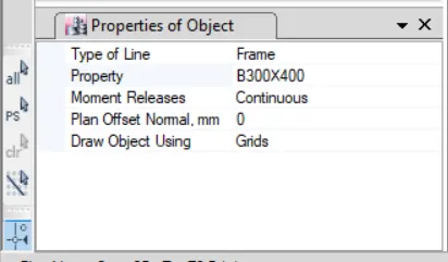
- so that go to the quick draw column / beam option
- select the B300X400
- and draw it shown below
- STEP 15
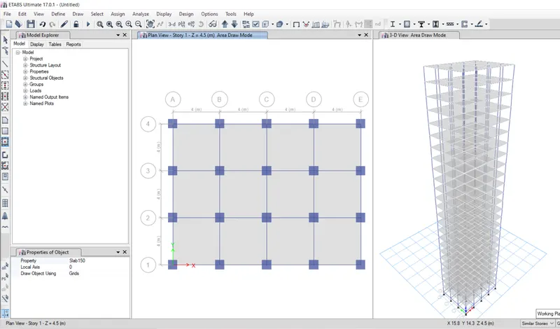
- Draw the slab
- so that click on set plan view
- one dialogbox is open
- select the first story which is master story
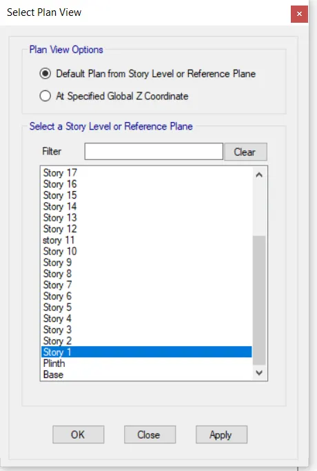
- click on apply and then ok
- then go to the quick draw floor option
- selct the slab150
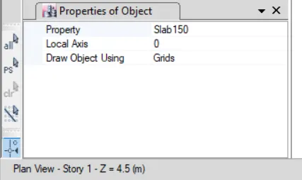
- and then draw the slab
- STEP 16
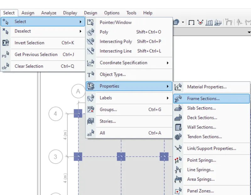
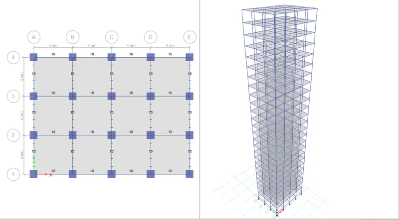
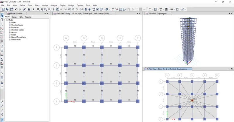
- select all beams and asign frame loads
- so that click on select tab
- then click on properties
- and frame section
- one new dialogbox is open
- in that select the beam as B300x600
- as shown below
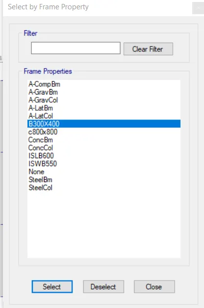
- click on select
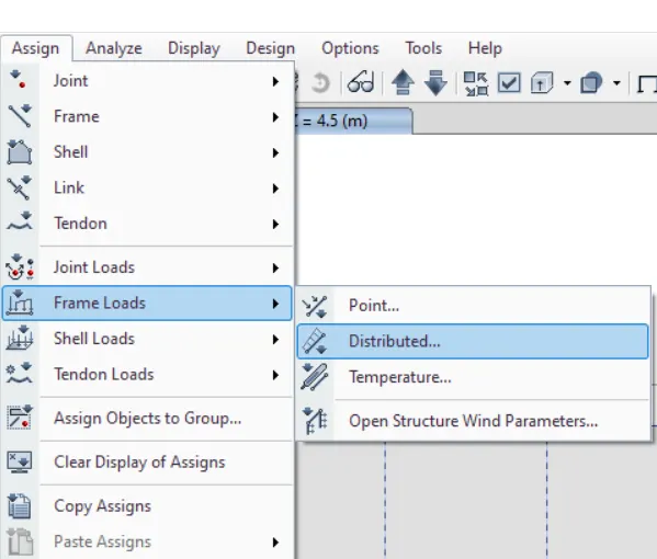
- then asign frame loads click on asign tab
- then click on frame loads
- then distributed frame load
- then one dialogbox is open
- from that select the wall load
- and give the value of load is 10
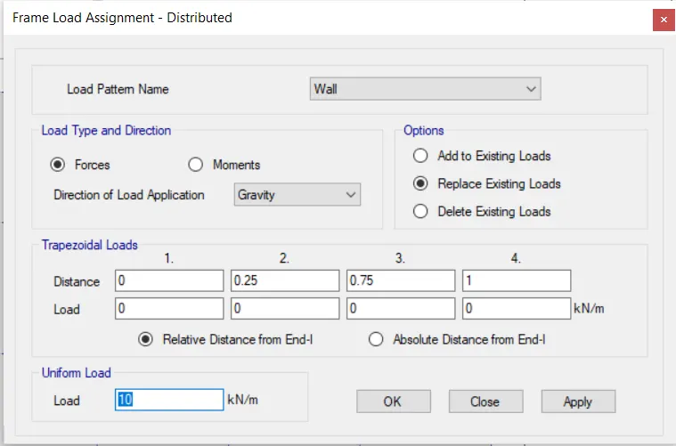
- click on apply
- and then ok
- STEP 17
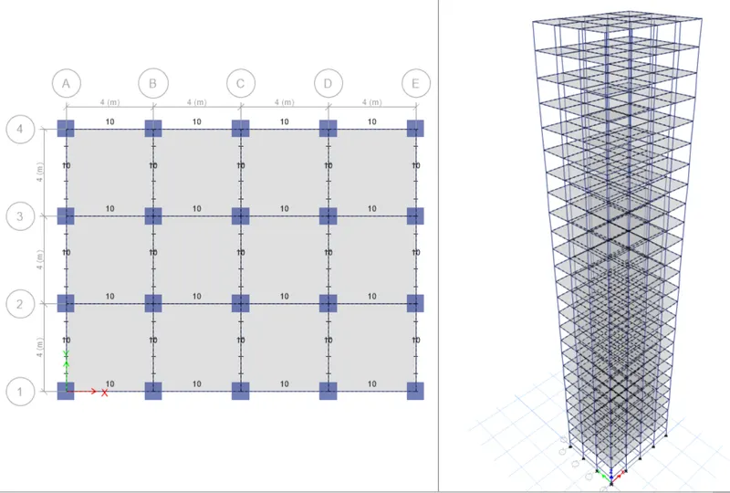
- now select the slab
- so that again go to the select tab
- click on select , then properties , then slab selection as shown below
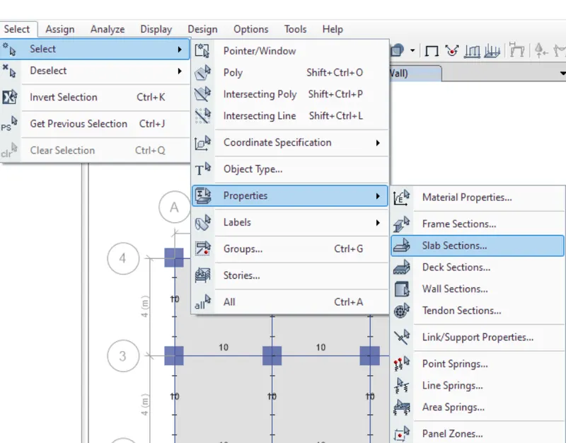
- then new dialogbox is open
- from that click on slab150
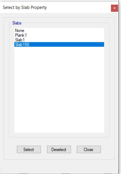
- select it and then close it
- STEP 18
- apply uniform shell loads
- so that
- click on asign tab
- from that click on shell loads then uniform
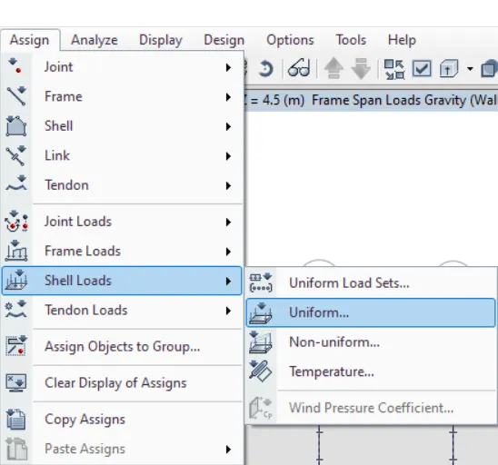
- one dialogbox is open
- from that select the load pattern as live load
- and give the value of live load as 3 kN/m^2
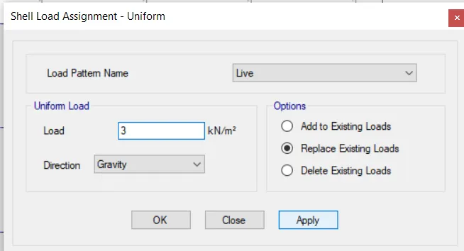
- Click on apply and then ok
- STEP 19
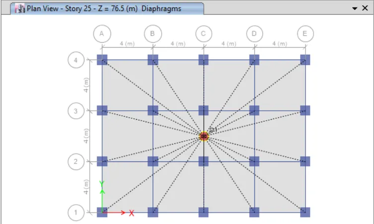
- Select the all slab again
- after selection
- select diaphragms
- for that
- click on asign tab , then click on shell , then diaphragms
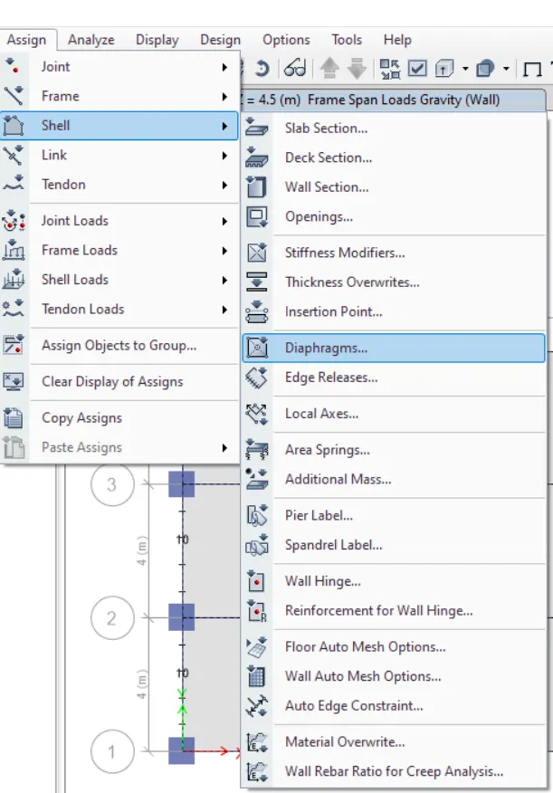
- then new dialogbox is open
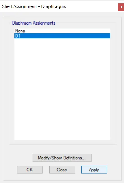
- click on D1
- then apply and ok
- center of mass is automatic calculated by using diaphragms properties
- STEP 20
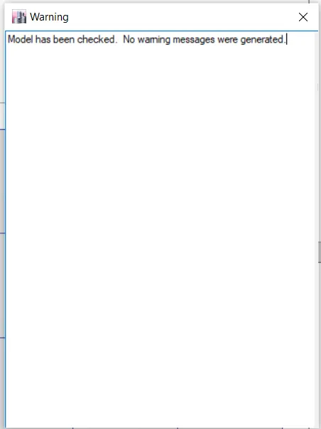
- Check the model
- so that go to the analyze tab
- click on check model and check it
- STEP 21
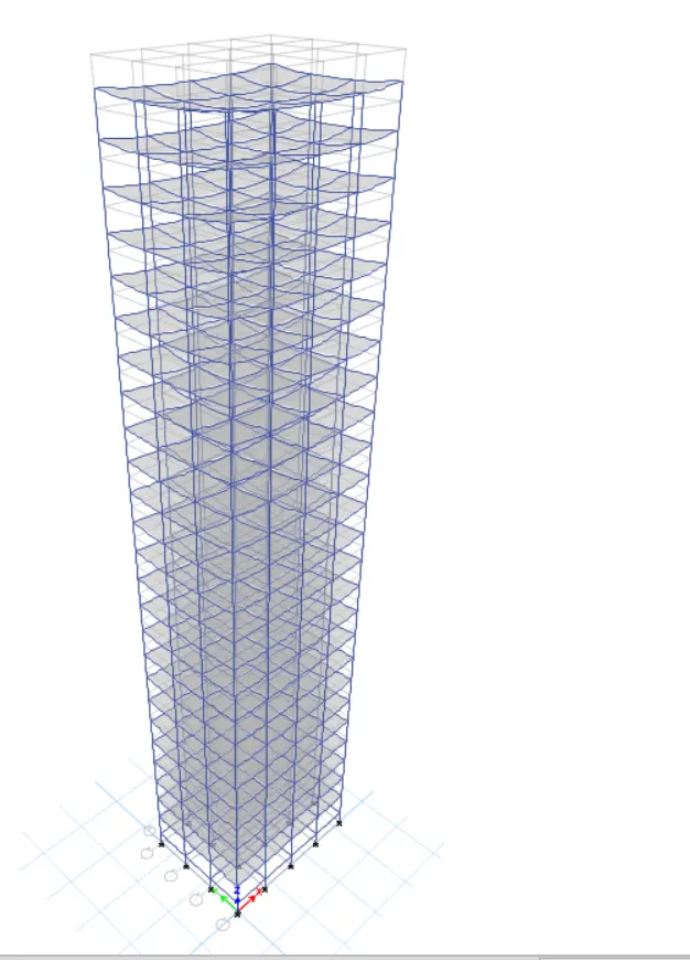
- ran analysis
- in this stage structure is ready for analysis
- RESULTS :
- CHECKS :
- 1 CASE :
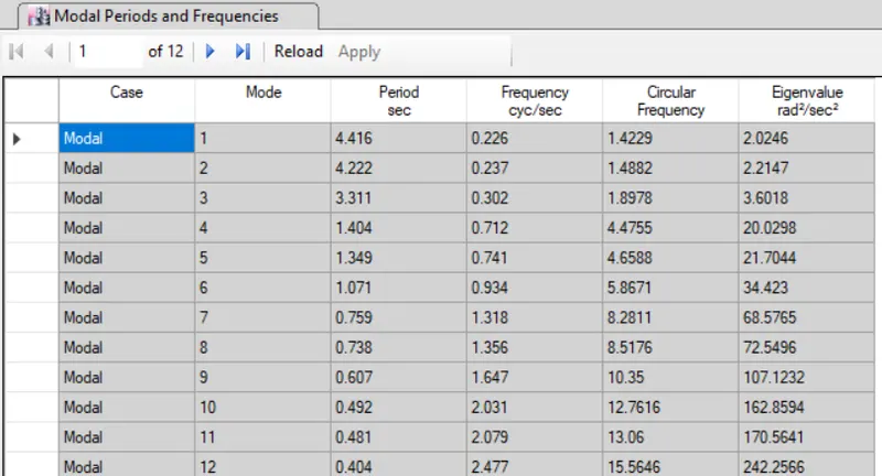
- Check if the translational fundamental natural period of vibration in both the x and y direction is approximately: Tx1= 4.4 second Ty1">Ty1= 4.2 second
- ABOUT RESULTS :
- Fundamental translational natural period in X direction is 4.416
- Fundamental translational natural period in Y direction is 4.222
- its near about same
- 2 CASE
- Check if the following provision in Table 5 of IS 1893 (part 1) – 2016, on torsional irregularity satisfied:
- The natural period corresponding to the torsional mode of oscillation must be less than the two fundamental translational modes of oscillation along each principal plan directions.
- ABOUT RESULTS :
- YES, mode 3 (3.11 ) is less than mode 2 (4.22) and mode 1
- 3 CASE
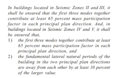
- Check if the two provisions of clause 7 in Table 6 (shown below) of IS 1893 (part 1) – 2016, regarding vertical irregularity is satisfied
-
- CONDITION 1 :
- YES , Mode 1 is occupies 80 % of mass of the building so no need to add another mode .
- CONDITION 2 :
- NO , Difference between x and y direction time period is not 10 %
- 4 CASE
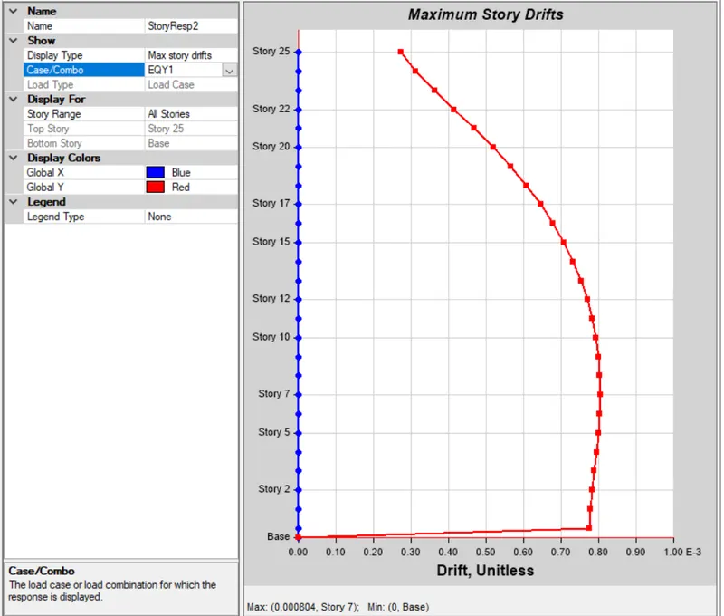
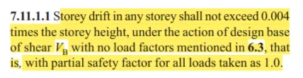
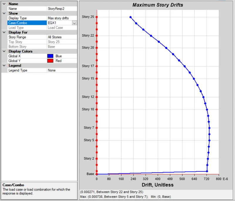
- Check if provision on inter-storey drift limitations in clause 7.11.1.1 satisfied. Please note that this check is for Serviceability Limit State and hence is for situation when stucture is subjected to unfactored seismic base shear
- ABOUT RESULTS :
- EQX
- EQY :