Project 1 : CFD Meshing for Tesla Cyber Truck
Aim & Objective:
For the given model, check and solve all geometrical errors and Assign appropriate PIDs. Perform meshing with the suitable Target length and element Quality criteria
Target lengths for the different parts of a model can be decided by your own. Finer mesh will give good results and will compromise with the longer processing time.
Procedure:
Following are the stepwise procedure and model approach towards project;
- First of all we import the raw geometry on which we have to work and then analyze those to see what are the errors present in it
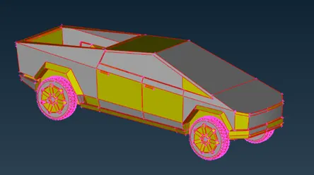
Fig 1. Raw geometry
- We can see there are many single cons present in geometry or we can clearly say there are only single cons present in geometry so first we do the topo there and lets see where we have to work. After applying topo we can see many single cons are solved but if we see there are many faces are also missing which we can see below.
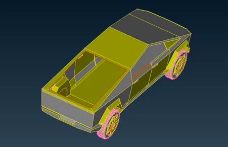
Fig 2. Missing faces
Also we can see there are many other errors present like glitch of overlapping surface, penetration of surfaces, extra cons and hot-points, PIDs not assigned proper, missing faces etc. we can see those bellow
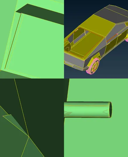
Fig 3. Errors in geometry
- Now as we found the errors in geometry now lets work on it, so first we cut the geometry in half by using delete option.
- After cutting we start to clear the geometry, which first we create the missing faces.
- Then we assign the PIDs to particular geometry, we can see ethe assigned PIDs below;
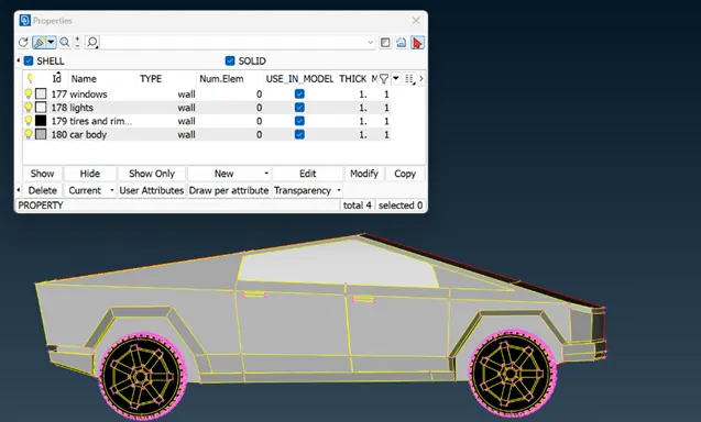
Fig 4. Assigned PIDs
- As after assigning PIDs we will get the proper view now we use the cut option to create the cut where needed and delete the extra cons or cuts present in geometry. Likewise using the cut, delete and face create option we clean the geometry.
- Now some parts are bit tricky here, if we see body, windows and lights they are not much more tricky to cleanup but if we see in tire part there are cons present nearer to each other, which will affect our mesh we can see those in below,
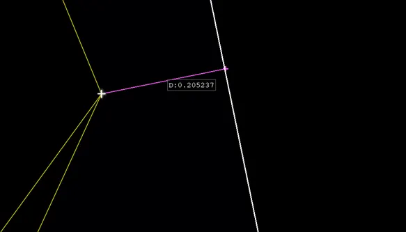
Fig 5. Before cleanup tire nearer points
We can see in above image the distance between con and node is 0.2 which will not acceptable during mesh because mesh will get more fine and consumes more computational power which will be waste because while doing aerodynamic study on car we don’t need to focus more on tires,
So, what we do is we enlarge the particular gap by using cut, delete and create option,
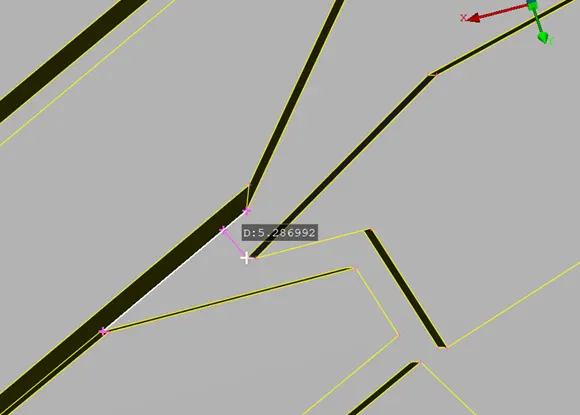
Fig 6. Post cleanup measurement
in above image we can see after clean up the distance between those cons and point is increased to 5mm.
- Now as we cleaned the geometry lets do the symmetry of half body, by using transform copy option where we select the whole body entities and then select the 3 points as we select three points plane option and then do the middle click which gives us the complete car body and successful symmetry operation.
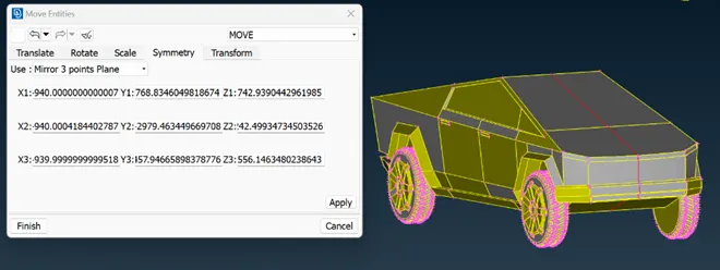
Fig 7. Car symmetry
- Now as our symmetry is done lets go for mesh for that we have to define different target length for different parts, we have to set these target length based on the area more focused to aerodynamic and also we have to look at minimum distance between nods and cons. Below are the target lengths we choose for our car body PIDs.
- For Body 5mm target length
- For Windows 5mm target length
- For Light 4mm target length
- For Tires & rims 3mm target length (choose due to distance between conns)
- According to those target length we choose min and max length for quality criteria, we can see those quality criteria below when we apply quality criteria and go in hidden mode we can see we get some offs. offs are those elements which exceeds the limits of quality criteria(all images given below are after clearing offs).
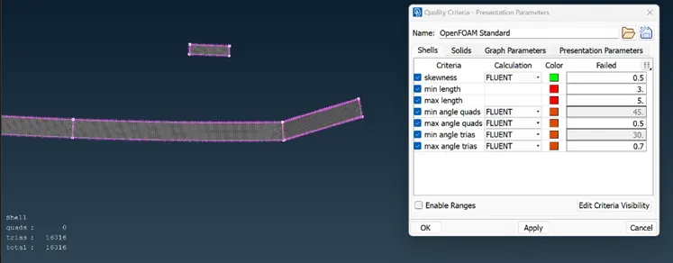
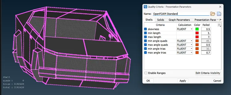
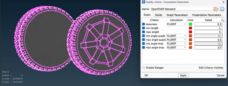
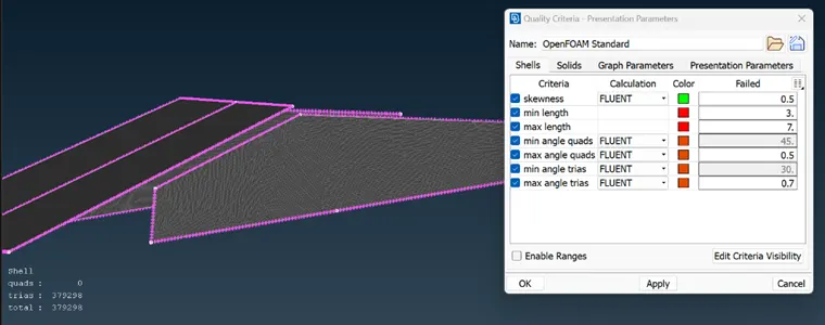
Fig 8. Quality criteria and mesh of PIDs
- Now as we finished the mesh lets move forward to create the wind tunnel and its mesh,
To create the wind tunnel there are some standards too which are given below;
Lets take X as length of car,
- Backside length of tunnel is 6x+distance from center to back of car which is,
6(5740)+3230 = 37670mm
- Front side length of tunnel is 4x+dist from center to front of car which is ,
4(5740)+2530 = 25490mm
- Bottom surface of tunnel is dist from car body base to base of tire, which is 380mm
- Both sides are at X distance which are 5740mm
- Above given are the dimensions of wind tunnel, now we start from bottom surface in which first we go to point section in which we select relative point option in which we click on center of car base and then give dimension 380 at -Z direction. Likewise for left and right we give direction at x and -x direction respectively and for backside and front side we give dimension at y and -y direction then we join those points using curve create option.
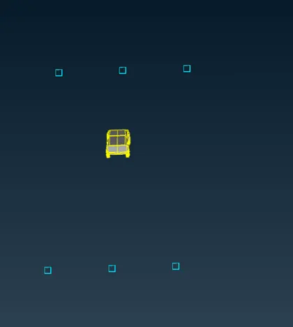
Fig 9. Points created around car body for wind tunnel
- Now using create new face option we select those curves and create the surface, then we create the offset of that surface at distance of 18750mm. now as we got the top and bottom surface lets create other surfaces by selecting cons and then delete those curves and points. And simultaneously we assign the PIDs for that surfaces too.
- Next we move forward to create the mesh of that surface so first we create the mesh for bottom surface of 50mm target length and like wise 150mm for top surface as our mostly focused area is near car and around bottom surface. Now to create a mesh based on this criteria we use spacing option for all the sides of tunnel and set minimum value as 50 and max limit till 150 and create the mesh there.
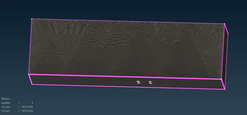
Fig 10. Surface mesh of wind tunnel
Learning outcomes:
We get to learn the things like how to choose the target length of mesh for different parts according to their application also we learn how to clear the complex geometry parts.
Results:
As a result we get the cleared geometry with 0 off mesh on it which means perfectly falling in quality criteria, also we create the wind tunnel with varying mesh with more fine mesh on most focused parts of geometry. And also we are successful at creating the one body volume across the car which we can see below in image;
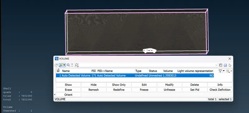
Fig 11. Volume define
link of geometry is given below:
https://drive.google.com/file/d/1W_ewWVsEXbuyN9ZlVjYXqLPoLALJ12Qu/view?usp=sharing
all quality criteria are uploaded on portal
Conclusion:
In the end we conclude that we successfully cleaned the geometry and create the mesh too which fully falling in quality criteria too.