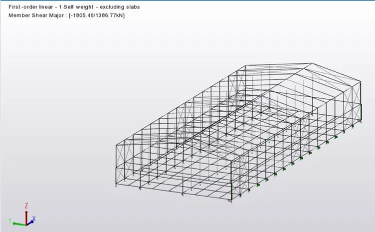
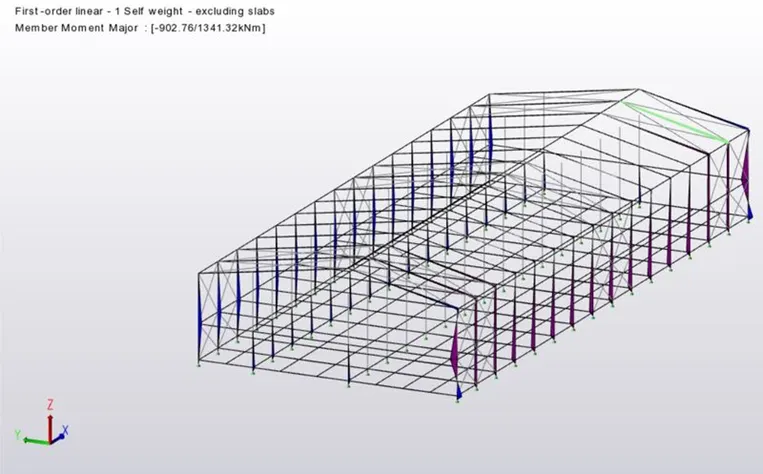
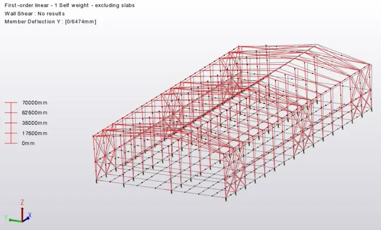
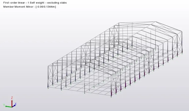
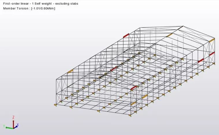
Project 1_Analyze and design a steel building to 10T CRANE as per IS standard code using TEKLA STRUCTURAL DESIGNER.
Que :- Analyze and design a steel building to 10T CRANE as per IS standard code in TEKLA STRUCTURAL DESIGNER. Refer the
attached plan and
elevation. Provide bracings and moment connection for lateral stability.
Consider dead, live, equipment and wind loading. Consider the brick wall loading for 150mm thick and 1.5 KN per sq m for wall
and roof
cladding.
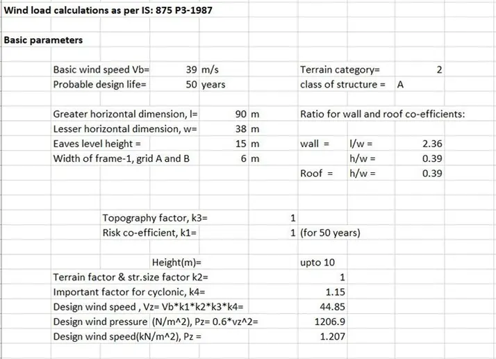
Assume wind loading basic speed as 39m/s
Report of each member to be generated and extract drawings of structural plans from the software
Ans :-
Aim : To Analyze A Building To 10T Crane Load. Create a structure As Per The Given Plan In The attachments Provided.
Tools Used :-
- Grids.
- levels.
- File.
- Model.
- Manage property sets.
- Column.
- Beams.
- Frames.
- Loads.
- Loadcases.
- Wall Panels.
- Roof Panels.
- Analyze.
Procedure :-
1. First Open A New File To Start the structure as per The plan Given In the Attachments.
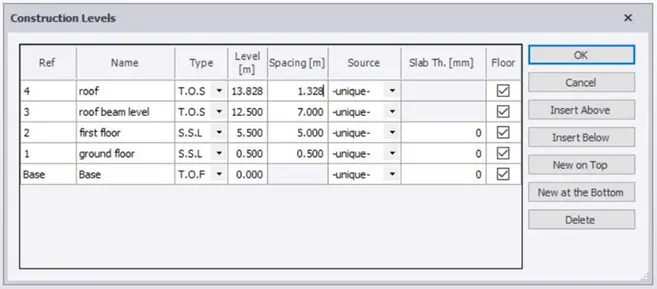
2. Click on Construction levels And Add All The Levels As Per The Cross section Plan Given.
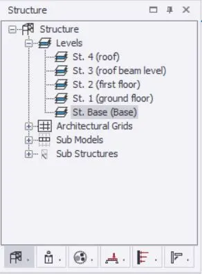

3. Select Grides Tool And Draw A Horizontal Grid Lines
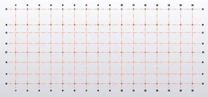
4. With The Option Parallel Quick Draw The Remaning Grid Line
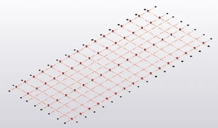
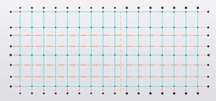
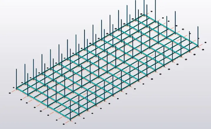
5. Repeat The Same Procedure For The Verticle Grid Lines also
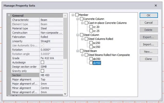
6. Now Click On Manage Property Sets Tool and Create Members Like Concrete Column , Steel Column And Steel Beams Of
Different grades
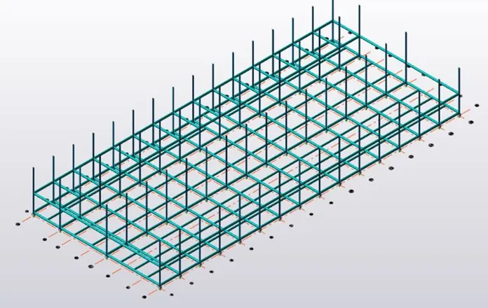
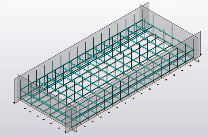
7. Now Construct Concrete Column Where Ever Necessary
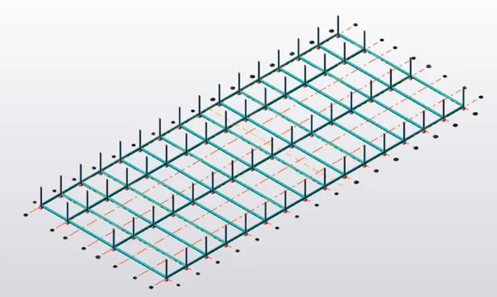
8. Next On The Concrete Column Construct Steel Columns and Join The Using Primary Beams.
9. To Give Extra Strength And support To The Structure Provide Secondary Beams.
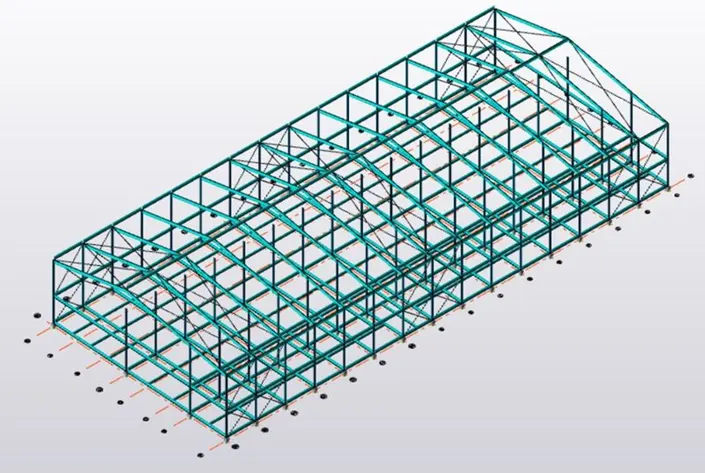
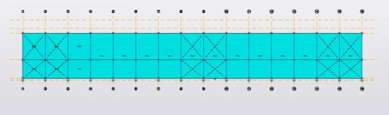
10. Next Select the frame Tool and create Frame Which Will Be Helful To Do The Remaining Work
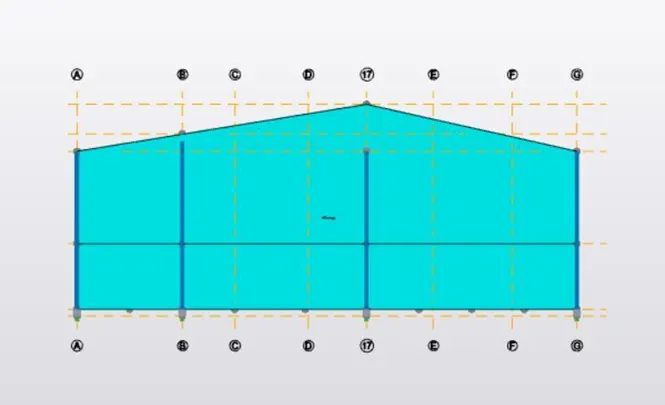
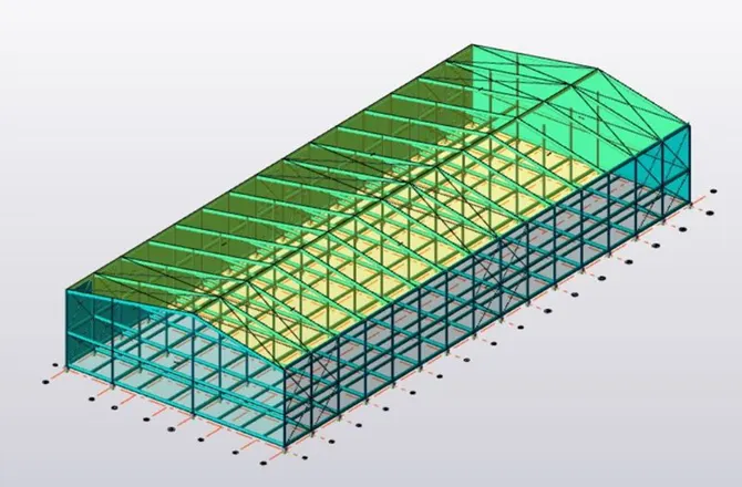
11. Validate The Model To check weather There Are Any Errors
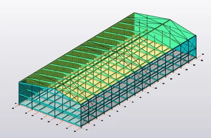
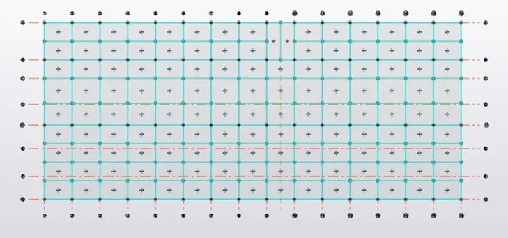
12. Now On selecting The particular Frame Construct The rafter And The Roof Using High Grade Steel bars
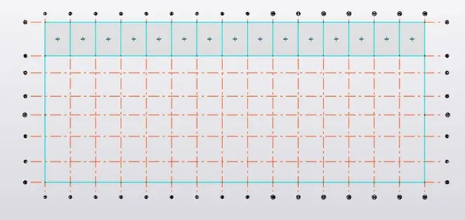
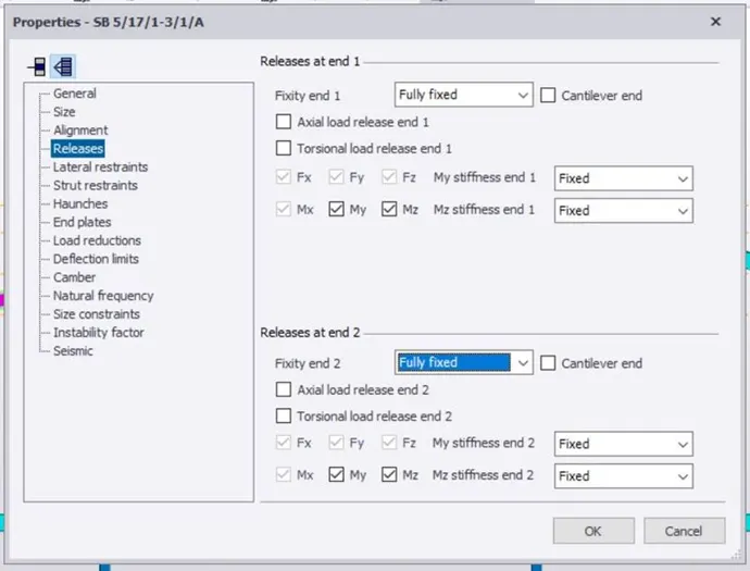
13. After Construction Of The Roof Convert The Beams To fully Fixed Support
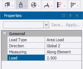
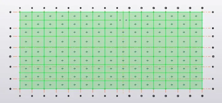
14. Now With The Helps Of X Braces Tool Construct X Braces On Both Sides Of The Structure And Well As On The Roof
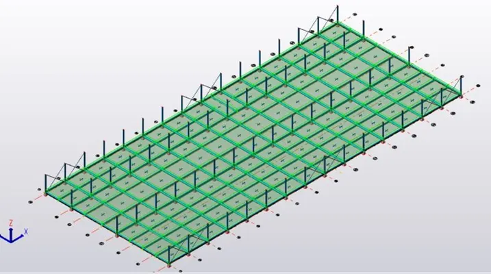
15. Now create wall and Roof Panels To The structure On All Sides
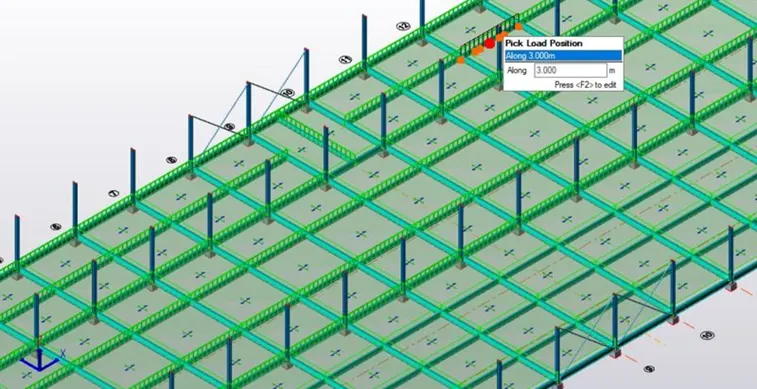
16. Perfrom The Crane Loading Calculatios
Crane Load Calculations :-
Max Wheel Load
Maximum Concentrared Load On Crane = 100 + 35 = 135 KN
Self - Weight Of Crane Will Act As Uniformly Distributed Load Of Intensity
= 160/20 = 8 KN/m.
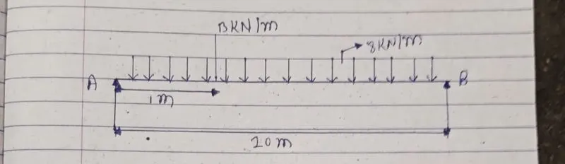
Taking Moment About A :
Ra X 20 - ( 135 ) X ( 19 -8 ) X ( 20 X 10 ) = 0
20Ra = 297000
Ra = 208.25 KN
Taking Moment About B :
Rb X 20 - ( 135 ) X ( 1 -8 ) X ( 20 X 10 ) = 0
20Rb = 189000
Rb = 86.75 Kn.
Ra + Rb = 100 KN.
The Reaction from The Crane Girder Is Distributed Equally On Two Wheels At The End Of The Crane Girder.
Maximum Wheel Load On each Of The Crane Wheel = 208.25/2 = 104.125 KN.
Maximum Bending Moment :-
Assume Self - Weight Of The Gantry Girder As 1.5 KN/m
Total Dead load = ( Self - Weight Of Rail + Self - Weight Of Gantry Girder ) 0.3 + 1.5 = 1.8 KN/m
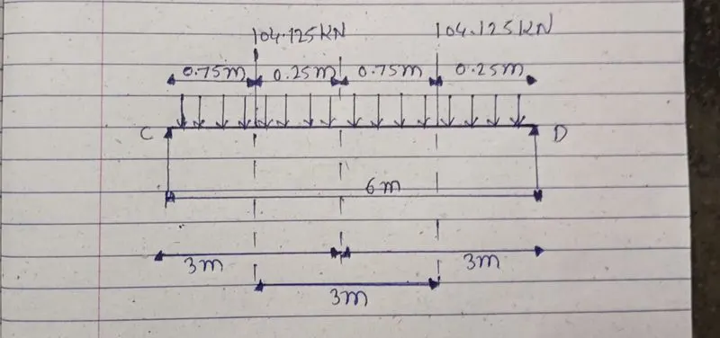
Taking moment About C :
Rc X 6 - 104.125 X ( 20.25 + 3 ) - 104.125 X 2.25 = 0
6Rc = 2655.187
Rc = 24655.187/6
Rc= 130.15 KN.
Taking Moment About D.
Rd X 6 - 104.125 X ( 0.75 + 3 ) - 104.125 X 0.75 = 0
Rd X 6 = 468.56
Rd = 468.56/6
Rd = 78.06 KN.
Bending moment Under wheel Due To Live Load = Rd X 2
= 78.09 X 2
= 156.18 KNm
Bending Moment due to Impact = 0.10 X 156.18 ( 10 % Increase Due To MOT )
= 15.618 KNm
Total Bending due To Dead Load = W X 1 X 1/2
= 1.8 X 6 X 6/2 = 8.1 KNm
Maximum Bending Moment = 171.798 + 8.1
= 179.89 KNm.
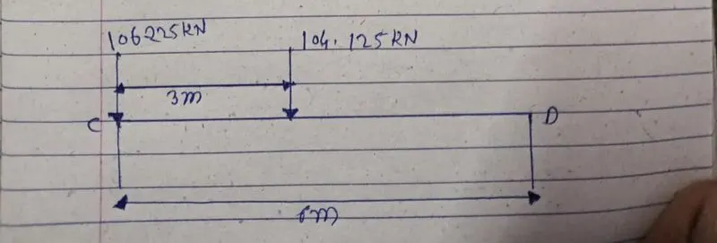
Maximum Shear force :-
For Maximum shear Force, One Og
Rc X 6 - 104.125 X 6 - 104.125 X 3 = 0
Rc = 937.125/6
Rc = 156.18 KN
The maximum shear Force Due To wheel Load = 156.18 KN
Lateral Forces :-
Lateral forces tranverse To Rails = 5% Of The weight Of Crab And Weight Lifted
= 0.05 ( 135 )
= 6.75 KN
Lateral forces On Each Side Wheel F1 = 6.75/2 = 3.375 KN
Maximum Horizontal Reaction Due To The Lateral Force By Proportion At C
= Lateral Force X Reaction at C Due To Vertical Load/ Maximum wheel Load due To Vertical Load
= 3.375 X ( 130.15/104.125 ) = 4.21 KN
At D
= Lateral Force X reaction At D Due To Vertical Load / Maximum Wheel Load due To Vertical Load
= 3.375 X ( 78.09/104.125 ) = 2.53 KN
4.21 + 2.54 = 6.74 KN
Bending moment Due To Lateral Load By Proportion
3.375 X ( 15.18/104.125 )
= 5.06 KN/m
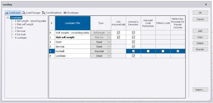
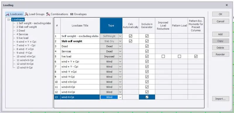
17. Now click On Loads And Crate New Loads Like dead And Live Loads.
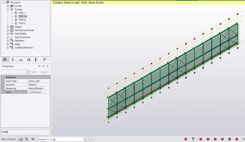
18. Create Slab To The Structure By Clicking On Slab On Beam Option
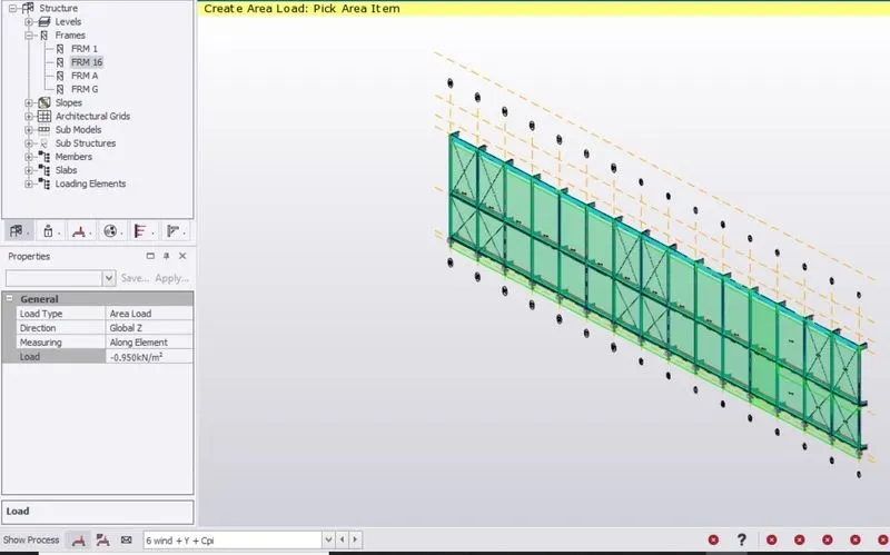
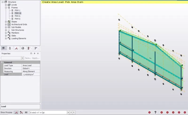
19. Now Place Live And Dead Load On The structure As Per IS Standard Codes
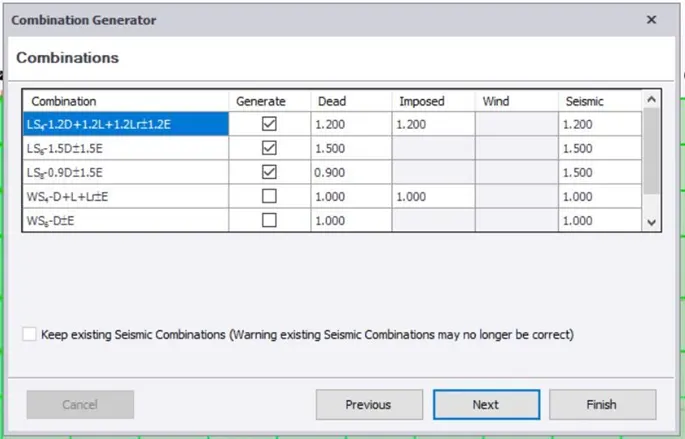
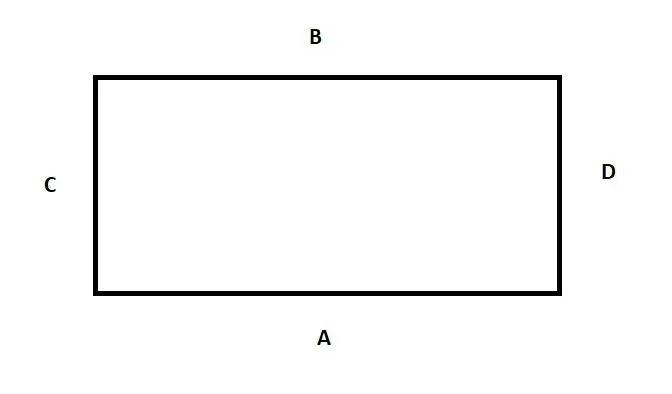
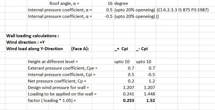
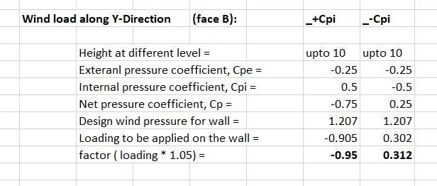
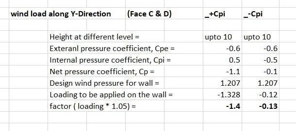
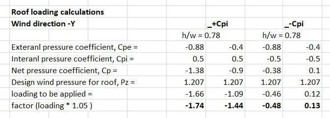
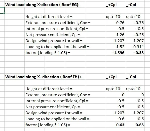
20. Now Create New wind Loads with Both + cpi And - cpi Values

21. At Last add seismic Load To The Structure
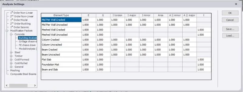
22. Analyze The structure And Do Necessary Change To Correct The Errors
Result :-
With The Above Steps we Can Construct A Steel Structure And Add Different Kinds Of Loads And analyze The Structure