Pre-processing of an IP substrate component using ANSA
AIM
The objective of this tool test is to perform a mid surface extraction of the component and successfully create a finite element model of it and furthermore refining the mesh such that it validates every quality criteria set.
Tool tests are usually required to be completed within a given period. Hence timing the duration to complete each component respectively is recommended.
INTRODUCTION
An Instrument Panel (IP) substrate is a plastic component in an automobile made up of ABS/polycarbonate alloys. Thy is fabricated using the method of plastic injection molding where a single component with a closed volume acts as the mold within which the hot molten metal is poured and then baked.
In an automobile, these plastics allow for complex designs in items such as airbag housings, center stacks for instrument panels, and large, integrated instrument panel pieces.
Such IP substrates made of such polymers are widely preferred in automobiles and in certain other applications as they result in a seamless instrument panel with greatly reduced NVH levels, molded-in color and with significant cost savings for the manufacturer.
Fig 1: IP Substrate
Modeling an IP Substrate
Since these components are very thin by nature, they can be easily modeled as a shell component during the pre-processing stages. Meaning, this component has dimensions along its length and breadth which are incomparable to the thickness of the component. In other words, the thickness of an IP substrate is negligible compared to the other two dimensions, hence during pre-processing the mid-surface of the component can be extracted.
Moreover, since this component is formed using mold technique and has a closed volume, these can be relatively easy to be mid-surfaced using automatic procedures provided the thickness is constant throughout it's length.
PROCEDURE
1. Geometry Cleanup
Initially, every model has to be checked for geometrical errors. Prior to this, it is best practice to perform a topology clear up to make sure that continuity is maintained between every cons and that it doesn't display double cons as single cons.
ANSA can give a layout of all the geometrical error from our component model.
To perform geometric checks, Checks - Geometry - Select required params
ANSA is also capable of clearing small geometrical errors if it's within its capability and based on memory allocated for it.
In our case, ANSA was able to stich many crack edges and clear triple cons at unrequired areas. However it failed to clear certain unchecked faces due to improper alignment and stitching of cons (as shown below)
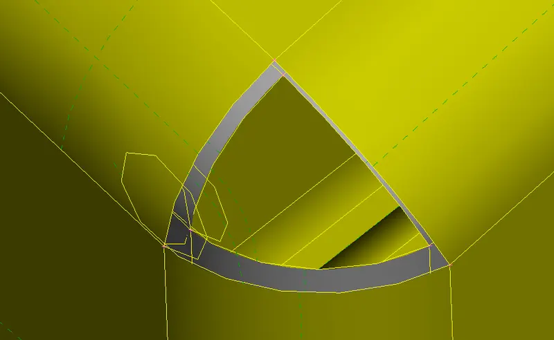
Fig 2: Geometrical error
These can be eliminated by deleting the faces and the improperly oriented cons and creating a new face using the faces - new option.
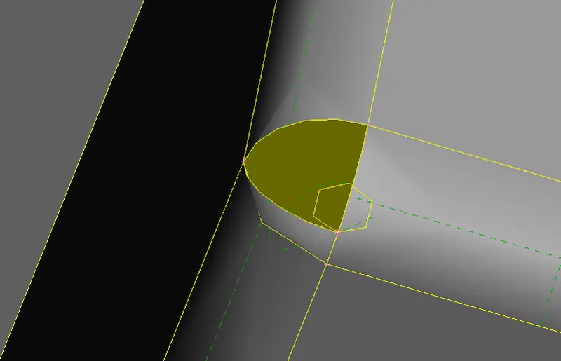
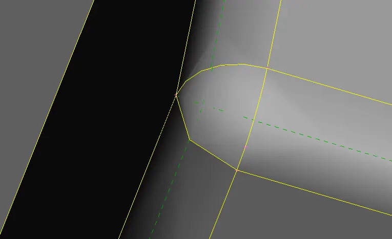
Fig 3: Unchecked faces (cracked) Fig 4: Cleared cracked faces
Finally all such areas are stictched and every geometrical errors are cleared.
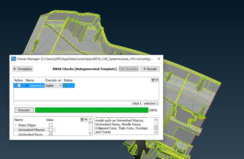
Fig 5: Geometry checks manager
NOTE: The single con at the edge of the component can be ignored as these cons don't share a common edge or two faces. However, for the process of auto mid-surface extraction the component has to be a closed volume. Although the above component dosent have the adjacent component to which it has to be attached to like the dashboard, for our case we can model it as a closed volume so auto mid feature will work.
This would further cause more geometry and topo cleanup and the final geometry check has been performed by checking on the single cons and the entire geometry has be cleaned (as shown below)
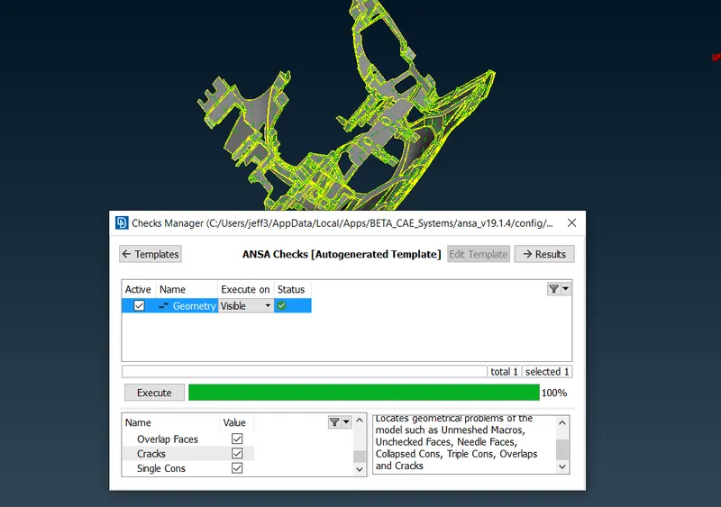
Fig 6: Geom checks manager
2. Mid surface extraction
Mid surface extraction depends on the symmetry and thickness of each respective part in a component. In case of varying thickness, the auto mid surface doesn't give a proper result. Hence manual mid surface extraction using the offset and manual mid features can be implemented.
The offset command can be used for known thickness features in the component where discontinuity occurs due to other mid features present. Whereas the single/multi middle feature can be used for features that are symmetric and are separate from the rest of the component (i.e no discontinuity)
While extracting the mid of the model manually it is recommended to follow along a single direction. It is not recommended to generate the mid at random regions in the model rather follow a specific pattern and direction to achieve it.
- Use the middle -> single feature on areas which are symmetrical like ribs.
- Measure the thickness of each element for offset since the thickness of the rib components vary to the entire model
- Extract mid from the side of the component where the details are present. Offseting a plain side would be a redundant to the actual model and its required features.
- Ocassionally orient the model using the orient -> select command
- Use the faces -> new command to cover areas that are vacant post to an extraction
- Use the intersect feature to trim out the entities that cross beyond the surface of the model
- Use extend to extend the faces/cons of the target entity onto the surface.
- To capture small features that are oriented parallel to the surface face, they can be modeled as thin strips by creating curves capturing the perimeter of the feature and then project it to the face and then create a new face.
Finally the model is completely extracted for its mid surface (as shown below)
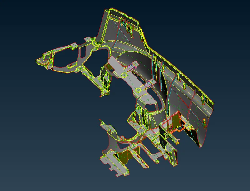
Fig 7: Mid-surfaced part
Finally the topology of the model is optimised by performing another topo cleanup followed by assigned a PID for the entire component.
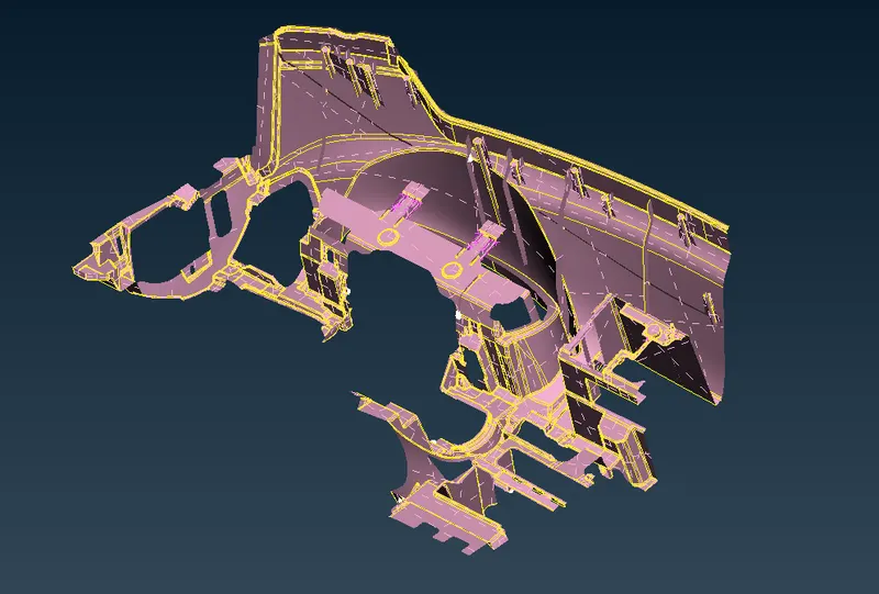
Fig 8: Assigned PID
3. MESHING
Finally the model is meshed using the given mesh parameters with an average length of 4. The best mesh method is used in this case. However to get a more accurate mesh result spot mesh can be implemented after the complex model is discretized into specific compartments using cons.
Then the mesh is refined using various ansa in-built tools like reconstruct, smooth, improve and using small commands like split, join etc.
We finally get the below mesh result
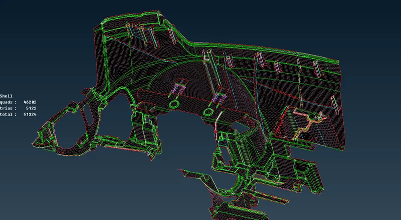
Fig: 9 Meshed model
The model was sucessfully meshed with less than 9% of trias which were generated using the mixed mesh option.
The model can then also be view as a solid model using the PID assigned to it where the original thickness of the model is specified. To view the shell as a solid model we can visualize it from the presentation parameters tab in the mesh criteria box (as shown below)
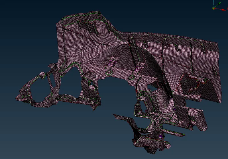
Fig 10: Shells as solids
CONCLUSION
Hence the given model was extracted for mid-surface and successfully meshed. It was then refined so that the elements pass for the given quality criteria.
The mid-surface extraction of the entire model (manually) took about 2hrs 13mins and the mesh generation and refinement was completed within a hour.
LEARNING OUTCOMES
Gained knowledge on,
1. Extracting mid-surface manually for an intricate and complex geometry
2. Various tools to extract mid-surface and correct errors
3. Shell meshing using both best and spot mesh generation method
4. Mesh refinement using different built in features.