Project 1
Aim of Project-
Design and Develop a PWM controlled fan load with DC motor
Theory-
This paper presents the work for the design of the fan speed control system using Pulse Width Modulation by establishing a connection between an H bridge circuit and a Dc motor. A fan-type load equation has been used to analyze the output results instead of a physical model of a fan in Simulink. The fan speed is varied according to the input voltage using the PWM technique.
By changing or modulating the timing of these pulses the speed of the motor can be controlled. A stepwise change in the speed variation is given and the full load speed is observed. In this model, all input ports of the H-Bridge block except the PWM port are connected to the ground. As a result, the H-Bridge block behaves as follows:
- When the motor is on, the H-Bridge block connects the motor terminals to the power supply.
- When the motor is off, the H-Bridge block acts as a freewheeling diode to maintain the motor current.
We have drive a fan load by DC motor with PWM.
>Pulse Width Modulation
Pulse Width Modulation, or PWM, is a technique for getting analog results with digital means. Digital control creates a square wave, a signal switched between on and off. This on-off pattern can simulate voltages in between full-on and off by changing the portion of the time the signal spends on versus the time that the signal spends the duration of "on time" is called the pulse width. To get varying analog values, we change or modulate, that pulse width.
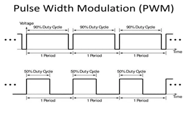
Figure 1:PWM modulation
>Load characteristics
The torque speed curve of a load is a plot showing its torque requirement on the y-axis versus the speed on the x-axis. It’s the torque requirement of the load from zero speed to full speed. It is application/load specific and varies with different load types. Loads like centrifugal pumps and fans follow the quadratic speed torque curve, where torque varies square times. These are also called constant torque loads or applications.
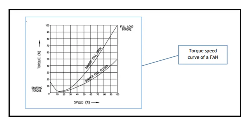
Figure 2:Torque-Speed characteristics of FAN
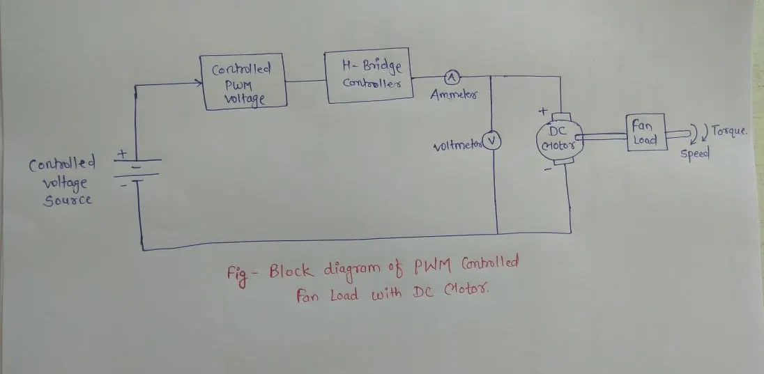
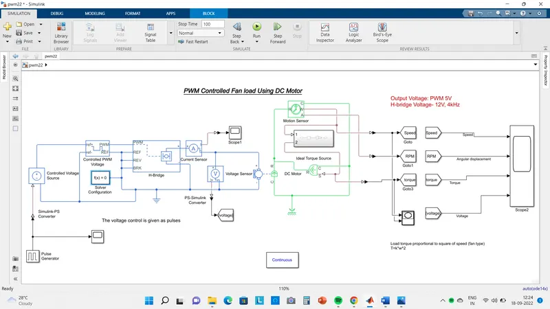
Following block diagram shows the different component of the project.
Components are,
1. DC controlled voltage source
2. Controlled PWM voltage
3. H- bridge controller
4. DC motor
5. Fan Load
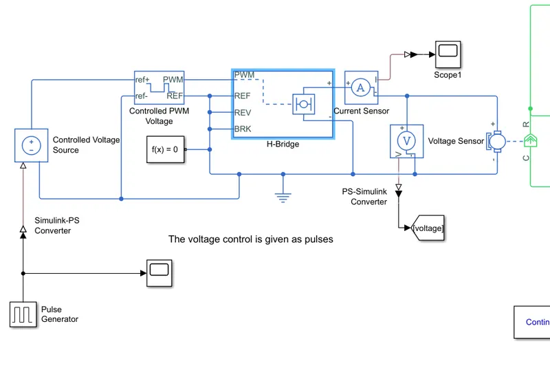
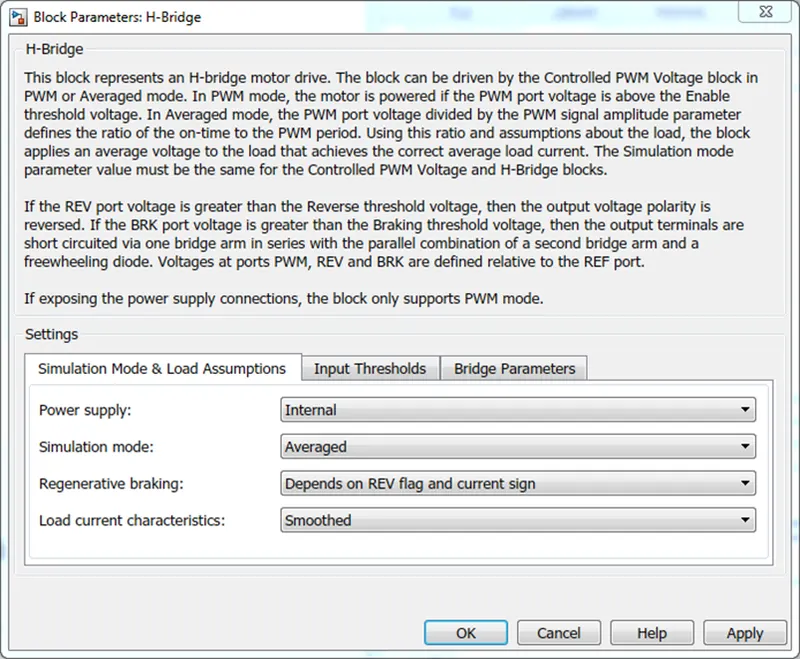
By feeding the voltage of conrolled voltage source by pulse generator to the PWM controller it can modify the reference voltage as per pulse generator input. this input is given to H-bridge converter block can be driven by the Controlled PWM Voltage block in PWM or Averaged mode. By this controlled supply current & voltage drive the DC motor & DC motor coupled with fan load. We measure the speed & torque draw it on xy-graph also measure current & voltage & angular displacement see the combine wavaforms in scope.
Method-
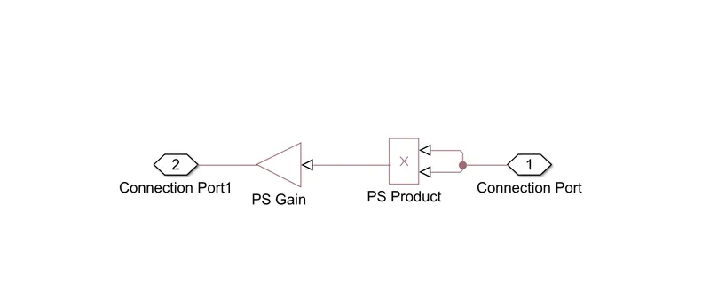
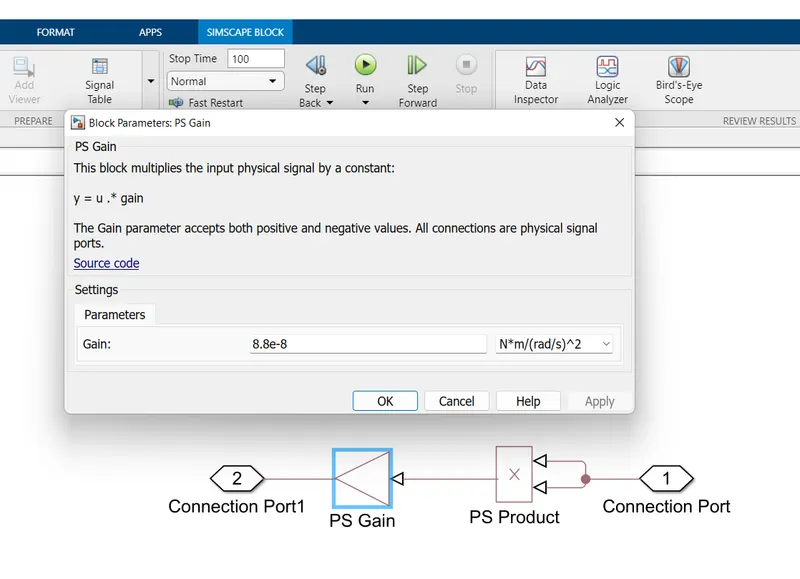
Torque exerted by fan load TL`directly proportional`w^2
TL = c w^2
based on c we can designe a fan load set voltage and current.
1. Power and Motor Controlled System:-
1.1 H-Bridge:-
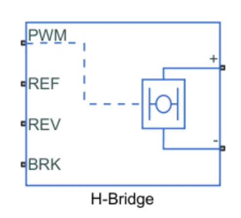
The H-Bridge helps in controlling the power that is input according to the requirement. The output provided is converted voltage as per the controlled parameters.
1.2 D.C Motor:-
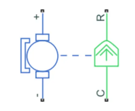
This is the DC Motor which would give rotational power to the fan and become the sole power generation source.
The DC Motors terminals are connected as mentioned below.
+ =Electrical signal to the motor Positive Terminal
- =Electrical signal to the motor Negative Terminal
R=Casing of the Motor connected with the Mechanical Rotational Reference Block
C=Rotor Case connected to the Mechanical Rotational reference
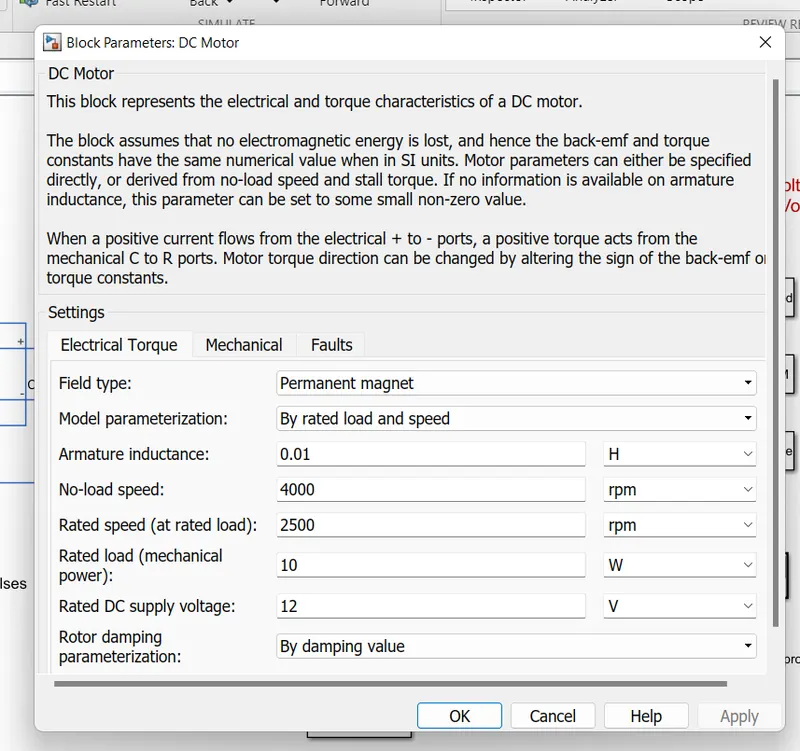
The parameter considered is, The Armature inductance is as default, varied the changes in the No-Load Speed 4000 rpm, the rated speed 2500 rpm, the Rated Load at 10W, and the Rated DC Supply Voltage 12 V. All other parameters are as default.
1.3 Controlled PWM Voltage:
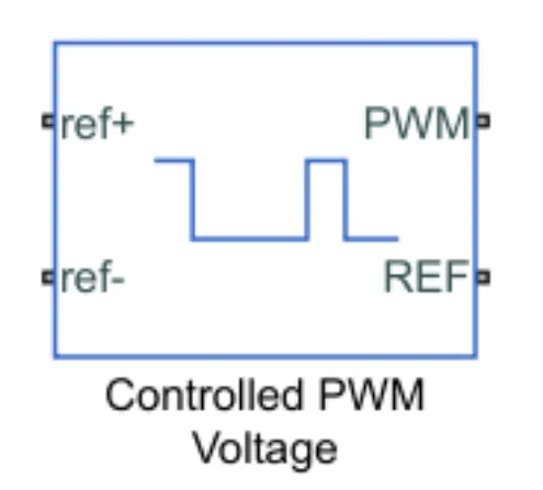
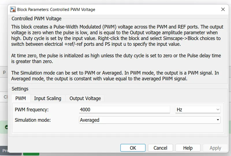
The Controlled PWM Voltage Block helps in keeping the Modulated Pulses as per the required pulses. So that the operations happen smooth and higher variations are not observed.
The Ports are connected as follows.
PWM=PWM connected directly to the H-Block
REF=REF connected directly to the H-Block
ref+ = Reference Positive connected with Driver Model ith the Acceleration Commands from the
ref- =Reference Negative connected with the Deceleration Commands from the Driver Model
Note: The parameters are set as default.
2. Mechanical Load
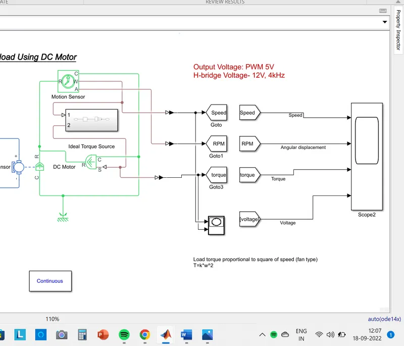
2.1 Fan Subsystem
2.2 Ideal Motion sensor
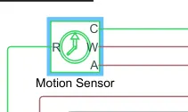
This block measures angular velocity or angle in a mechanical rotational network. The sensor is ideal since it does not account for inertia, friction, delays, energy consumption, and so on.
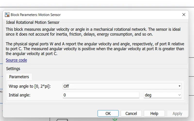
The physical signal ports W and A report the angular velocity and angle, respectively, of port R relative to port C. The measured angular velocity is positive when the angular velocity at port R is greater than the angular velocity at port C.
2.3 ideal Torque Source
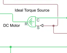
The block represents an ideal source of torque that generates torque at its terminals proportional to the input physical signal. The source is ideal in a sense that it is assumed to be powerful enough to maintain specified torque regardless of the angular velocity at source terminals.
Block connections R and C are mechanical rotational conserving ports. Port S is a physical signal port, through which control signal that drives the source is applied. Positive signal at port S generates torque acting from C to R.
3. Controlled Voltage Source
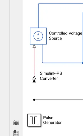
The block represents an ideal voltage source that is powerful enough to maintain the specified voltage at its output regardless of the current passing through it. The output voltage is V = Vs, where Vs is the numerical value presented at the physical signal port.
4. Pulse Generator
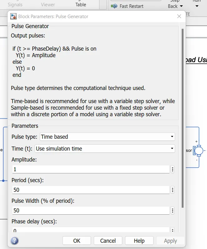
5. Solver configuration
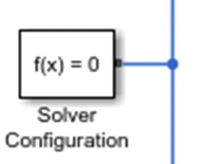
A Solver Configuration is added to ensure proper solving of the mathematical equations by the model.
Whole Simulink Model
Observation from the Result-
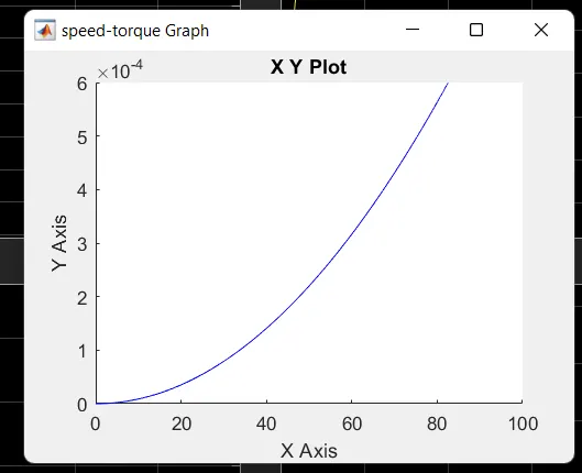
This xy-graph is the speed torque graph shows that Load torque proportional to square of speed (fan type)
T=k*w^2
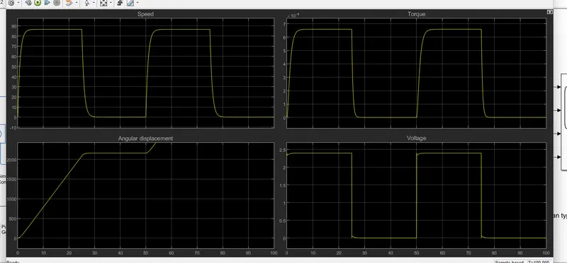
from the scope block sees that voltage is change with respect to pulse duty ratio by this speed is increases & in square proportion torque increases. The angular displacement also increase in step see in the scope waveform.
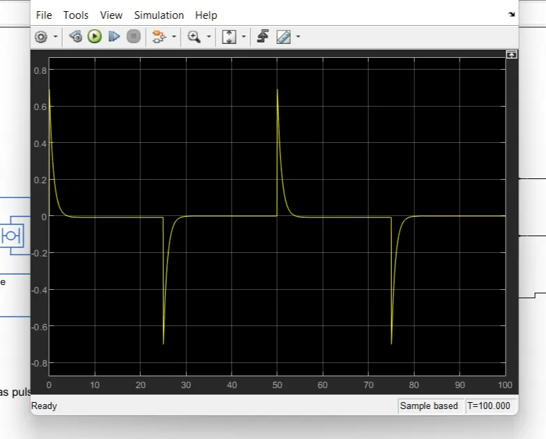
Current waveform
Conclusion-
From the above model and from the assumed parameters we found that the speed, Torque & angular displacement of an fan is shown in scope waveform matches with desired response. A PWM-controlled DC motor using an H bridge circuit was modeled in Simulink and results were analyzed. The output plots justified the theory discussed. The load torque characteristics of a fan is obtained. The full speed was observed for a full voltage of 12V from the DC motor.