Project 1
PWM controlled fan load with DC motor
Objective;
To Model a fan type load in simulink and to control its speed by using the PWM Method
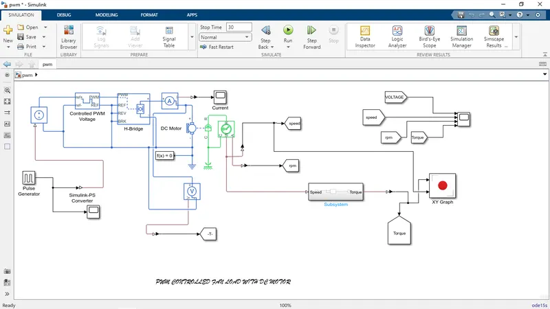
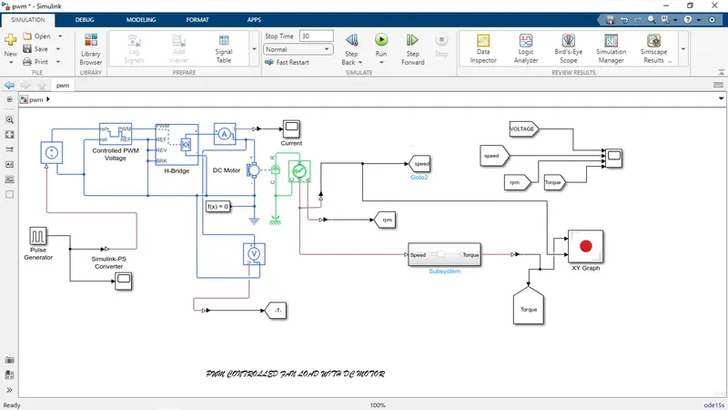
- This works to model a DC motor driven by an input signal that approximates a pulse-width modulated signal
- these signals are fed to the motor using an H bridge circuit
- We assume that the change of operating speed of the fan is through stepwise modulation through a fan regulator
- PWM, H bridge, DC Motor
BLOCKS ARE USED IN MODEL:
- Pulse Generator
- Controlled PWM Voltage
- H-Bridge
- DC Motor
- From tag
- Scope
- Subsystem
- XY graph
- Solver
SIMULATION MODEL;
SCOPE (OUTPUT);
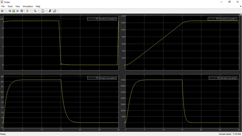
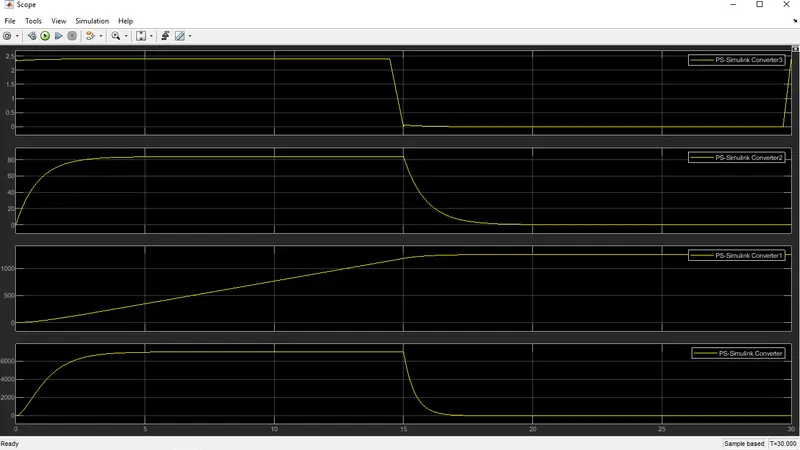
- The speed of the fan is varied according to the input voltage using PWM technique.
- By changing or modulating the timing of these pulses the speed of the motor can be controlled.
- When the motor is on, the H-Bridge block connects the motor terminals to the power supply.
- When the motor is off, the H-Bridge block acts as a freewheeling diode to maintain the motor current.
Pulse width Modulation;
- Pulse width Modulation (PWM) is a method of reducing the average power delivered by an electrical signal,by effeciency it into discrete parts
- The average value of voltage (and current) fed to the load is controlled by turning the switch between supply and load on and off at a fast rate.
Model Description;
- The DC motor block uses manufactuer datasheet parameter,which specify the motor as delivering 10w mechanical power at 2500rpm and no load speed as 4000rpm when run from a 12v dc supply
- H bridge block represents a motor drive.
COMPONENT USED IN MODEL;
PULSE GENERATOR;
- Pulse type determine the Computational technique used
- TIme-based is recommended for use with a variable step solver,while sample -based is recommended for for use with a fixed step solver or within a dicrete portion of a model using a variable step solver
IDEAL ROTATIONAL MOTION SENSOR;
- This block measure angular velocity or angle in mechanical rotational network
- the sensor is ideal since it does not for inertia,friction,delays,energy consumption.
DC MOTOR;
- The block assumes that no electromagnetic energy is lost ,and hence the back-emf and torque constants have the same numerical value when in SI units
- parameter can be set to some small non-zero value