Project 1
Input parameters given in the problem statement are
Stator resistance = 0.531 ohm
Rotor resistance = 0.408 ohm
Stator and rotor inductance = 2.52mH
Mutual inductance = 84.7mH
Inertia = 0.1kgm2
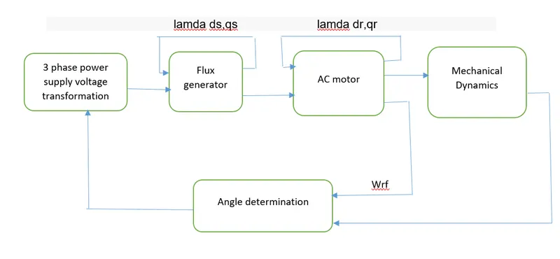
The modelling will be done as per the block diagram shown above. The three phase supply given to the power supply voltage transformation will be converted to dq supplt. The dq supply is then fed to the flux generator. The flux will be generated which is having lamda dr and lamdaqr. The current from the flux generator will be fed to the rotor of te motor circuit and then the lamdaqr and lamdadr will be generated. These will power mechanical dynamics block and then torque and speed will be generated. Here the load torque is applied.
Voltage transformation in flux generator
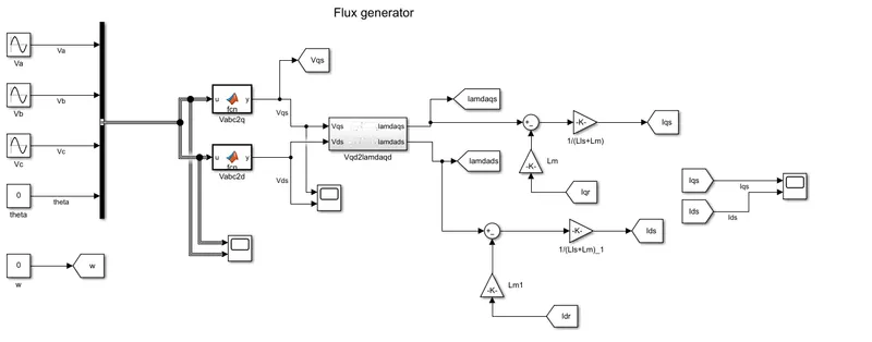
Three phase supply is given with the help of three sine block.The input supply was kept at 60Hz.
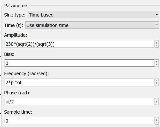
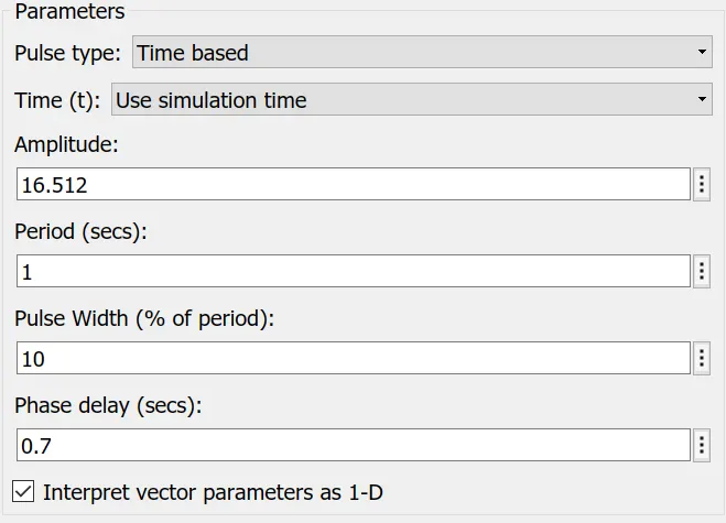
Paramters for Vb
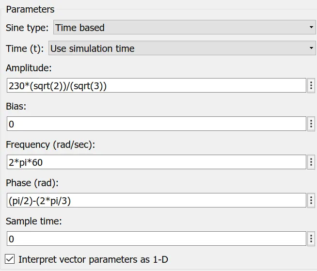
Parameters for Vc
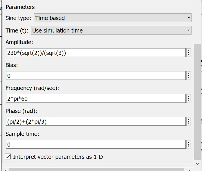
The inputs are being fed to bus creator and then the output is fed to matlab function block.
In the function block the value for the y is defined as
y = (2/3)*(u(1)*cos(u(4))+u(2)*cos(u(4)-(2*pi/3))+u(3)*cos(u(4)+(2*pi/3)))
y = (2/3)*(u(1)*sin(u(4))+u(2)*sin(u(4)-(2*pi/3))+u(3)*sin(u(4)+(2*pi/3)))
The output from the function block is Vds and Vqs.
This is then fed to the Vqd2lamdaqd subsystem.
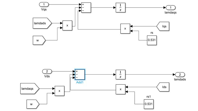
Here the modelling is done through feedbacking lamdaqs and lamdads.
Rotor speed is multiplied with lamdads and lamdaqs and subtracted with Vds and Vqs and Iqsrs and Idsrs.
Flux will be generated as lamdads and lamdaqs and then it is fed into the loop.
Induction Motor
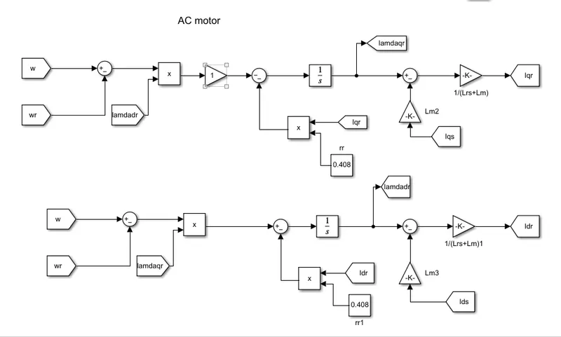
- Rotor speed and reference speed is compared at first.
- Then it is multipled with the flux components.
- The result is then subtracted with the Iqr component. The value for rr is provided in the problem statement.
- After integrating the result we get lamdadr and lamdaqr.
- Ids is multiplied with the mutual inductance whose value is already provided and the result is subtracted from lamda component.
- Iqs and Ids are obtained by adding a gain component whose value is(1/(Lrs+Lm).
Mechanical Dynamics
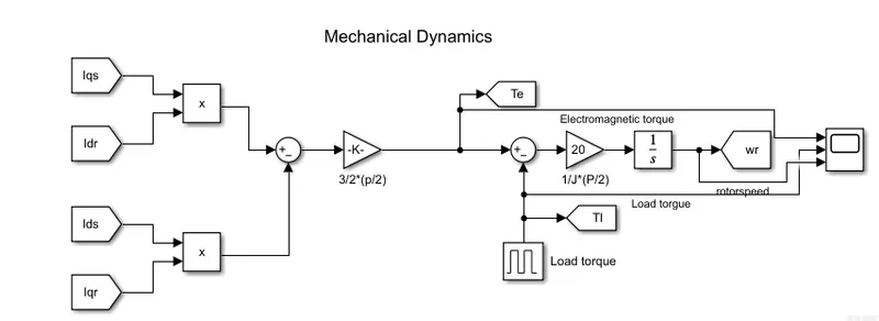
Here electrical components are converted to mechanical components.
- The electromechanical torque and reference speed is obtained.
- The difference of current components of Iq and Id components are subtracted and for torque gain is included to the result.
- Load torque is given in the form of pulses.
- In order to obtain speed the torque is multipled with (1/J)*p/2
In order to obtain the result of variables the components are fed to the scopes.
a) Simulate the start-up behaviour of the induction motor represented in the stationary d-q reference frame. Provide simulation plots of vqs(t),iqs(t),ids(t),iqr(t),idr(t),Te(t),Tl(t)andωr(t).">vqs(t),iqs(t),ids(t),iqr(t),idr(t),Te(t),Tl(t)andωr(t).
Here theta is given as zero
The outputs obtained are
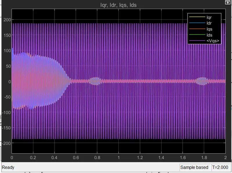
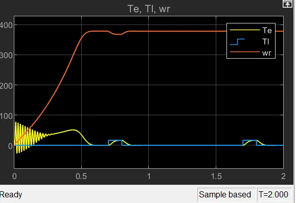
Here from the graph above we can observe that speed of the rotor increases . But when the torque increases there is a dip in the speed. During this time the current component increases, since torque and current are directly proportional.
b) Simulate the start-up behaviour of the induction motor represented in the synchronous reference frame. Provide simulation plots of vqse(t),iqse(t),iqre(t),Te(t),Tl(t)andωr(t).">veqs(t),ieqs(t),ieqr(t),Te(t),Tl(t)andωr(t).
The rotor rotates near synchronous speed
1800rpm = 188.5 rad/sec.
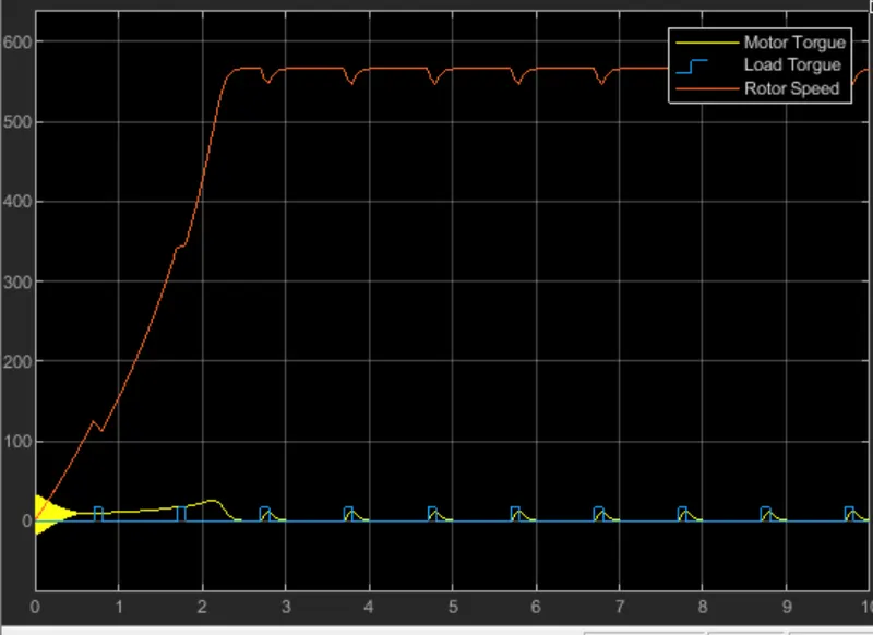
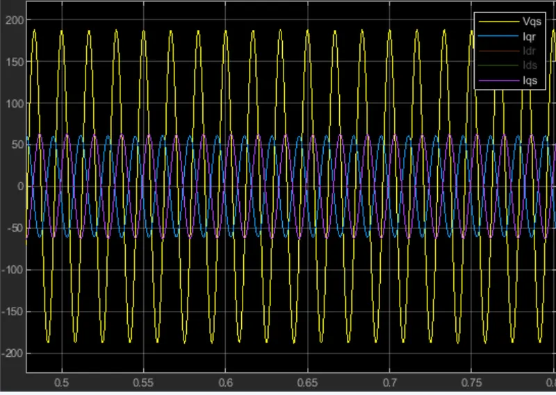
When the speed is increased to syncronous speed the rotor speed had almost doubled. But when the torque increases there is a corresponding decrease in the speed.
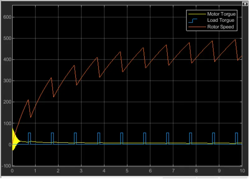
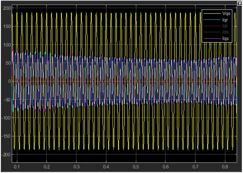
c) Simulate the start-up behaviour of the induction motor represented in the rotor reference frame. Provide simulation plots of vrqs(t),irqs(t),irqr(t),Te(t),Tl(t)andωr(t).
Now rotor speed is given as starting speed.
d) Simulate the start-up behaviour of the induction motor represented in the rotor flux reference frame. Provide simulation plots of vrfqs(t),irfqs(t),irfqr(t),Te(t),Tl(t)andωr(t)
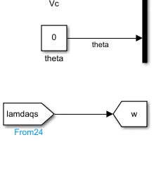
Now the flux is given as input speed
The waveform obtained is
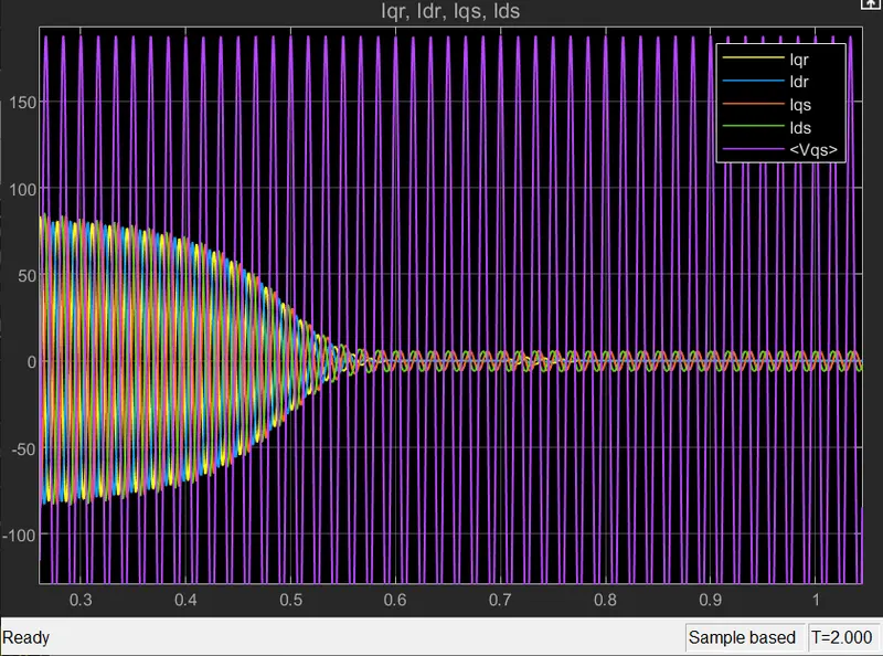
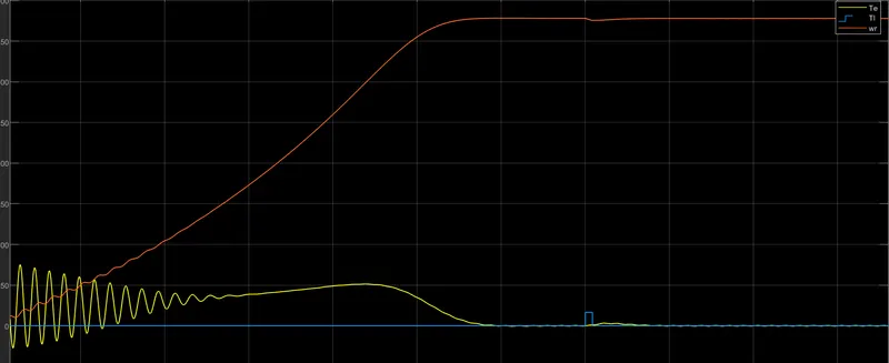
The response on the graph were similar to the other conditions, whenever the torque increase the speed decreases and there is a positive connection between torque and current.
CONCLUSION
Thus studied the output graph of the model for different conditions