Dash Board Sub Parts
Dash Board Sub Parts
Aim
- Open and check the geometry and perform geometry cleanup.
- Manual mid-surfacing of geometry using different techniques or by implementing various ways.
- Defining the quality criteria for the mesh generation.
- Meshing using best and batch or auto mesh, if prefferable, in ANSA.
- Assign individual surfaces its thickness.
- Clear all the joins from the mesh by keeping it as it is and release it from geometry.
- Convert shell mesh to solid mesh.
Objectives
- Open the dash boardmodel in ANSA and perform topology and assign proper orientation to the geometry.
- Perform geometry cleanup and create mid-surfacing of all the parts.
- Defeature all the connections of mid surfaces to generate proper mesh flow.
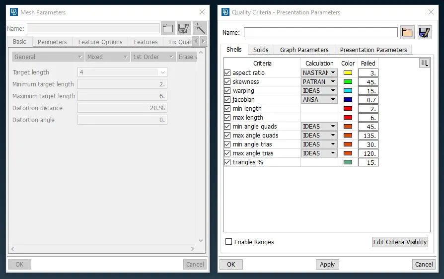
- Assign expected quality criteria in order to maintain mesh quality. Also provide average length of mesh elements with minimum and maximum length.
- Generate mesh using best and batch mesh command and reconstruct it to reduce number of tria elements. Then smooth it using smooth button.
- Give proper thickness to each mid-surface in element property section.
- check mesh if there any elements not fitting under our quality criteria and correct it using split and join element button.
- Clear all the joins from the geometry by keeping same element structure and release all the element from geometry.
- Finally, convert shell mesh to 2d solid meshto check thickness of each part and welding sections.
Import Model:-
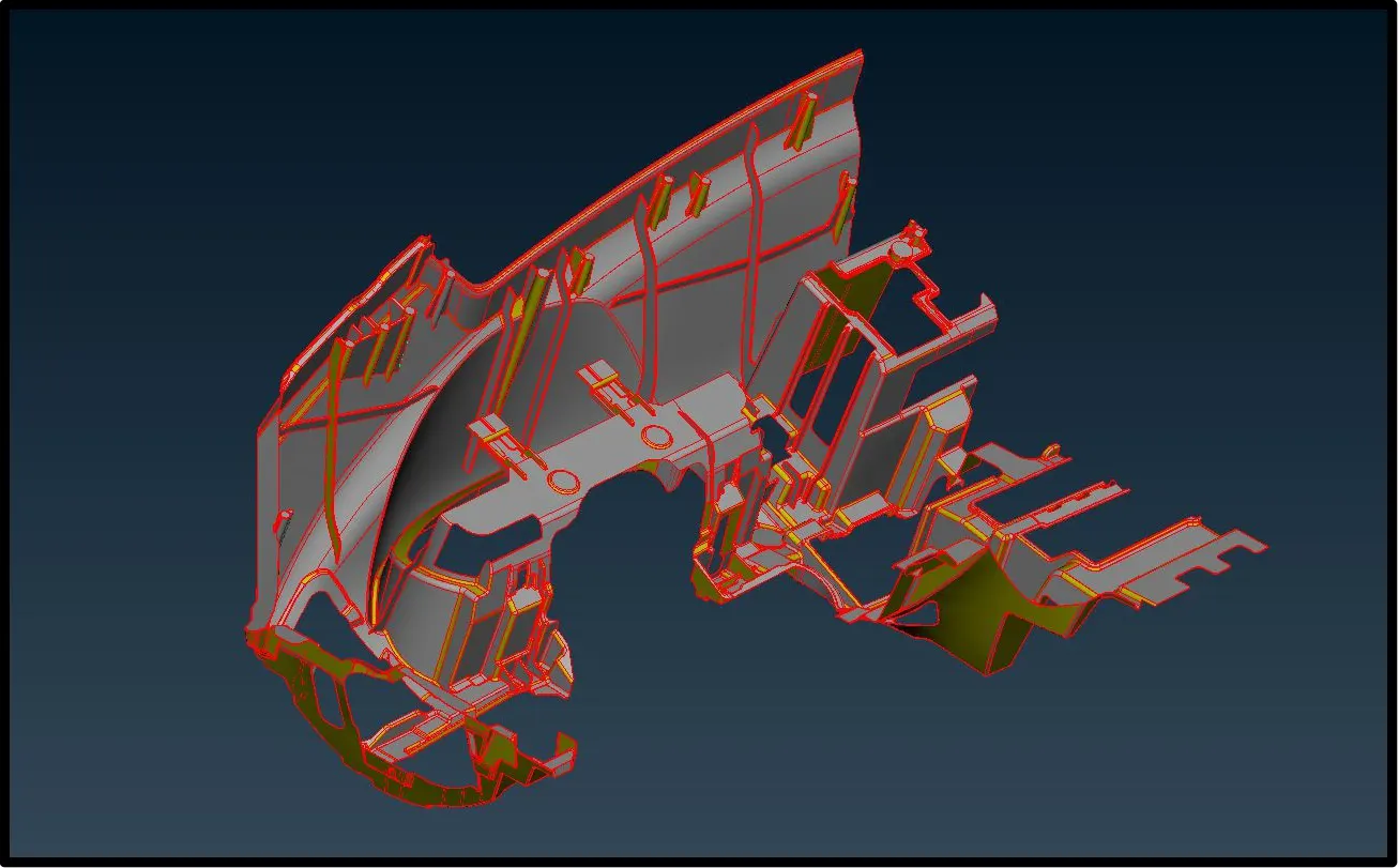
In this project our first step will be importing the .igs model in ANSA. We can do in by drag and drop method or using open option from file menu in ANSA. After, we open the model, it will look something like this.
Geometrical Topology:-
Firstly, Lets start with importing the geometry in ANSA using open button in file menu and perform topology to join all the faces as the file is in the igs format and faces are not connected to each other.
Orientation:-
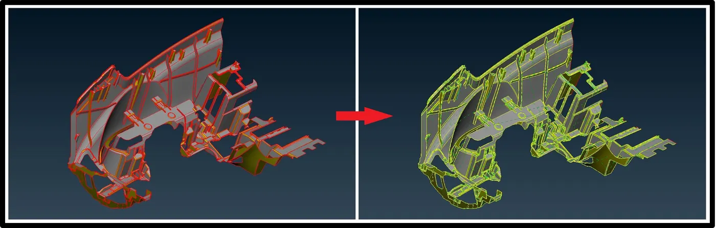
After topology, we can see some part of the geometry is of yellow colour and some are gray this mean geometry is not properly oriented so by using orient button in topo option we can orient it properly.
Geometry cleanup:-
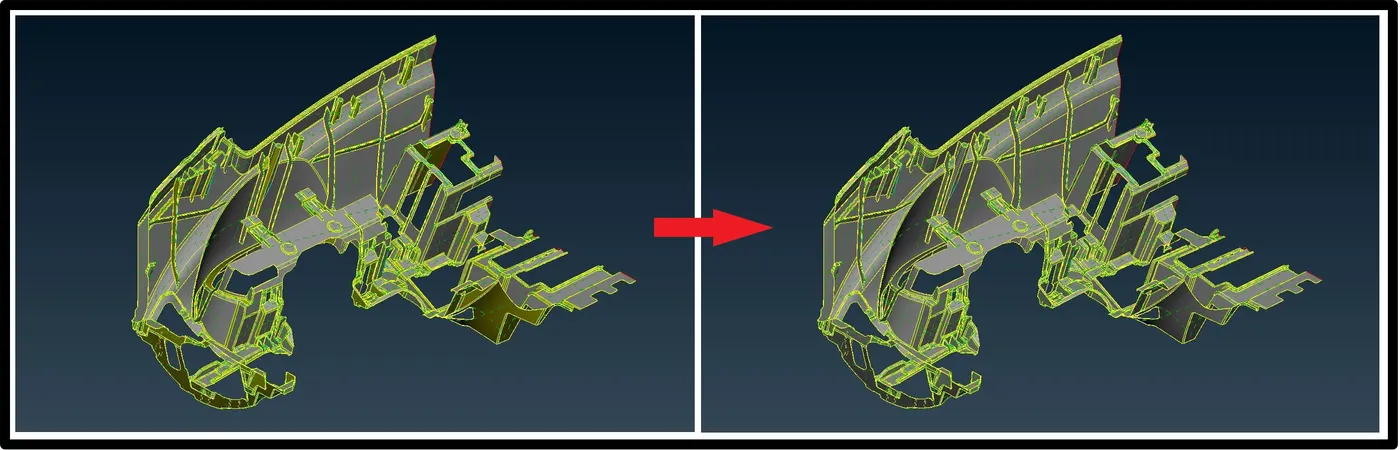
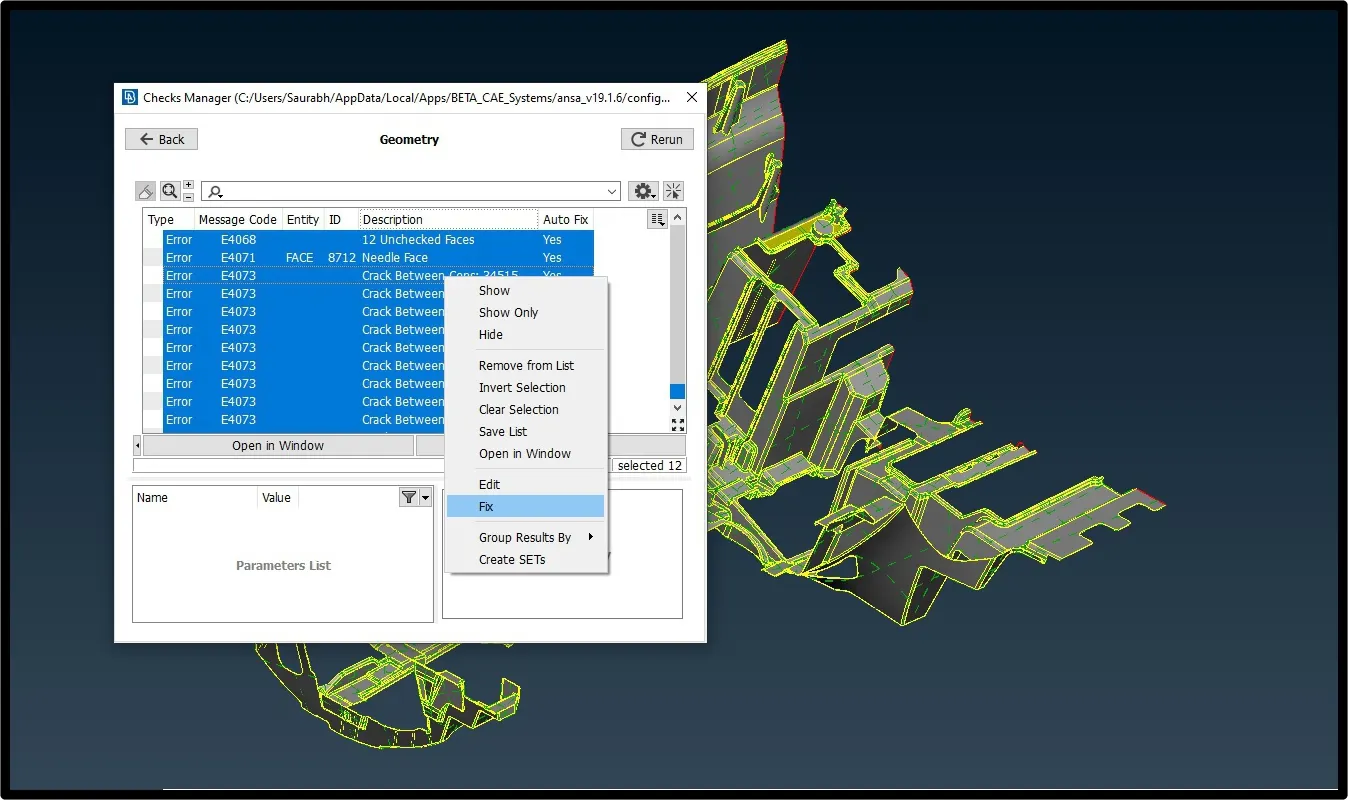
Next part is to preform geometry cleanup to remove unwanted surface, cons from geometry for smooth transition of mesh from each faces. Do it by using fix option and if still some aria need cleanup then solve that fix manually.
Quality Checks for Meshing:-
Now, our next step is to provide quality criteria for the solid and shell meshing. For this model our quality criteria is put in ANSA as per given below.
Mid-surfacing:-
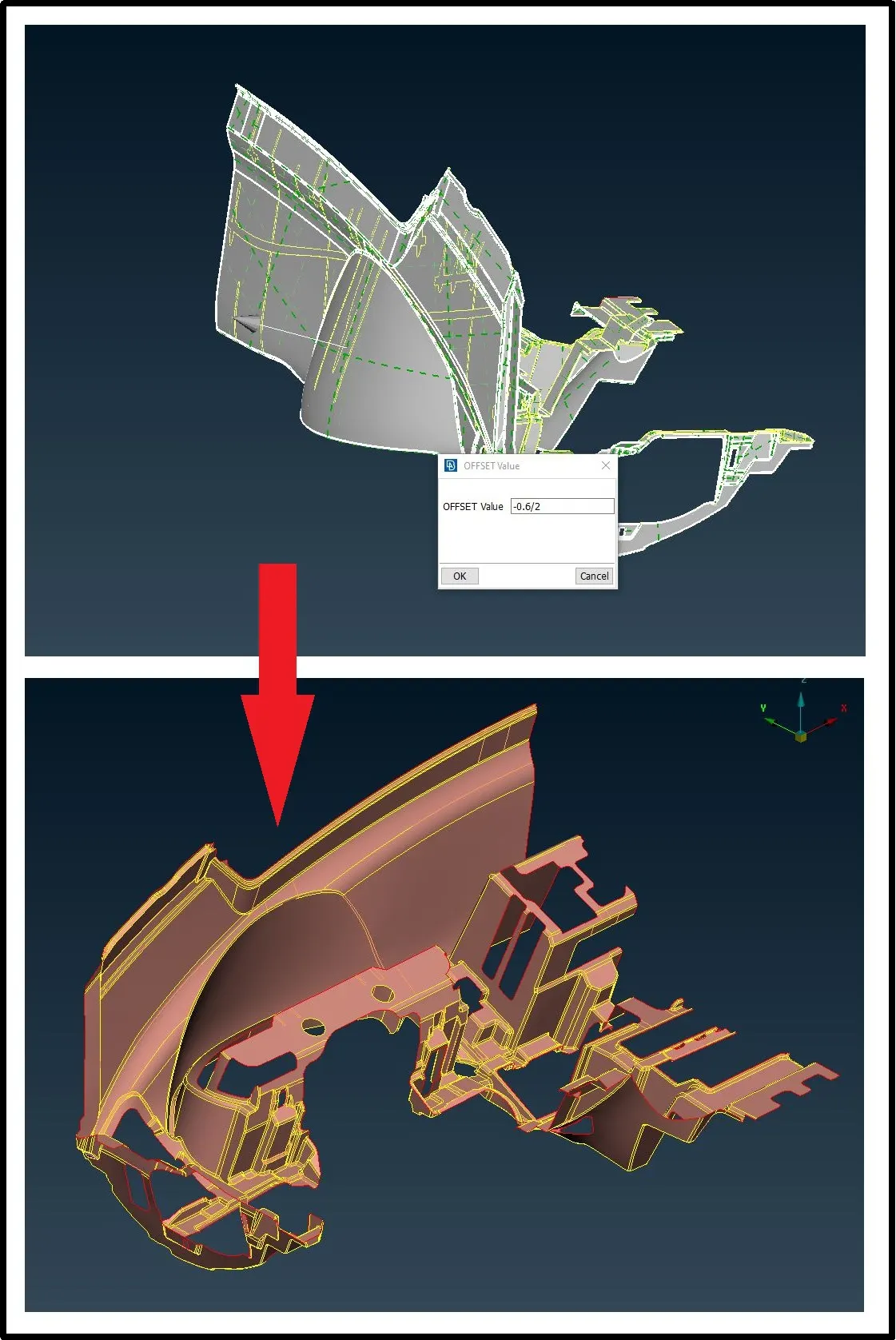
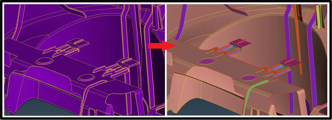
Now, we can extract mid surface from faces of the geometry one by one according to different thickness of individual section we will assign thickness to its property. In order to extract surface we can use manually we can use various method like offset, middle (single or multi) from faces option, we can also create middle curve by using middle button in curve section and then after create surface using those curves.
In this case, auto-mid is not possible as geometry is not closed volume therefor we will use offset option. For base surface we will use offset option with feature selection in order to select overall base surface and offset is half of the thickness.
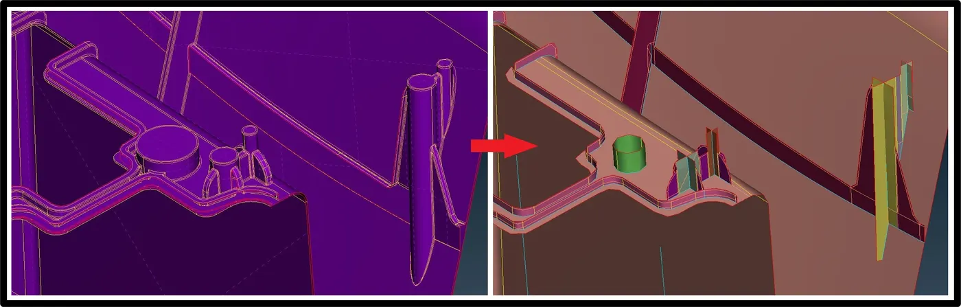
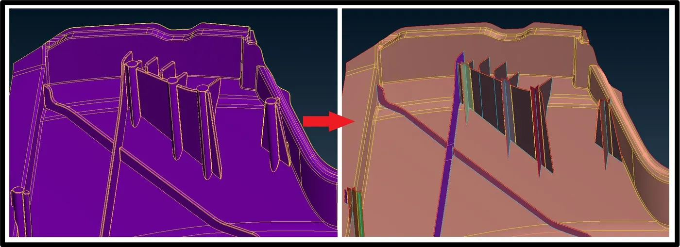
For other feature we will use middle or offset option, whichever user feel easy, to generate mid-surfaces and will connect those mid surface to base mid surface of dash board.
Meshing:-
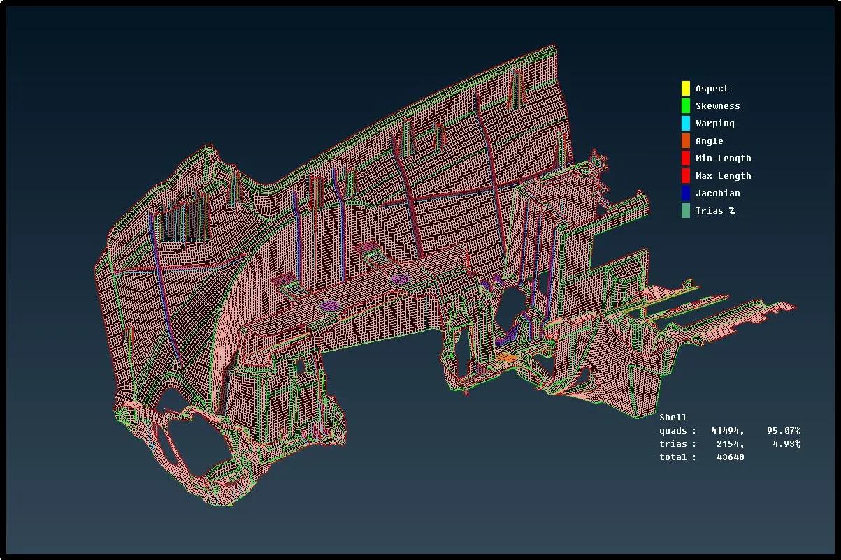
Now, we can mesh our extracted surfaces using best and batch mesh button.
First, mesh all the connected surface and clean that mesh using split, join, smooth, reconstruct option and then mesh base surface by hiding other mesh. In a bid to rearrange and remove tria elements we will use reconstruct button and select the button that we have to rearrange. Latter we are going to smooth it. We are going to follow above procedure one by one for each surface.
Set Property ID:-
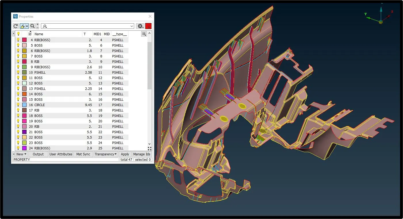
There are plethora different entity with various thickness in this part hence it is important to set separate PIDs to different section to provides different thickness is necessary.
Shell as solid:-
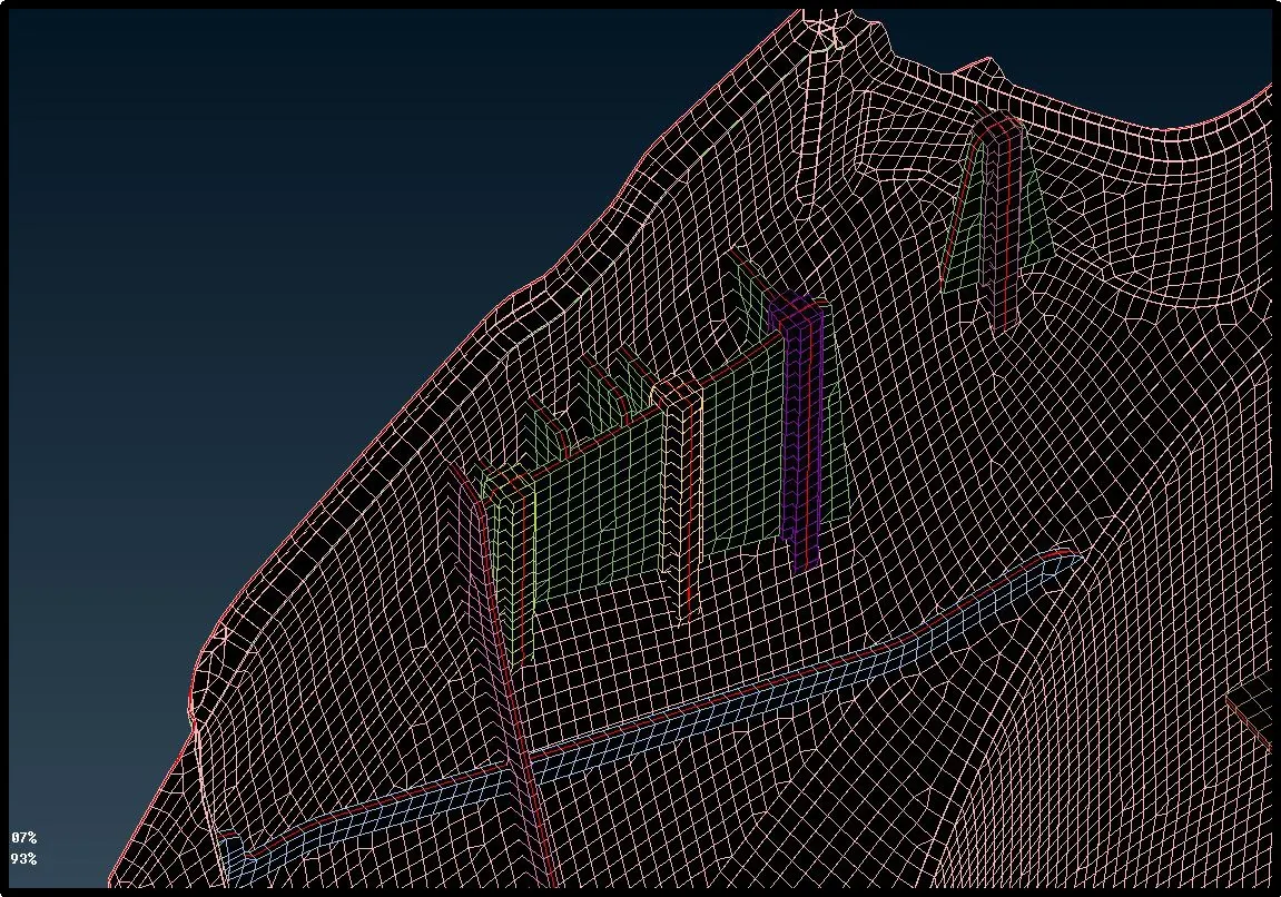
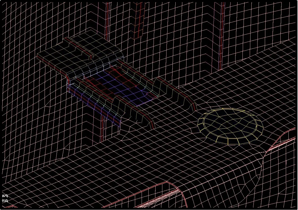
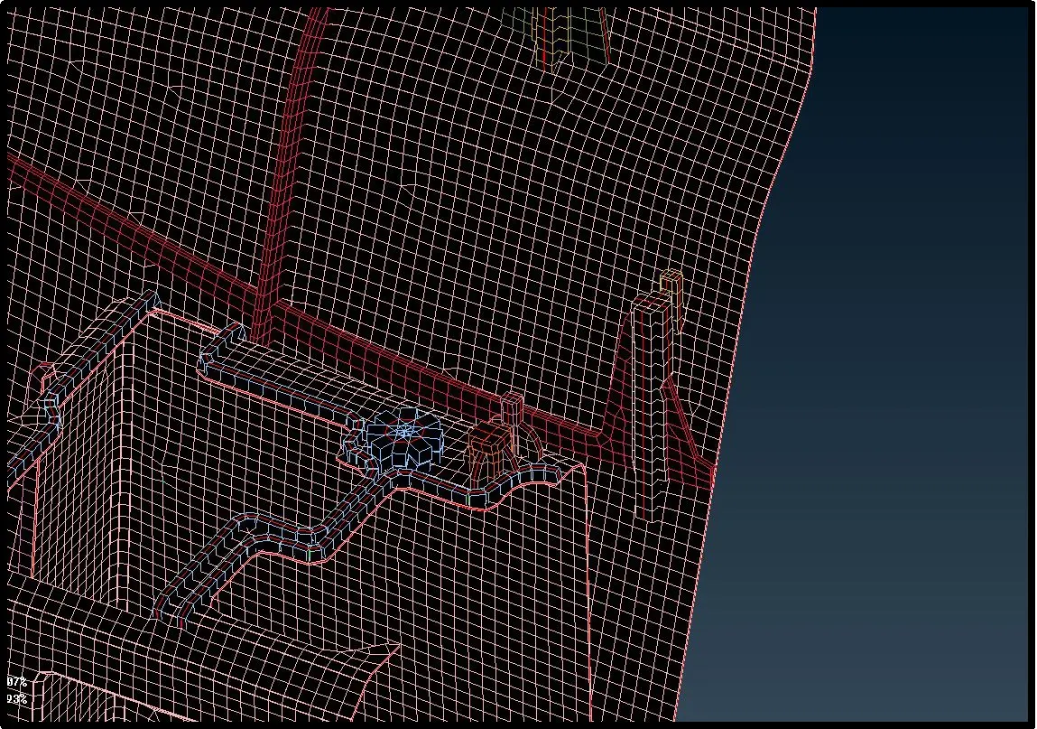
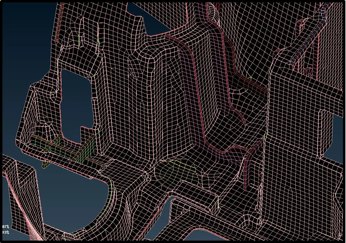
And last task to visualize thickness of the generated element. For thickness visualization we can convert shell mesh to solid with the help of thickness we had assign in property id of each surface. Go to Quality > Presentation parameter > Draw shell as solid and click apply.
Conclusion
Utilization of overall lectures knowledge to extract mid surface and to deploy mesh on given dash board model.