Project 1
PRE-PROCESSING OF A CAR DASH BOARD BY ANSA
AIM:The aim of this project is to perform pre-processing of a car dash board by using ANSA.
OBJECTIVE: Here, we are going to do the preprocessing of a vehicle dash board which is a plastic component.The method of preprocessing for a plastic component is explained below where most of the elements should follow the quality criteria.
METHODOLOGY:
- Import the geometry.
- Check for the errors.
- extract mid surface.
- Assign PIDS.
- mesh the plastic component within Quality criteria.
INTRODUCTION:
- A dashboard (also called dash, instrument panel (IP), or fascia) is a control panel usually located directly ahead of a vehicle's driver, displaying instrumentation and controls for the vehicle's operation.Where the dashboard originally included an array of simple controls (e.g., the steering wheel) and instrumentation to show speed, fuel level and oil pressure, the modern dashboard may accommodate a broad array of gauges, and controls as well as information, climate control and entertainment systems.Manufacturers such as BMW, Honda, Toyota and Mercedes-Benz have included fuel-economy gauges in some instrument clusters, showing fuel mileage in real time, which was limited mainly to luxury vehicles and later, hybrids.
PROCEDURE:
STEP 1: Import the geometry
- After opening ANSA, the geometry has to be imported to ANSA interface.
- Open the file command,search for the location of the model and then open.
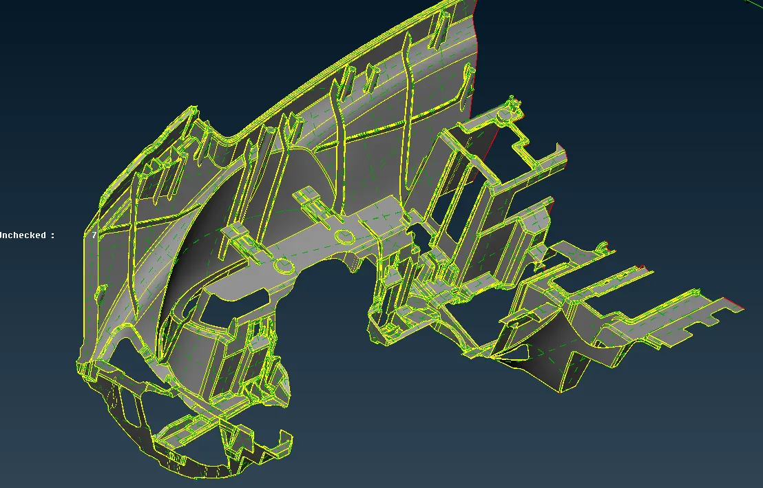
fig:Image showing the imported model.
STEP 2: Check for the errors.
- After importing into ANSA,every model has to check for the errors.
- If there are any errors rectify them manually or by automatically.
- Most of the errors can be solved in automatic method,some should be followed by the user.
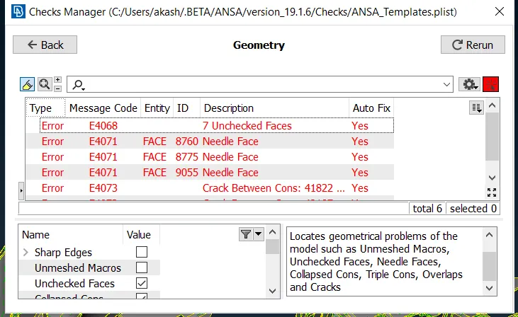
fig: Image showing errors in the geometry
- There are errors in the geometry,resolve them by autofix and manually.
- This should be done to extract midsurface for the component,Otherwise the mid surface cannot be extracted properly.
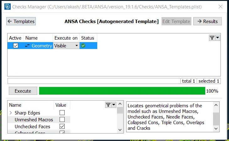
fig: image showing the model has no errors.
- Above image shows that the model is not having any errors,which means e can proceed to the next step.
- Every time before starting the midsurface the model should be clean.
STEP 3: EXTRACT MID SURFACE.
- There are many ways to extract midsurface.
METHODS OF MID SURFACE:
- Manual method
- Automatic method
MANUAL METHOD: In this the mid surface is extracted manually by selecting each face or entity.Example of this method is OFF SET methohd, middle option. In OFFSET method, one side of the model is selected and user have to give the offset by measuring the thickness of the model.Generally this is done when the model is not having the uniform thickness.In MIDDLE option,two surfaces are selected which are having uniform thickness.One or more surfaces can be done in this middle option.
AUTOMATIC METHOD: In this the model should be of closed volume,which means there should not be single cons only double cons should be present which is a sign of closed volume.Here,we give the minimum thickness of the model and the target element.We need to measure the minimum thickness in the model and enter the value.Mostly this process takes long time for ANSA to execute and it may crash.
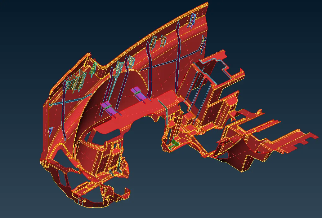
fig: Image showing the midsurface of the model.
- For this plastic component, mid surface is done manually i.e,by using offset and middle options.
- Thickness of the model is measured and offset by half of the distance.
- If there are identiacal parts we can use middle or middle multi option.
DOGHOUSE: There are some parts in the model whichare of different shape.For this the mid should be ectracted as shown.
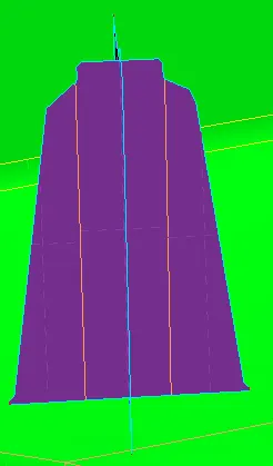
fig:image showing mid for doghouse
- For this type of surfaces the mid surface should be extracted and extended to the top surface for the model.
- User has to creat new surfaces and assign pids.Each doghouse may be of uniforn thickness or not should be check by the user.
STEP 4: ASSIGN PID
- After extracting mid surface, assign pid and thickness for the midsurface.
- To extract mid surface go to List-properties tab.
- Right click the mouse go to new-pshell-pshell option and create the pid.
- After creating give the thickness value and apply the pid to the model.
- Pid should be applied for each part seperately.
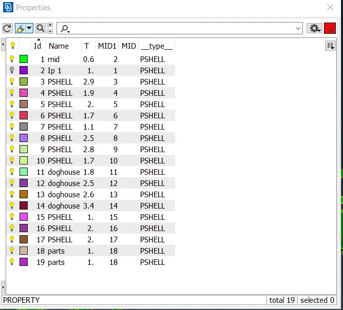
fig: image showing pids for each part with thickness assigned.
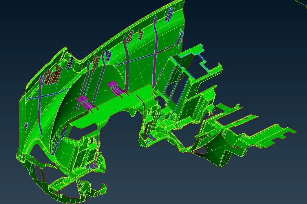
fig:Image showing the model in pid manager.
- From the above image we can observe that the model is shoein in pid mode.
- In this each part is of different colour and having different thickness.
ORIENTATION:
- In ANSA there are two orient colours.GOLD and GREY.
- Grey is positive in sign and gold is negative in sign.
- This can be visible only in entity mode.
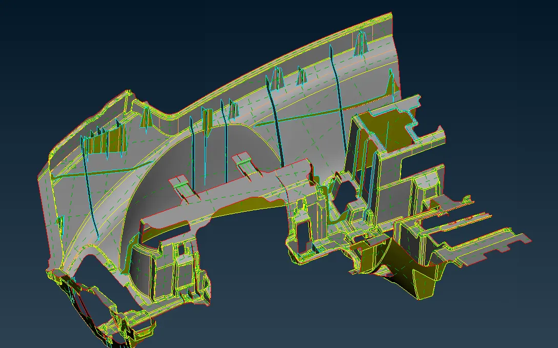
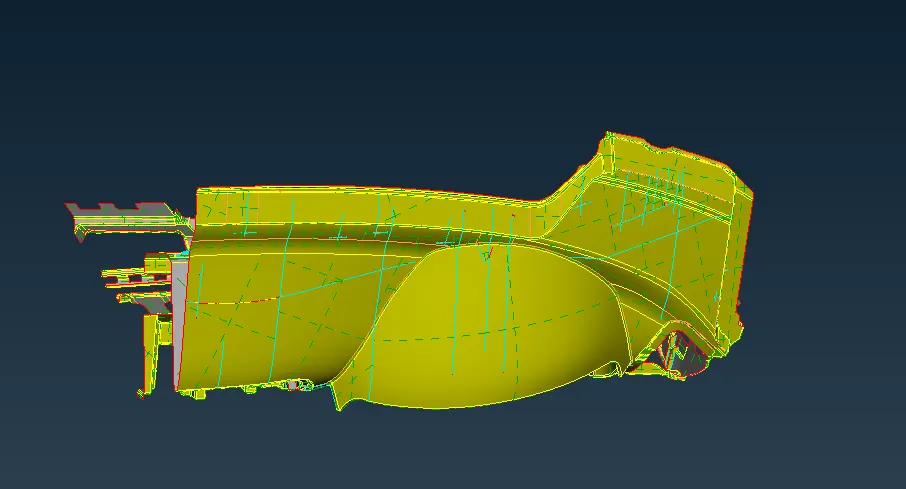
fig:Images showing model in orientation
STEP 5: QUALITY CRITERIA
- For preprocessing of any model there will be some quality we need to follow while doing meshing.
- Most of the elements should follow this Quality criteria to avoid off elements and good mesh flow.
- Off elements will occur when the element fail for any Quality issues.
- User has to resolve that elements by using mesh tools.
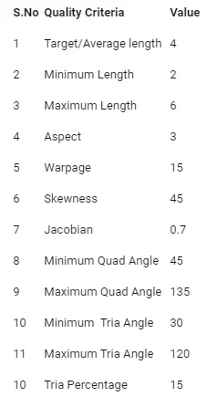
- This is the Quality criteria we need to follow while doing mesh.
- Apply this Quality criteria in Quality parameters by using f11 the keyboard.
STEP 6: MESH THE MODEL
- Always mesh the model from one end to another end.
- Make sure that whiile meshing mesh each part individually,which gives good mesh flow.
- If there is big part try to do some project cuts and make the join at the last.
- If off elements occurs try to solve them as much as you can.
- Do reconstruct and smooth after every mesh.
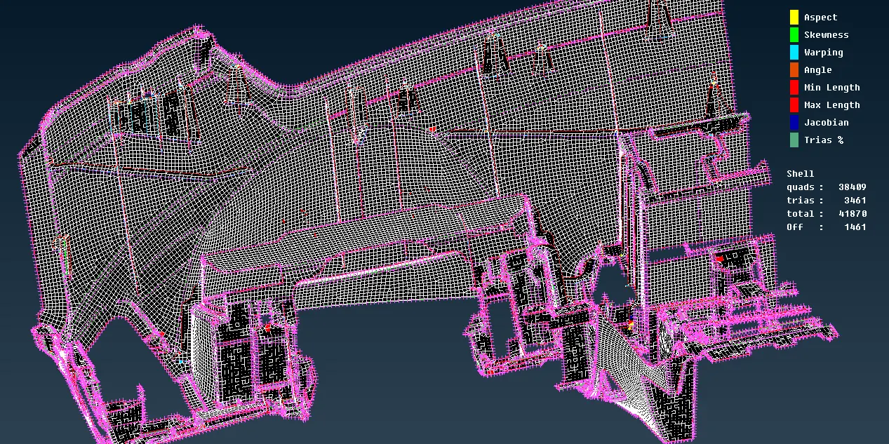
fig: Image showing meshed model
- In the above image we can observe that our model is mesh completely.
- But there are some off elements in the model which are failing for quality criteria.
- This has to be solved by the user.
- Use the options like split,move grids,swap,paste etc to solve the off elements.
- When you use off elements do smooth for good mesh flow.
- We can reduce the off elements by using some mesh tools like split,swap,paste,move grid.
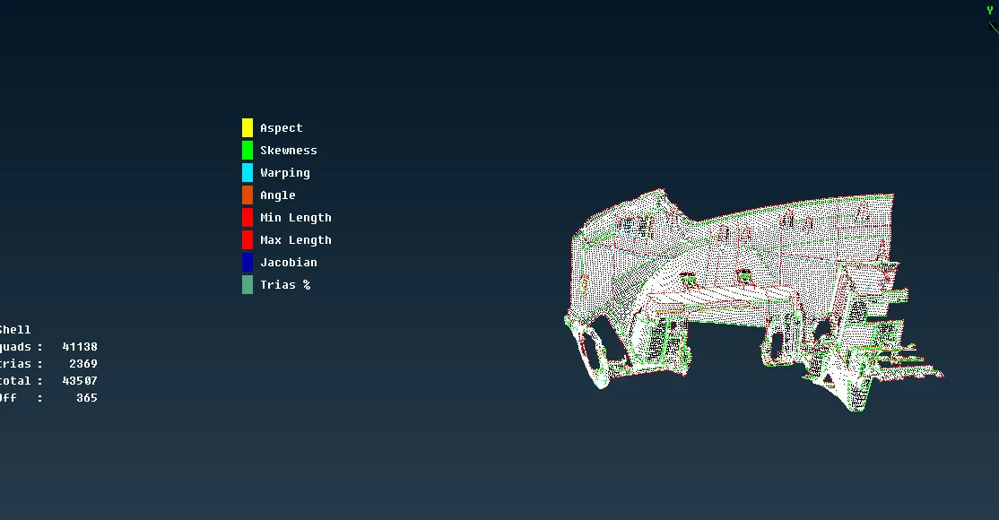
- After using mesh tool and reducing off elements we are left with 365 off elements.
- This is because of triple cons formed at the edge or perimeter to the model.
- These off elements are not preferred to solve due to geometry change which is not acceptable.
- Enable thickness after complete model is done.
- Draw shell as solid from Quality criteria.
MODEL BEFORE AFTER:
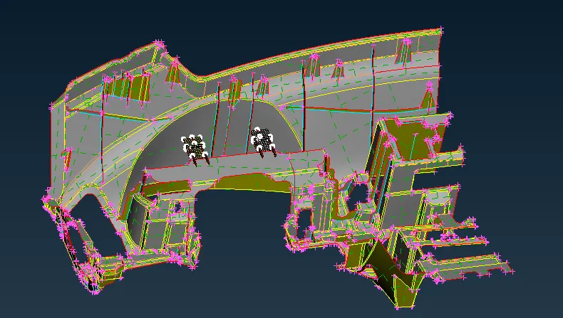
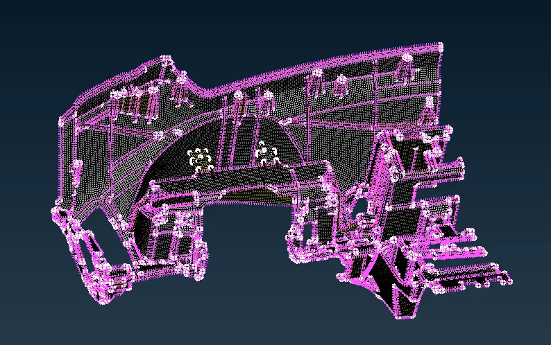
fig: Image showing complete model with thickness in topo and mesh mode
LEARNING OUTCOMES:
- Learnt how difficult plastic model is meshed.
- Able to know how to solve some of the complecated areas.
- Able to know mesh tools and other methods of midsurface extraction.
CONCLUSION:
A car dash bord is very important in interiror body of a car. This has to be taken into consideration as a plastic body as it is made up of plastic material. It has many parts which is usiful for the driver. Pre-processing is done for the car dash board.But we need to move on with some off elements because solving them will change the geometry which is not acceptable.The meshing of any complecated plastic material is same as above.
LINK OF THE PROJECT: https://drive.google.com/file/d/1wgd1lFAMgdv-2WbEhlv5FGuyyY_qG1yw/view?usp=sharing