Project 1 - Preprocessing on Instrumental Panel as per given quality Criteria by Using ANSA
AIM :
To Performing an Middle surface extraction & Meshing operation on the given Instrument Panel as per our quality Criteria by using ANSA.
OBJECTIVES :
Performing a Geometry Cleanuping on the given parent component.
Extracting the middle surface from the Parent Geometry.
Set the Elements Quality Parameters & Mesh Quality Parmeters.
Discritization of the entire model as per quality Criterias.
Assigning the thickness to the respective property card as per parent thickness.
CAD MODEL :
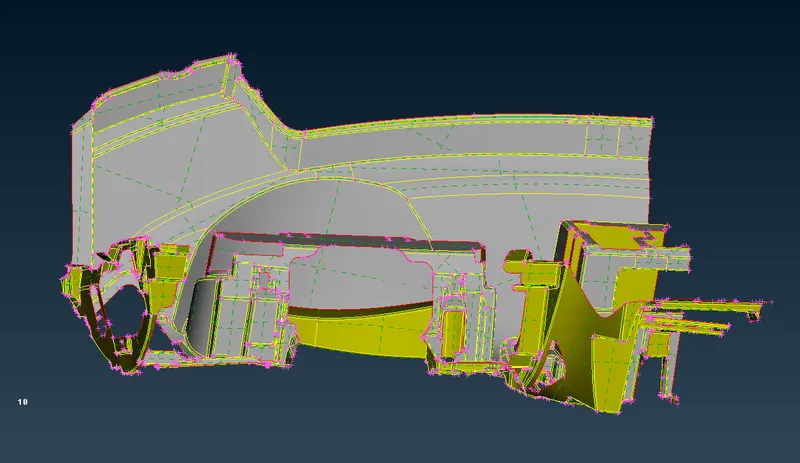
Open the ANSA software, import the appropriate file which is Automotive vehicle dashboard component or Instrumental Panel by using open graphical user interface option. Once file has opened, it will looks like as shown in the below image.
PROCEDURE FOR ATTAINING THE OBJECTIVES :
I) Geometry Cleanuping :
i) Topology Cleanup :
As we clearly noticed from the imported model, there's no surface or macros connectivity to each other, by results free edges are appeared on along the each & every perimeters edge. Inorder to rectify those issue, we will use "Topo" option under where "Faces" Sub modules & "Topology" modules.
Select the Topo option, followingly click left mouse button with box selection on entire model which are visible in the graphical window.
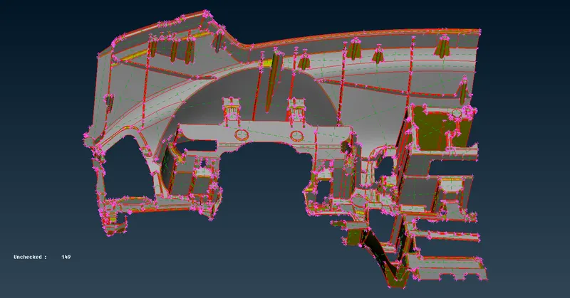
Once Topology cleanup has done, it will looks like as shown in below image. As we clearly able to view it from the below image, all macros are properly attached to each other except few regions.
Basically, by default Topo option have some tolerance value itself. If the two cons distance have less than which topo tolerance value, then by results both cons are connected to each other. Some times, if two more cons are presented on the same spot with less than the topo tolerance value, by results triple cons is generated.
Since, Instrumental panel were solid parts. Generally, there's no triple cons are presented in the solid component. So, we have fix those issues when we will checking the geometry.
ii) Geometry Checking :
Before going to discritization process, Make sure we have to checking the entire geometry if there's any geometrical issue are presented or not.
ANSA have by default template which have prebuilded some few important parameters, we have to select all those parameters except "Sharped Edges" and "Unmeshed Macros". Because, those parameters are no need for this case.
After complete the parameters selection, make sure keep "Visible On" from the "Execute On" option and then click Execute to which finding the errors from the visible geometry by ANSA itself.
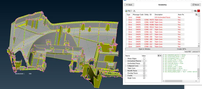
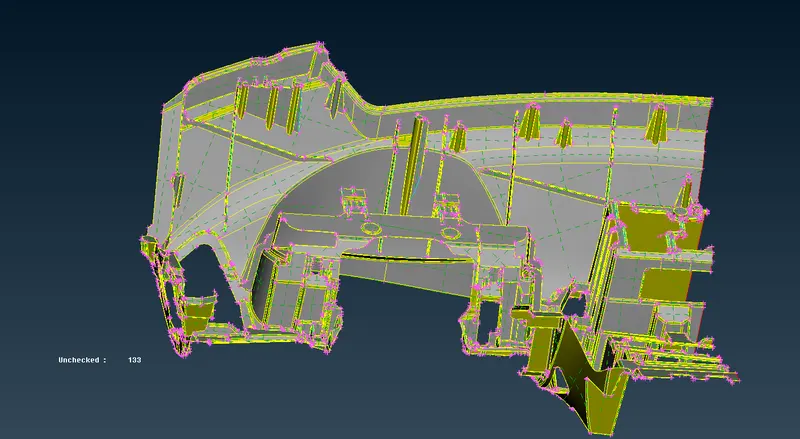
ANSA findout lots of issue from the visible parent component like triple cons, Unchecked faces, cracks between the surfaces & single cons as well.
Inorder to fix those errors, we have two option in our hand. One is Manual fix and another one automatic fix. In this case, We surely going to with automatic fix for Triple cons issue, because as we noticed from the check tab which is "Yes" for "Auto fix". Which means ANSA can able to fix the issues by itself.
Inorder to do fix those thing in automatically, we have to select all errors which are shown up and right click & followingly select fix option. Afterthat, ANSA have fix those issue in proper manner.
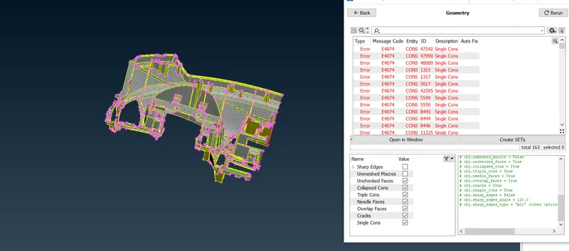
Again we have to cross check the geometry by using same template. As shown in the below image, still single cons are not yet to be fixed. We can't clear such thing, because as we notice from given geometry, we have only half a part of instrumental panel. There's no any closing surface, that's why those single cons error are presented.
II) Middle surface Extraction :
Generally, a middle surface are generated between at neutral position of the part. It will helps us to reduce the computational calculate time and also reduce the storage space.
Before going to extracting the middle surface from the parent geometry, make sure we have to check the parent component whether it's have proper orientation or not.
Here's a below image shows parent component has not a proper orientation on it.
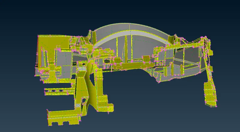
By using "Orientation" option under where "Faces" sub modules & "Topology" modules for which change the surface orientation of one side.
Yellow means Negative direction, Grey colour means Positive direction.
If we try to extracting the middle surface without proper orientation, by results we won't be extracting the middle surface with single shot even a component thickness has same throughout the part.
Inorder to avoid those things while we extracting the middle surface. Make sure keep surface orientation has proper.
After converting all surface into proper orientation, it will looks as shown in below image.
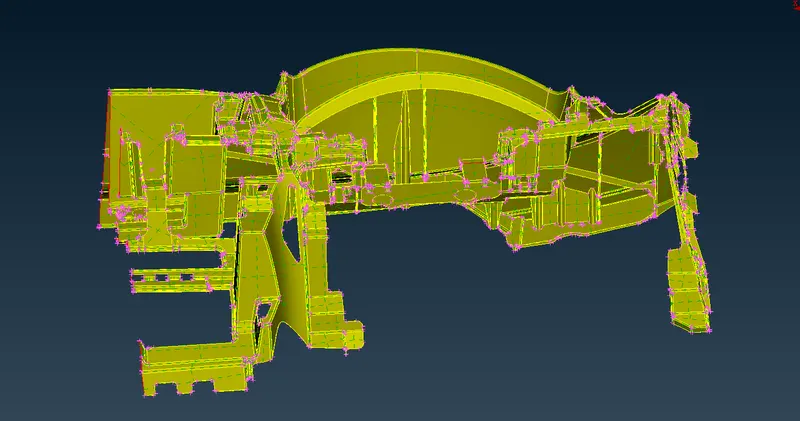
Since, given component have varying thickness & complex features like dog houses, ribs & few other featrures as well. So, Automatic middle surface extraction method might fails to generate the mid surface properly.
So, we have extracting the middle surface by manually in part by part.
i) By Using Offset Option :
First of all, we have to extract the mid surface for base surface by using Offset option. Make sure measure the thickness of the base surface before going to extracting the middle surface.
Select the "offset" option under which "Faces" sub modules & " Topology" modules. Select the surface which we gonna extract the mid surface like as shown in below.
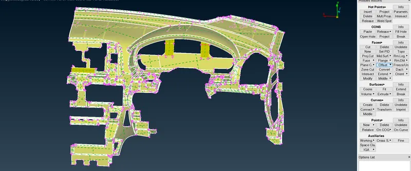
Provide the offset value which is half a thickness distance of parent component is 0.6.
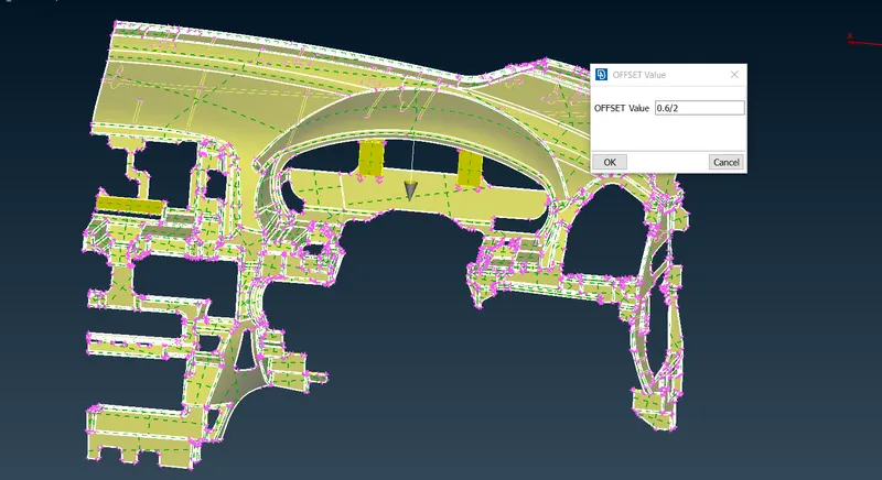
After extract the middle surface for base part, it will looks like as shown in below.
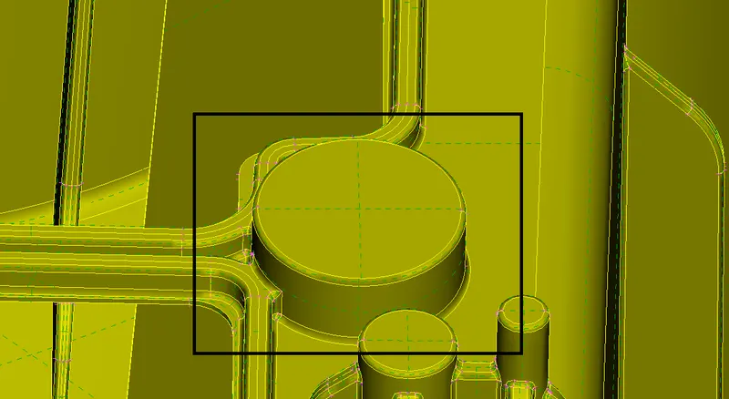
And Also we have a solid part like as shown in the below, we have to offset the surface at 0.5 mm towards inside direction.
Select Offset option, followingly select the appropriate outer solid part surface and then provide the offset distance value which is 0.5. Then Click to extract the mid surface for solid part
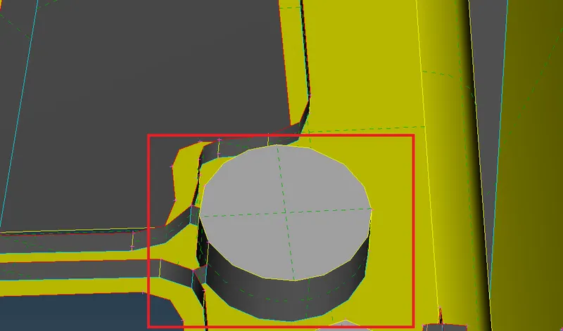
After Extracting the mid surface for Solid Cylinder part, it will looks like as shown in the below image. This is How we are represents the solid part in the middle surface.
Similarly, we have to use this offset option whereever it might be working properly by same manner which we saw in previously.
ii) By Using Middle Face :
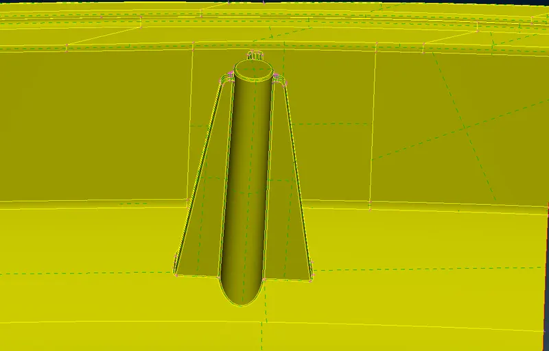
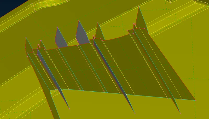
Dog Houses is one of the important subparts in the instrumental panel. We have to generate the middle surface properly with capturing the features.
By using "Middle Face " Option under where Faces sub moduels & Topology module to which extract the mid surface for Ribs in the dog Houses.
Once we created the mid surface, by using "Extend" option to which extend the mid surface for getting an proper one.
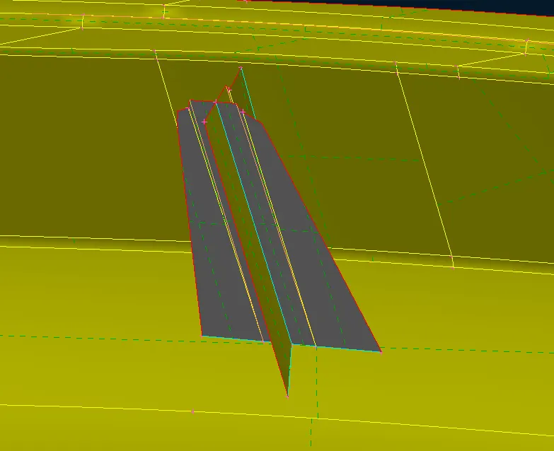
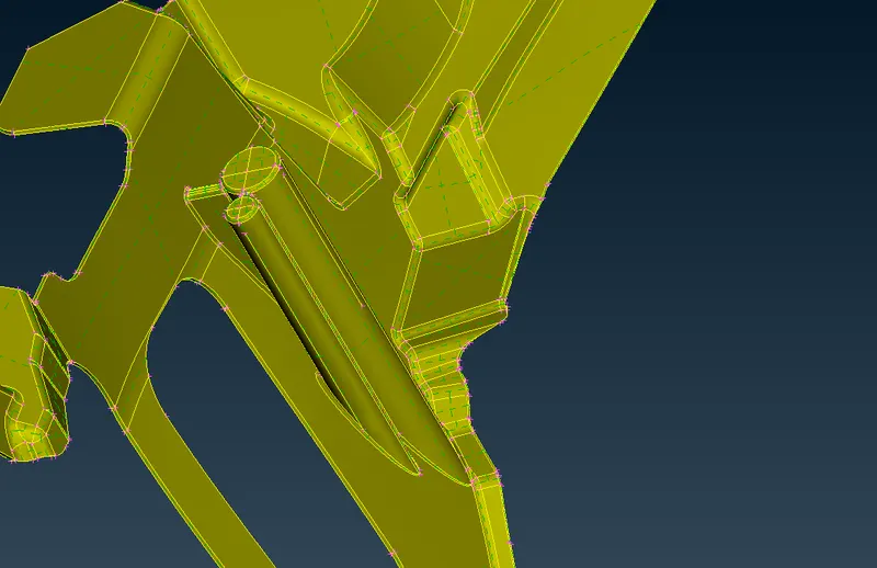
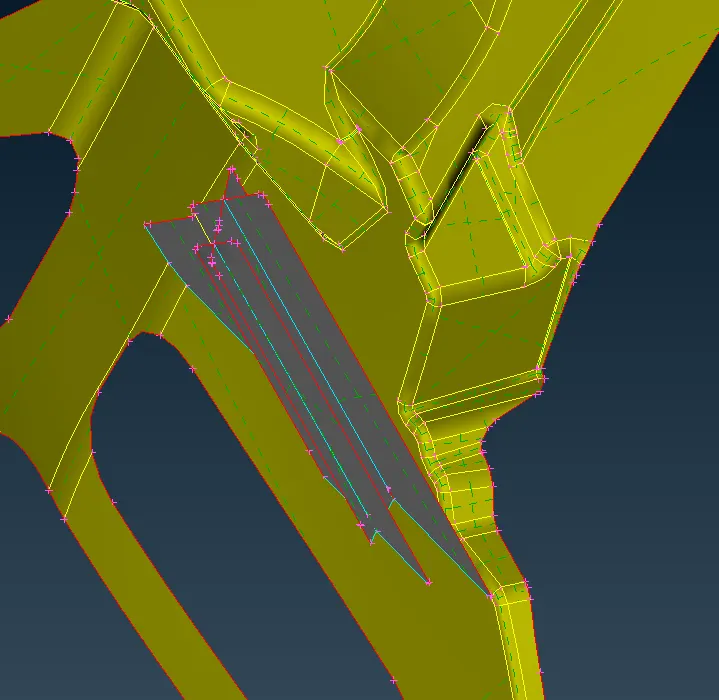
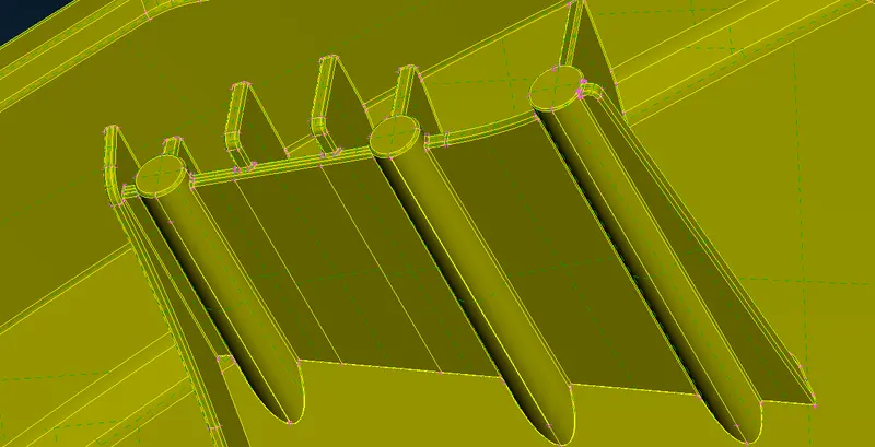
Here below few snaps are showing before & after the extracting the mid surface.
Simple Dog House :
Dog Houses on the Inclined surface :
Multiple Dog House :
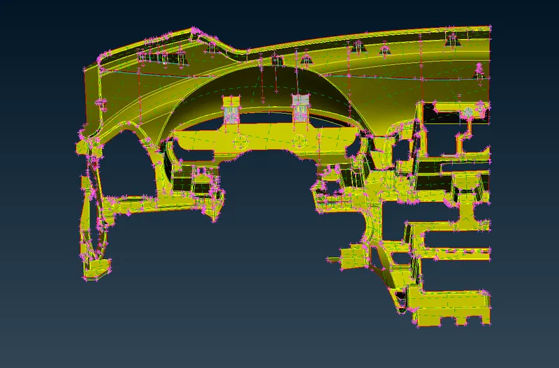
Complete Middle surface for Instrumental Panel :
III) Setting the Quality Parameters & Mesh Parameters :
i) Mesh Parameters :
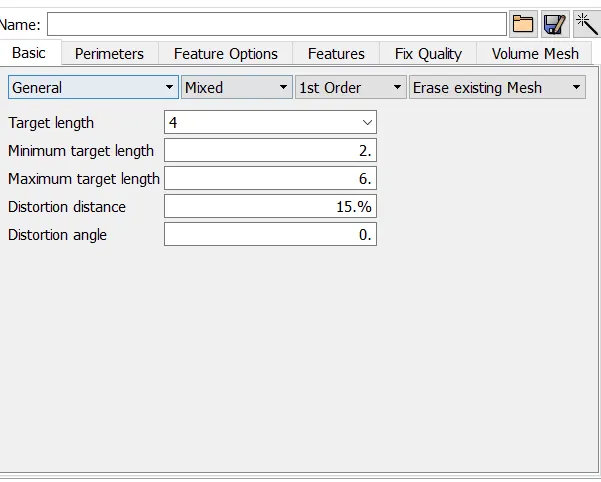
Before going to performing the meshing operation, make sure we have to setting the mesh parameters like as shown in the below.
When we perform meshing operation, initially a mesh algorithm has trys to generating the mesh elements as per macros or perimeter node distances.
If we trys to improve the mesh quality by using reconstruct or reshape or Improve option, that time those algorithms are try to capturing the elements as per given parameters even if the macros or perimeters node distance is different.
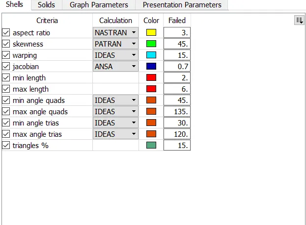
ii) Quality Criterias :
Make sure we have to enabling all important quality parameters & provide the appropriate values in numerically. It's helps us to checking the failure of the elements when we perform an meshing operation.
IV) Discritization of the model :
Basically, To divide the entire model into infinitesimal control volume, that framework is called meshing. This process is called discritization.
First of all, Make sure keep the resolution of components to which distance between the two nodes is equal to the target element length by using "Length" option under the "Perimeter" sub module & "Mesh" module.
By using Best or Spot algorithms with Mixed elements to which performing the meshing operation on surface by surface along with checking the quality of each & every elements is necessary.
If generated elements are not got proper orientation flow or any elements has been failed due to any of the given element quality criterias. We have to use reconstruct option or Improve option to which remesh on it, by results we get proper mesh flow orientation of elements and also avoid the element failing.
If any of the feature lateral distance is less than the minimum element length criterias. Then, We have manually defeaturing out little bit for which avoiding the elements faling due to minimum element length parameters.
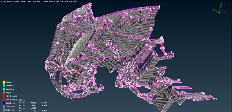
In this Dashboard components, as we clear noticed from the above image. Some elements are failing for minimum element lengh, jacobian, Aspect & Angle. This failures are occurs due to the triple cons to created the sharp edges. Most of the elements are failing due to Minimum element length criterias.
If Minimum element length issue are presented in the FE model. By results, simulation time is increased.
V) Assigning the thickness :
Measure the original thickness of the parent geometry at each & every sub parts. Assigning the new property card for each mid surfaces as per thickness of parent geometry.
Assigning the appropriate thickness for each & every property card.
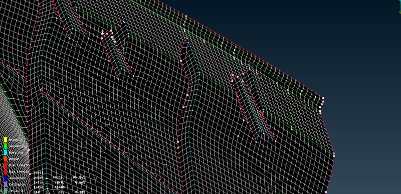
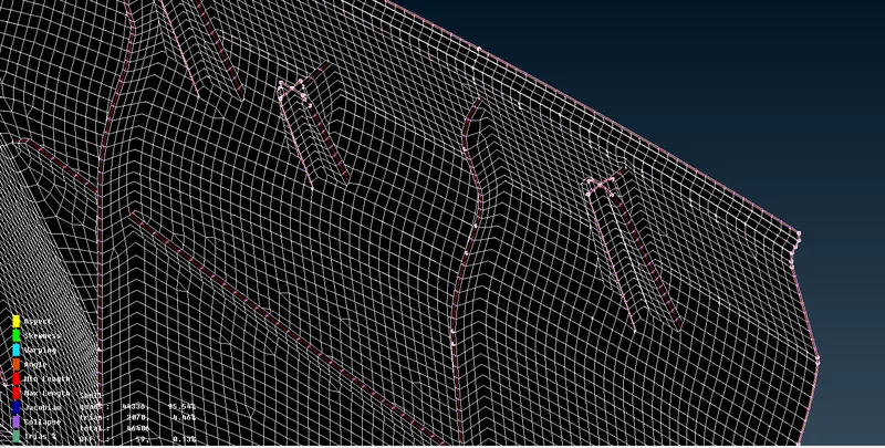
Inorder to visualize the thickness from the FE Model, we have enable the "Draw shell as solids" option under which "Presentation parameters" and apply on it.
Without Thickness :
With Thickness :
CONCLUSION :
Successfully done the preprocessing operation on the given Instrumental Panel or Dashboard model like Checking the geometry error from the model, Middle surface Extraction from the parent component, Meshing and then assigning the thickness to the middle surface.