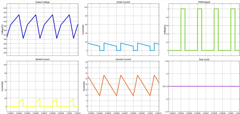
Project 1
Project Number 1:
1)
The fiirst step is the calculation of the load Resistor: since the output power Pout = Pin = 500 W and Output Voltage is 30V then the R_load is:
R_load = (Vout)^2/Pout = 1.8 ohm
Input voltage is variable from 40 V to 50 V => Duty ratio calculations...
Vout/Vin_max = 30/50 = 0.6
Vout/Vin_min = 30/40 = 0.75
SWITCHING FREQUENCY
A frequency of 100 KHz is choosen to have components with reasonable values and not too high to avoid commutation problems at the MOSFET
INDUCTOR CALCULATION
The average Output Current that correspond to Inductor Average Current is: Vout/R_load = 30/1.8 = 16.6 A
To have a inductor current ripple that is less than 30% of the average inductor current I use this formula(use D = 0.6):
L = (1 - D)*Vout/(f * DELTA_I) =
(1 – 0.6)*30/(100000 * 0.3 * 16.6) = 24 uH
OUTPUT CAPACITOR CALCULATION
With the formula is
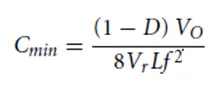
and the output voltage ripple will be less than 5%
Cmin = (1 - 0.6)*30/(8 * 0.05 * 24u*100000 * 100000) = 125 uF
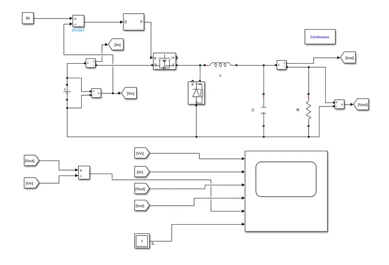
Simulink Schematich:
Results:
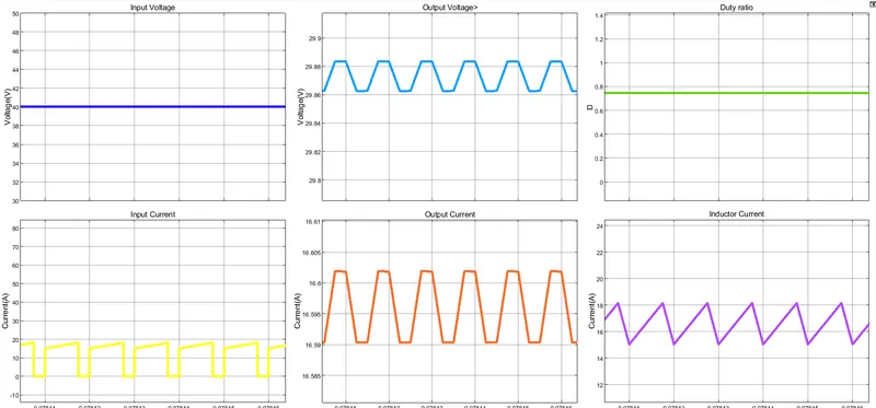
Case Vin = 40 V:
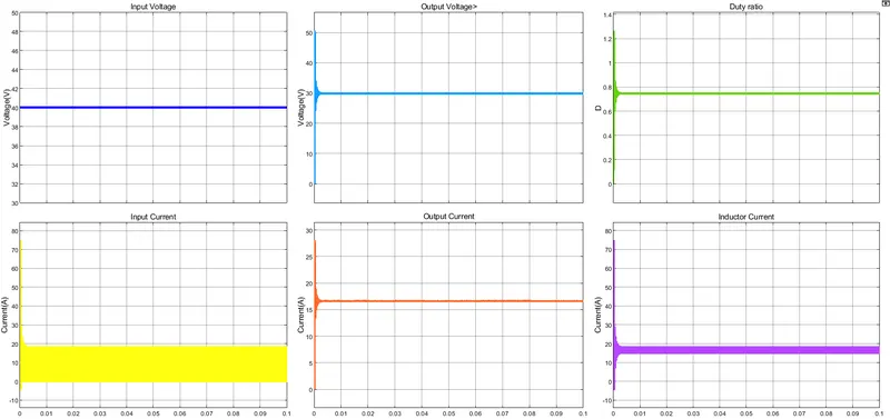
with zoom:
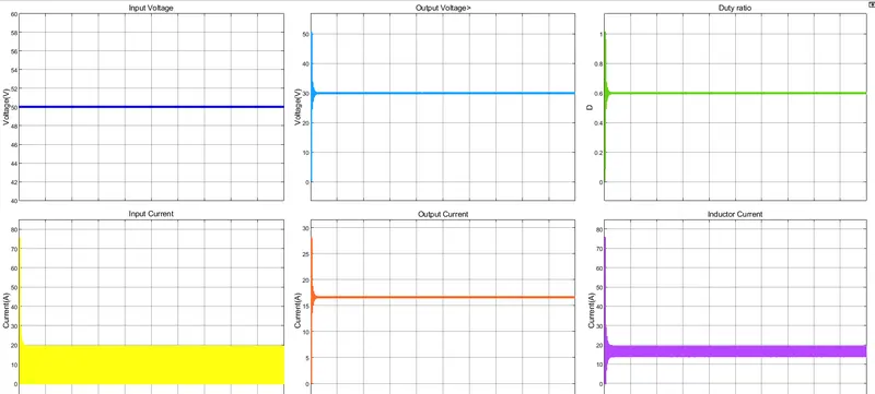
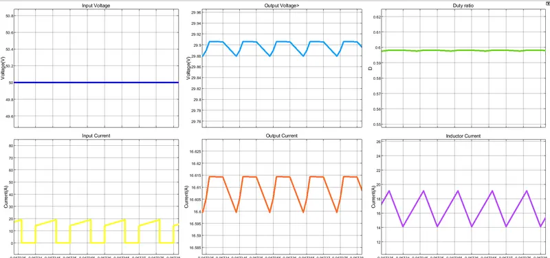
Case Vin = 50V:
With zoom:
Project Number 2:
1) This problem can be summarise with the following specifications:
- Input Voltage: Range from 20 V to 30 V
- Output Voltage: 40V
- Power input = Power Output = 600W (case Ideal Power Converter): the output load can be approximated with a resistor of value R = Vout^2/Pout = 40^2/600 = 2.6 ohm
I use a 100 kHz switching frequency for PWM Mosfet Switch
The duty ratio for a boost converter is:
Vout/Vin = 1/(1-D) with D the Duty cycle of the PWM input signal
In the specification the input voltage is variable from 20V to 30V:
- with Vin = 20 V => Vout/Vin = 40/20 = 2 => D = 0.5
- with Vin = 30 V => Vout/Vin = 40/30 = 1.33 => D = 0.25
In conlusion: 1.33 < Vout/Vin < 2 and 0.25<D<0.5
Design the switching inductor such that the current is continuous in the worst case scenario
With I_L(inductor current) = Vin/((1-D)^2*R).
- For D = 0.25 => I_L = 30/((1 - 0.25)^2*2.6) = 20.51 A
- For D = 0.5 => I_L = 20/((1 - 0.5)^2*2.6) = 30.76 A
To have a current inductor ripple of 40%:
- DELTA_I_L = 20.51 * 0.4 = 8.2 A for Vin = 30 V
- DELTA_I_L = 30.76 * 0.4 = 12.3 A for Vin = 20V
for the design of L the formula is:
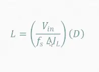
then I consider the case with L higher
- with Vin = 30 V => L = 30/(100000*8.2)*0.25 = 9uH
- with Vin = 20 V => L = 20/(100000*12.3)*0.5 = 8.1uH
=> I choose an inductor with L = 20uH
Design an output capacitor such that the output voltage ripple is less than 10 %
For the Output capacitor I consider the following formula:
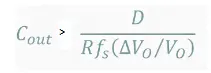
To have a ripple Output Voltage of maximun 10% I consider the only case with greater D:
- with Vin = 20 V => D = 0.5 => Cout = 0.5/(2.6 * 100000 * 0.1) = 1.92 uF
I choose Cout = 10 uF
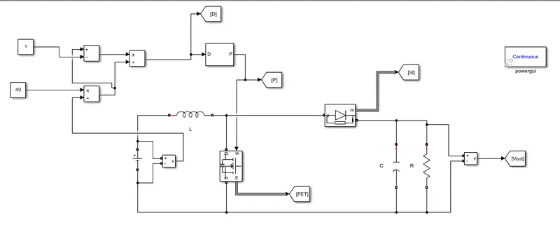
Simulink schematic
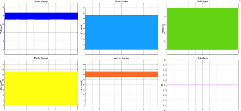
Results:
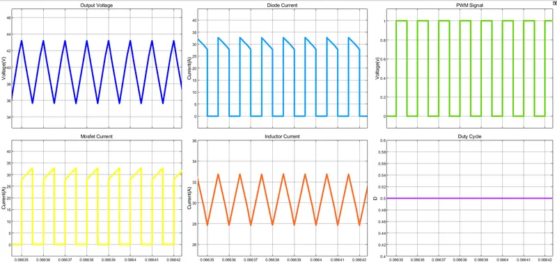
Case Vin = 20 V:
with zoom:
Case Vin = 30 V:
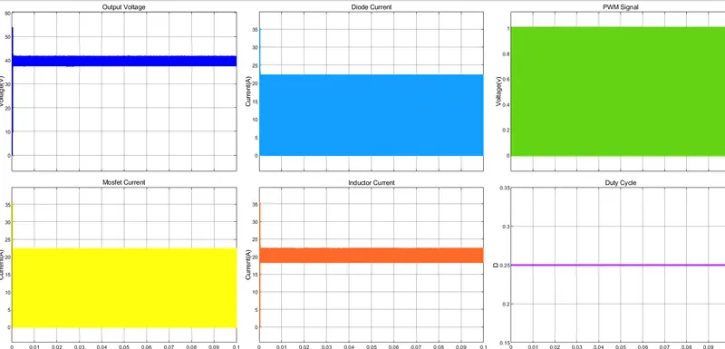
with zoom:
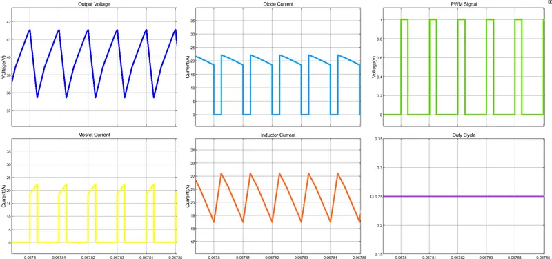
Project Number 11:
1) This problem can be summarise with the following specifications:
- Input Voltage: Range from 200 V to 300 V
- Output Voltage: 400V
- Power input = Power Output = 4 KW (case Ideal Power Converter): the output load can be approximated with a resistor of value R = Vout^2/Pout = 400^2/4000 = 40 ohm
I use a 50 kHz switching frequency for PWM Mosfet Switch
The duty ratio for a boost converter is:
Vout/Vin = 1/(1-D) with D the Duty cycle of the PWM input signal
In the specification the input voltage is variable from 200V to 300V:
- with Vin = 200 V => Vout/Vin = 400/200 = 2 => D = 0.5
- with Vin = 300 V => Vout/Vin = 400/300 = 1.33 => D = 0.25
In conlusion: 1.33 < Vout/Vin < 2 and 0.25<D<0.5
Design the switching inductor such that the current is continuous in the worst case scenario
With I_L(inductor current) = Vin/((1-D)^2*R).
- For D = 0.25 => I_L = 300/((1 - 0.25)^2*40) = 13.3 A
- For D = 0.5 => I_L = 200/((1 - 0.5)^2*40) = 20 A
To have a current inductor ripple of 40%:
- DELTA_I_L = 13.3 * 0.4 = 5.32 A for Vin = 300 V
- DELTA_I_L = 20 * 0.4 = 8 A for Vin = 200 V
for the design of L the formula is:
then I consider the case with L higher
- with Vin = 300 V => L = 300/(50000*8.2)*0.25 = 182 uH
- with Vin = 200 V => L = 200/(50000*12.3)*0.5 = 162uH
=> I choose an inductor with L = 200uH
Design an output capacitor such that the output voltage ripple is less than 10 %
For the Output capacitor I consider the following formula:
To have a ripple Output Voltage of maximun 10% I consider the only case with greater D:
- with Vin = 200 V => D = 0.5 => Cout = 0.5/(40 * 50000 * 0.1) = 2 uF
I choose Cout = 10 uF
Simulink schematic
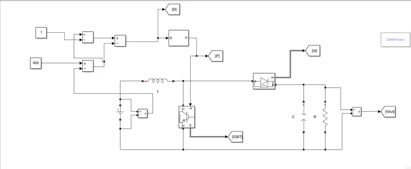
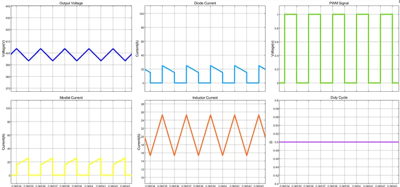
case Vin = 200V
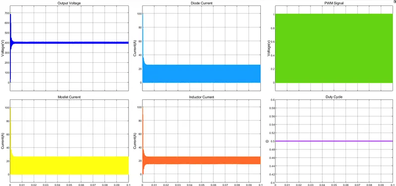
WITH ZOOM:
cASE vIN = 300V
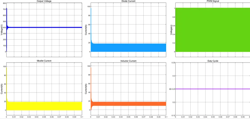
With zoom: