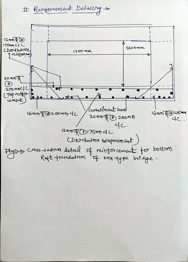
Project 1
Aim: - To design the raft foundation of the bridge underpass for the given dimension. All tye load calculation shall be done according to IRC-6 and the structure is analyzed for live load by effective width method for design.
Combinations for ULS, SLS rare & quasi-permanent are also needed to be done.
| Design Data | ||||||||
| No. of cells | = | 1 | ||||||
| Clear Span | = | 12.00 | m | |||||
| Clear Height at the outer edge | = | 5.50 | m | |||||
| Clear Height at the median edge | = | 5.50 | m | |||||
| Width of Box | = | 12.50 | m | |||||
| Carriage Width | = | 11.50 | m | |||||
| Width of crash barrier | = | 0.00 | m | |||||
| Width of footpath/safety kerb | = | 0.00 | m | |||||
| Width of Haunch | = | 0.20 | m | |||||
| Depth of Haunch | = | 0.20 | m | |||||
| Thickness of Wearing coat | = | 0 | m | |||||
| Thickness of fill over top slab | = | 1.5 | m | |||||
| Depth of Top Slab | = | 0.600 | m | |||||
| Depth of Bottom Slab | = | 0.650 | m | |||||
| Depth of External Vertical Wall | = | 0.600 | m | |||||
| Safe bearing capacity | = | 80.00 | KN/m^2 | |||||
| Spring Constant | Bowles book : 40 x FS x SBC (FS=2.5) | = | 1066.667 | KN/m | ||||
| Setellement | = | 0.075 | m | |||||
| Density of concrete | = | 25.00 | KN/m^3 | |||||
| Bulk Density of soil | = | 20.00 | KN/m^3 | |||||
| Density of submerged soil | = | 10.00 | KN/m^3 | |||||
| Density of Profile corrective course | = | 22.00 | KN/m^3 | |||||
| Density of fill | = | 20.00 | KN/m^3 | |||||
| Coefficient of active earth pressure | = | 0.5 | ||||||
| Length of the box considered for design | = | 1 | m | |||||
| Design Parameter | ||||||||
| Grade of Concrete | = | M30 | ||||||
| Grade of Steel | = | Fe 500 | D | |||||
| Clear Cover for Top slab | = | 45 | mm | |||||
| Clear Cover for Walls | = | 45 | mm | |||||
| Clear Cover for Bottom slab | = | 75 | mm | |||||
| E of concrete | = | 31000 | Mpa | |||||
| Load Calculations | ||||||||
| Self wt of bottom slab per meter square | = | 20.00 | kN/m2 | |||||
| Self wt of top slab per meter square | = | 15.00 | kN/m2 | |||||
| Self wt of abutment wall per meter length | = | 165.00 | kN/m | |||||
| Self wt of abutment wall per meter square | = | 12.50 | kN/m2 | |||||
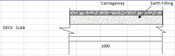
STAAD-Pro modeling:-
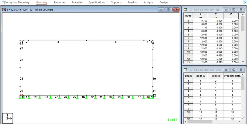
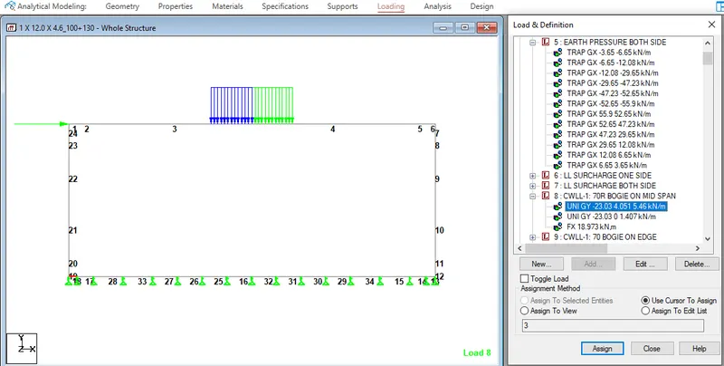
The box is modeled as a plane frame structure taking the center line dimensions of the structure in STAAD-Pro. As the length of the box underpass is comparatively more than its width so the under-pass will be analyzed for unit length and then the design will be implemented to the entire structure. Since the soil is fully resting on soil, the discrete spring supports are provided below the base slab to model the earth pressure. The stiffness of the soil springs is calculated based on a sub-grade modulus of the soil available at the base. The size of the members is assigned as per assumptions.
MODEL:-
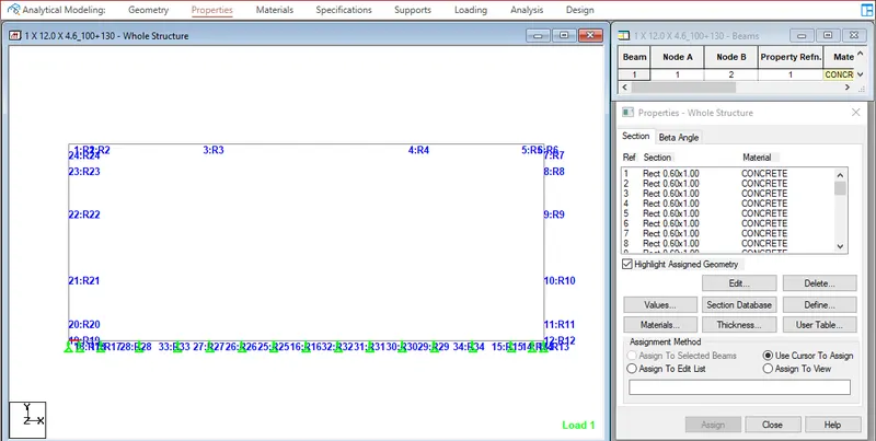
Properties:-
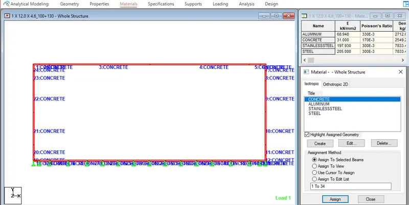
The sizes of the top slab, sidewalls & bottom slab are assumed and provided using the properties tab in STAAD-Pro.
Materials:-
Supports:-
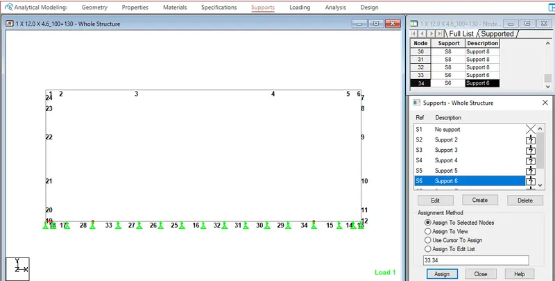
The supports are provided at the bottom of the foundation. The KFY values are calculated depending on the distance between the supports. Half of the distance on either side of the support is determined & KFY values for that distance are calculated. The horizontal release is also provided in support1.
Load calculation:-
Dead Load:-
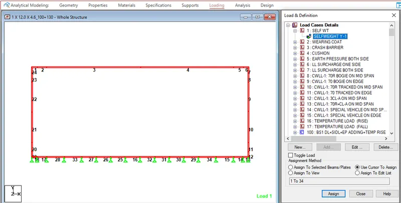
The dead load on the structures is calculated actually by finding the volume of the members and multiplying it by the density of the concrete. In STAAD-Pro it can easily be calculated by using the command self-weight with the factor -1
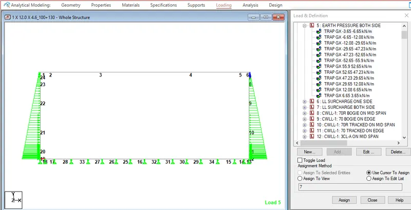
| Earth Pressure: | ||||||||
| Height of soil | = | 6.900 | m | |||||
| The angle of internal friction | = | 30.00 | o | |||||
| Coefficient of earth pressure at rest | = | 0.500 | ||||||
| Earth pressure intensity at the top | = | 0 | kN/m2 | |||||
| Earth pressure intensity at the bottom | = | 69 | kN/m2 | |||||
| Height of surcharge(due to LL) | = | 1.20 | m | |||||
| AS PER IRC:6-2010 | ||||||||
| For 70R-Wheeled Boogie | ||||||||
| Clear distance | = | 1.07 | m | |||||
| Width of the track (transverse to traffic dir.) | = | 0.81 | m | |||||
| Width of the track (along traffic dir.) | 0.26 | m | ||||||
| Total width of the vehicle | = | 2.79 | m | |||||
| width center to center of wheel | = | 1.98 | m | |||||
| For 70R - Tracked | ||||||||
| Clear distance | = | 1.20 | m | |||||
| Width of the track (transverse to traffic dir.) | = | 0.84 | m | |||||
| Width of the track (along traffic dir.) | 4.57 | m | ||||||
| Total width of the vehicle | = | 2.90 | m | |||||
| width center to center of wheel | = | 2.06 | m | |||||
| For CL - Tracked | ||||||||
| Clear distance | = | 1.20 | m | |||||
| Width of the track (transverse to traffic dir.) | = | 0.84 | m | |||||
| Width of the track (along traffic dir.) | 4.57 | m | ||||||
| Total width of the vehicle | = | 2.90 | m | |||||
| width center to center of wheel | = | 2.06 | m | |||||
| For CL-A wheeled | ||||||||
| Clear distance | = | 1.30 | m | |||||
| Width of the wheel (transverse to traffic dir.) | = | 0.50 | m | |||||
| Width of the wheel (along traffic dir.) | 0.25 | m | ||||||
| Total width of the vehicle | = | 2.30 | m | |||||
| width center to center of wheel | = | 1.8 | m | |||||
| For Special Vehicle | ||||||||
| Clear distance | = | 0.60 | m | |||||
| Width of the wheel (transverse to traffic dir.) | = | 0.16 | m | |||||
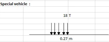
| Width of the wheel (along traffic dir.) | 0.27 | m | ||||||
| Total width of the vehicle | = | 3.00 | m | |||||
| width center to center of wheel | = | 1.8 | m | |||||
| For 70R-Wheeled Boggie | |||||||||
| Impact factors | |||||||||
| Impact factor = | 24.19% | ||||||||
| Effective Dispersion Width: | |||||||||
| Dispersion of loads through fills and wearing coat (at 45° angle): | |||||||||
| beff | = | b + 2 * (wc + D + s) | |||||||
| b | = | tyre width along traffic flow | = | 0.263 | m | ||||
| wc | = | wearing coat | = | 0 | m | ||||
| D | = | Overall depth of slab | = | 0.600 | m | ||||
| s | = | thickness of soil above box | = | 1.5 | m | ||||
| Hence, dispersion width | = | 4.463 | m | Along the span | |||||
| Calculation of effective width: | |||||||||
| beff = | k * x (1 - x/lo) + b1 | ||||||||
| k = | constant depending on b/lo | = | 2.233651 | (for b/lo = | 0.9921 ) | ||||
| lo = | effective span | = | 12.60 | m | |||||
| x = | Distance of centre of gravity from nearest support | = | 6.3 | m (for max. moment case) | |||||
| x = | 0.61 | m (for max. vertical load case) | |||||||
| b = | tyre width across traffic flow | = | 0.81 | m | |||||
| wc = | wearing coat | = | 0 | m | |||||
| b1 = | width of tyre + 2 x thickness of w.c. | = | 3.81 | m | |||||
| Hence, beff for max moment case | = | 10.846 | m | Perpendicular | |||||
| Hence, beff for max vertical load case | = | 5.107 | m | to the span | |||||
| Max bending moment in span due to moving conc load will occur under conc load which is near to cg of load system | |||||||||
| when the centre of span is midway between the cg of load system and the conc. load under consideration. | |||||||||
| Maximum axial load in abutment will occur when c.g of heavy loads is near the WALL. | |||||||||
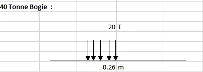
| Pressure on top slab : | ||
| (i) Maximum moment case : |
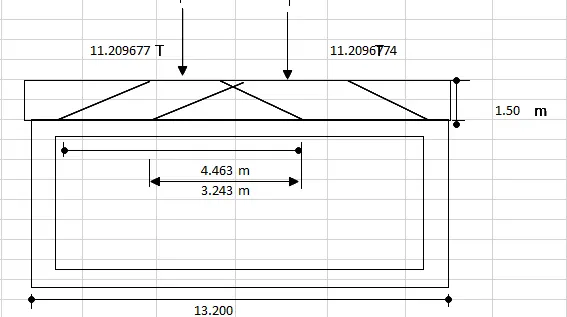
| 40 T load is dispersed with overlappings in both the directions | |||||||
| UDL due to live load | = | 0.917 | T/m2 | ||||
| longitudinal dispersion | = | 5.683 | m | ||||
| transverse dispersion | = | 8.603 | m | ||||
| (ii) Maximum vertical load on wall : |
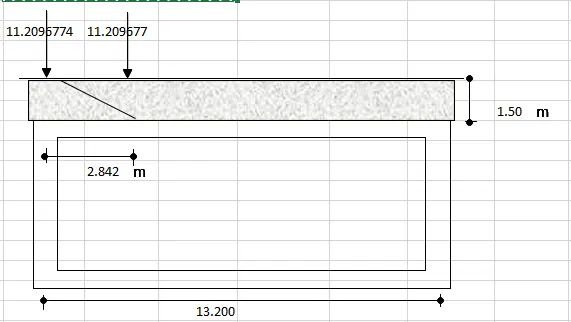
| UDL due to live load | = | 1.376 | T/m2 | ||||
| Dispersion length of live load in longitudinal direction | = | 2.842 | m | ||||
| transverse dispersion | = | 5.73 | m | ||||
| For 70R - Tracked | ||||||||
| Impact factors | ||||||||
| Impact factor = | 10.00% | |||||||
| Effective Dispersion Width | ||||||||
| Dispersion of loads through fills and wearing coat (at 45° angle): | ||||||||
| beff | = | b + 2 * (wc + D + s) | ||||||
| b | = | tyre width along traffic flow | = | 4.57 | m | |||
| wc | = | wearing coat | = | 0 | m | |||
| D | = | Overall depth of slab | = | 0.600 | m | |||
| s | = | thickness of soil above box | = | 1.5 | m | |||
| Hence, dispersion width | = | 8.77 | m | Along the span | ||||
| Calculation of effective width: | ||||||||
| beff = | k * x (1 - x/lo) + b1 | |||||||
| k = | constant depending on b/lo | = | 2.234 | (for b/lo = | 0.99 ) | |||
| lo = | effective span | = | 12.60 | m | ||||
| x = | Distance of centre of gravity from nearest support | = | 2.285 | m | ||||
| x = | Distance of centre of gravity from nearest support | = | 1.1425 | m | ||||
| b = | tyre width along traffic flow | = | 0.84 | m | ||||
| wc = | wearing coat | = | 0 | m | ||||
| b1 = | width of tyre + 2 x thickness of w.c. | = | 3.84 | m | ||||
| Hence, beff for max moment case | = | 8.018 | m | |||||
| Hence, beff for max vertical load case | = | 6.1605 | m | |||||
| Max bending moment in span due to moving udl will occur when udl occupies full span | ||||||||
| Max bending moment in span due to moving conc load will occur under conc load which is near to cg of load system | ||||||||
| when the centre of span is midway between the cg of load system and the conc. load under consideration. | ||||||||
| Maximum axial load in abutment will occur when c.g of heavy loads is near the abutment. | ||||||||
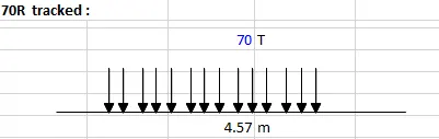
| Pressure on top slab : | ||
| (i) Maximum moment case : |
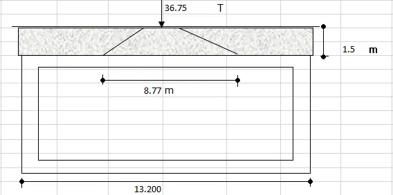
| UDL due to live load | = | 1.153 | T/m2 | ||||
| Dispersion length of live load in the longitudinal direction | = | 8.77 | m | ||||
| transverse dispersion | = | 7.27 | m | ||||
| (ii) Maximum vertical load on wall : |
| UDL due to live load = | 1.738 | T/m2 | |||||
| Dispersion length of live load in the longitudinal direction | = | 6.67 | m | ||||
| transverse dispersion | = | 6.34 | m | ||||
| For CL-A wheeled | 3 Lanes of CL-A | |||||||
| Impact factors | ||||||||
| Impact factor = | 24.19% | |||||||
| Effective Dispersion Width | ||||||||
| Dispersion of loads through fills and wearing coat (at 45° angle): | ||||||||
| beff | = | b + 2 * (wc + D + s) | ||||||
| b | = | tyre width along traffic flow | = | 0.25 | m | |||
| wc | = | wearing coat | = | 0 | m | |||
| D | = | Overall depth of slab | = | 0.600 | m | |||
| s | = | thickness of soil above box | = | 1.5 | m | |||
| Hence, dispersion width | = | 4.45 | m | Along the span | ||||
| Calculation of effective width: | ||||||||
| beff = | k * x (1 - x/lo) + b1 | |||||||
| k = | constant depending on b/lo | = | 2.234 | (for b/lo = | 0.99 ) | |||
| lo = | effective span | = | 12.60 | m | ||||
| x = | Distance of centre of gravity from nearest support | = | 6.3 | m | ||||
| b = | tyre width along traffic flow | = | 0.50 | m | ||||
| wc = | wearing coat | = | 0 | m | ||||
| b1 = | width of tyre + 2 x thickness of w.c. | = | 3.5 | m | ||||
| Hence, beff for max moment case | = | 10.536 | m | |||||
| Max bending moment in span due to Class A will occur when 11.4 T axle is placed near the mid span | ||||||||
| Max bending moment in span due to moving conc load will occur under conc load which is | ||||||||
| near to cg of load system when the centre of span is midway between the cg of load system | ||||||||
| and the conc load under consideration | ||||||||
| Pressure on top slab : | ||
| (i) Maximum moment case : |
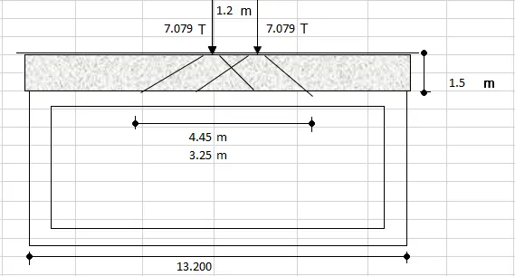
| UDL due to live load | = | 1.083 | T/m2 | ||||
| Dispersion length of live load in the longitudinal direction | = | 5.65 | m | ||||
| transverse dispersion | = | 12.500 | m | ||||
| 70R + Class A: | |||||||||
| Impact factors | |||||||||
| Impact factor = | 24.19% | ||||||||
| Effective Dispersion Width | |||||||||
| Dispersion of loads through fills and wearing coat (at 45° angle): | |||||||||
| beff | = | b + 2 * (wc + d + s) |
|
||||||
| b | = | tyre width along traffic flow | = | 0.26 | m | ||||
| wc | = | wearing coat | = | 0 | m | ||||
| D | = | Overall depth of slab | = | 0.600 | m | ||||
| s | = | thickness of soil above box | = | 1.5 | m | ||||
| Hence, dispersion width | = | 4.463 | m | Along the span | |||||
| Calculation of effective width: | |||||||||
| beff = | k * x (1 - x/lo) + b1 | ||||||||
| k = | constant depending on b/lo | = | 2.234 | (for b/lo = | 0.99 ) | ||||
| lo = | effective span | = | 12.60 | m | |||||
| x = | Distance of centre of gravity from nearest support | = | 6.3 | m | |||||
| b = | tyre width along traffic flow | = | 0.81 | m | |||||
| wc = | wearing coat | = | 0 | m | |||||
| b1 = | width of tyre + 2 x thickness of w.c. | = | 0.81 | m | |||||
| Hence, beff for max moment case | = | 7.846 | m | ||||||
| Max bending moment in span due to 70R vehicle will occur when 17T (with 1.37m spacing) will occupy the midspan | |||||||||
| Max bending moment in span due to moving conc load will occur under conc load which is near to cg of load system | |||||||||
| when the centre of span is midway between the cg of load system and the conc. load under consideration. | |||||||||
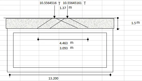
| UDL due to live load | = | 0.871 | T/m2 | ||||
| Dispersion length of live load in the longitudinal direction | = | 5.833 | m | ||||
| transverse dispersion | = | 12.50 | m | ||||
| For Special Vehicle | |||||||||
| Impact factors | |||||||||
| Impact factor = | 0.00% | ||||||||
| Effective Dispersion Width | |||||||||
| Dispersion of loads through fills and wearing coat (at 45° angle): | |||||||||
| beff | = | b + 2 * (wc + d + s) | |||||||
| b | = | tyre width along traffic flow | = | 0.274 | m | ||||
| wc | = | wearing coat | = | 0 | m | ||||
| d | = | effective depth of slab | = | 0.600 | m | ||||
| s | = | thickness of soil above box | = | 1.5 | m | ||||
| Hence, dispersion width | = | 4.474 | m | Along the span | |||||
| Calculation of effective width: | |||||||||
| beff = | k * x (1 - x/lo) + b1 | ||||||||
| k = | constant depending on b/lo | = | 2.233651 | (for b/lo = | 0.992 ) | ||||
| lo = | effective span | = | 12.60 | m | |||||
| x = | Distance of centre of gravity from nearest support | = | 6.3 | m (for max. moment case) | |||||
| x = | Distance of centre of gravity from nearest support | = | 0.75 | m (for max. vertical load case) | |||||
| b = | tyre width across traffic flow | = | 0.156 | m | |||||
| wc = | wearing coat | = | 0 | m | |||||
| b1 = | width of tyre + 2 x thickness of w.c. | = | 3.156 | m | |||||
| Hence, beff for max moment case | = | 10.192 | m | Perpendicular | |||||
| Hence, beff for max vertical load case | = | 4.732 | m | to the span | |||||
| Max bending moment in span due to moving conc load will occur under conc load which is near to cg of load system | |||||||||
| when the centre of span is midway between the cg of load system and the conc. load under consideration. | |||||||||
| Maximum axial load in abutment will occur when c.g of heavy loads is near the WALL | |||||||||
| Pressure on top slab : | ||
| (i) Maximum moment case : |
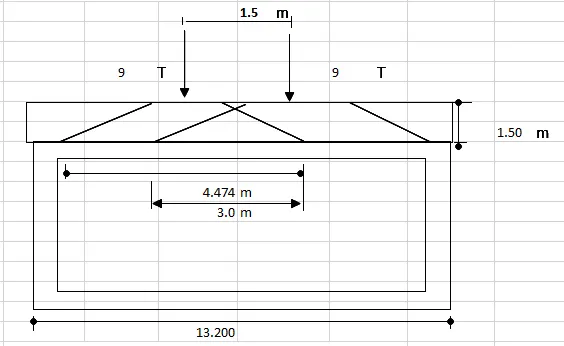
| 40 T load is dispersed with overlappings in both the directions | |||||||
| UDL due to live load | = | 0.744 | T/m2 | ||||
| longitudinal dispersion | = | 5.974 | m | ||||
| transverse dispersion | = | 8.096 | m | ||||
| (ii) Maximum vertical load on wall : |
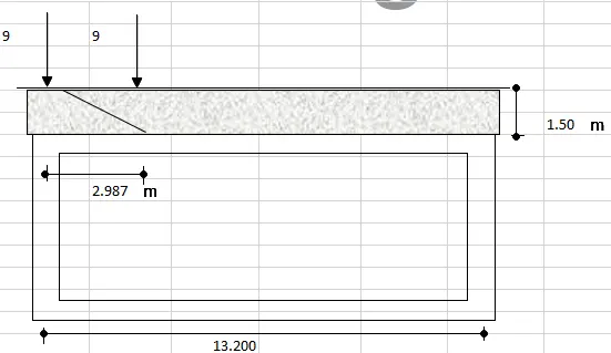
| UDL due to live load | = | 1.123 | T/m2 | ||||
| Dispersion length of live load in longitudinal direction | = | 2.987 | m | ||||
| transverse dispersion | = | 5.37 | m | ||||
| COMPUTATION OF FORCE DUE TO TEMPERATURE GRADIENT: |
| The variation of temperature gradient as follows: |
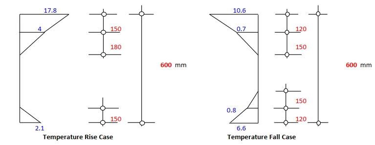
Grade of Concrete = M30
"YOUNG'S MODULUS, E =" 3.10E+06 t/m2
"Coeff. Of Thermal Expansion,a =" 1.20E-05 / oC
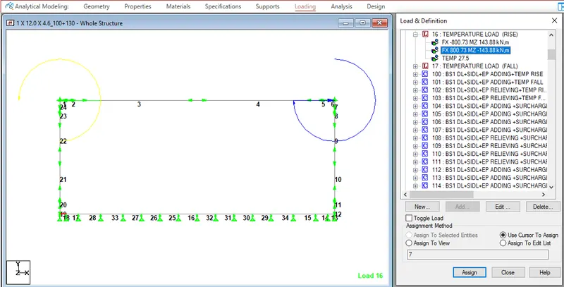
Computation of Forces in Members due to Temperature Rise Case:
Node "1, 2 & 6, 7"
MEMBER 1 & 6
Thickness of member = 600 mm
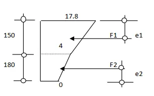
STRESS
17.8 662.2 t/m2
F1 = 60.82 t
150 F1 e1 e1 = 0.059 m
4 148.8 t/m2 F2 = 13.39 t
e2 = 0.120 m
180 F2
e2
0 0.0 t/m2
Net force on member = 74.21 t
Net moment on member = 15.853 tm
Node 3 & 5
MEMBER 2 & 5
Thickness of member = 600 mm
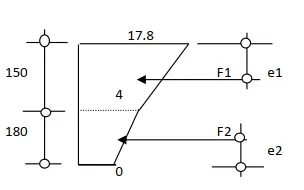
STRESS
17.8 662.2 t/m2
F1 = 60.82 t
150 F1 e1 e1 = 0.0592 m
4 148.8 t/m2 F2 = 13.39 t
e2 = 0.1200 m
180 F2
e2
0 0.0 t/m2
Net force on member = 74.21 t
Net moment on member = 15.853 tm
Node 4
MEMBER 3 & 4
Thickness of member = 600 mm
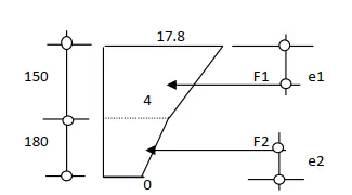
STRESS
17.8 662.2 t/m2
F1 = 60.82 t
150 F1 e1 e1 = 0.0592 m
4 148.8 t/m2 F2 = 13.39 t
e2 = 0.1200 m
180 F2
e2
0 0.0 t/m2
Net force on member = 74.21 t
Net moment on member = 15.853 tm
Node "1, 2 & 6, 7"
MEMBER 1 & 6
Thickness of member = 600 mm
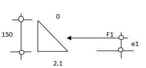
STRESS
0 0.0 t/m2
F1 = 5.86 t
150 F1 e1 = 0.0500 m
e1
2.1 78.1 t/m2
Net force on member = 5.86 t
Net moment on member = 1.465 tm
Node 3 & 5
MEMBER 2 & 5
Thickness of member = 600 mm
STRESS
0 0.0 t/m2
F1 = 5.86 t
150 F1 e1 = 0.0500 m
e1
2.1 78.1 t/m2
Net force on member = 5.86 t
Net moment on member = 1.465 tm
Node 4
MEMBER 3 & 4
Thickness of member = 600 mm
STRESS
0 0.0 t/m2
F1 = 5.86 t
150 F1 e1 = 0.0500 m
e1
2.1 78.1 t/m2
Net force on member = 5.86 t
Net moment on member = 1.465 tm
Computation of Forces in Members due to Temperature Fall Case:
Node "1, 2 & 6, 7"
MEMBER 1 & 6
Thickness of member = 600 mm
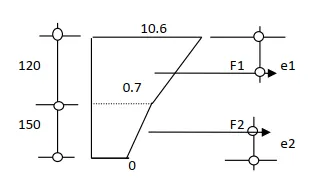
STRESS
10.6 394.3 t/m2
F1 = 25.22 t
120 F1 e1 e1 = 0.0425 m
0.7 26.0 t/m2 F2 = 1.95 t
e2 = 0.1000 m
150 F2
e2
0 0.0 t/m2
Net force on member = 27.17 t
Net moment on member = 6.749 tm
Node 3 & 5
MEMBER 2 & 5
Thickness of member = 600 mm
STRESS
10.6 394.3 t/m2
F1 = 25.22 t
120 F1 e1 e1 = 0.0425 m
0.7 26.0 t/m2 F2 = 1.95 t
e2 = 0.1000 m
150 F2
e2
0 0.0 t/m2
Net force on member = 27.17 t
Net moment on member = 6.749 tm
Node 4
MEMBER 3 & 4
Thickness of member = 600 mm
STRESS
10.6 394.3 t/m2
F1 = 25.22 t
120 F1 e1 e1 = 0.0425 m
0.7 26.0 t/m2 F2 = 1.95 t
e2 = 0.1000 m
150 F2
e2
0 0.0 t/m2
Net force on member = 27.17 t
Net moment on member = 6.749 tm
Node "1, 2 & 6, 7"
MEMBER 1 & 6
Thickness of member = 600 mm
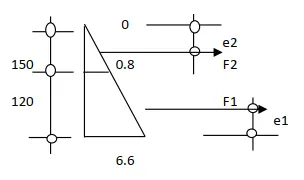
STRESS
0 0.0 t/m2
e2
150 0.8 F2 29.8 t/m2
F1 = 16.52 t
120 F1 e1 = 0.0443 m
e1 F2 = 2.23 t
e2 = 0.1000 m
6.6 245.5 t/m2
Net force on member = 18.75 t
Net moment on member = 4.513 tm
Node 3 & 5
MEMBER 2 & 5
Thickness of member = 600 mm
STRESS
0 0.0 t/m2
e2
150 0.8 F2 29.8 t/m2
F1 = 16.52 t
120 F1 e1 = 0.0443 m
e1 F2 = 2.23 t
e2 = 0.1000 m
6.6 245.5 t/m2
Net force on member = 18.75 t
Net moment on member = 4.513 tm
Node 4
MEMBER 3 & 4
Thickness of member = 600 mm
STRESS
0 0.0 t/m2
e2
150 0.8 F2 29.8 t/m2
F1 = 16.52 t
120 F1 e1 = 0.0443 m
e1 F2 = 2.23 t
e2 = 0.1000 m
6.6 245.5 t/m2
Net force on member = 18.75 t
Net moment on member = 4.513 tm
| Summary of Bending Moments and Shear Forces |
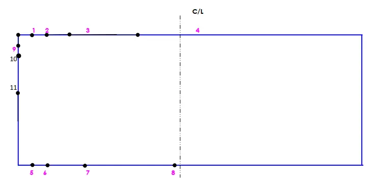
| ULS | ||||||
| BOTTOM SLAB (LOAD COMB 100 - 235) | ||||||
| TOP SLAB & WALLS (LOAD COMB 282 - 348) | ||||||
| Node.No | Element | Location | Bending moment (LHS) | Bending moment (RHS) | Shear Force (LHS) | Shear Force (RHS) |
| 5 | Bottom Slab | Support | 477.242 | 315.378 | ||
| 6 | deff | 418.267 | 357.266 | |||
| 7 | Curtailment | 271.216 | 343.537 | 186.671 | 250.737 | |
| 8 | Midspan | 427.459 | 224.817 | |||
| SLS (LOAD COMB 236-271) | ||||
| Node.No | Element | Location | Bending moment | Bending moment |
| 5 | Bottom Slab | Support | 321.027 | 216.16 |
| 7 | Curtailment | 66.121 | 235.938 | |
| 8 | Midspan | 302.26 | ||
| QUASI (LOAD COMB 272-281) | ||||
| Node.No | Element | Location | Bending moment | Bending moment |
| 5 | Bottom Slab | Support | 197.619 | 197.612 |
| 7 | Curtailment | 52.363 | 133.874 | |
| 8 | Midspan | 225.036 | ||
| Check for Flexure | |||||||||||||
| Design of Different Sections by ULS Method: | |||||||||||||
| Concrete Grade = | M30 | Steel Grade = | Fe500 | fcd = | 13.4 | ||||||||
| Clear cover to r/f = | 45mm | For walls & Top slab | Allowable Crack Width = | 0.3 | mm | fywd = | 348 | ||||||
| 75mm | Bottom slab | fctm = | 2.5 | Mpa | |||||||||
| fyk= | 500 | Mpa | |||||||||||
| SL. NO |
DESCRIPTION | Units | Bottom Slab | |||
| Support | at Curtailment section | Midspan | ||||
| 1 | Design Moments | tm | 47.7 | 34.4 | 22.5 | |
| 2 | Design Shear Forces | 41.8 | 25.1 | 0.0 | ||
| 2 | Design Shear Forces | t | 41.8 | 25.1 | 0.0 | |
| 3 | Overall width provided | mm | 1000 | 1000 | 1000 | |
| 4 | Overall depth provided | mm | 650 | 650 | 650 | |
| 5 | Check for Flexure | |||||
| Effective cover provided | mm | 88 | 85 | 85 | ||
| Effective depth provided, d | mm | 563 | 565 | 565 | ||
| MR from concrete =0.133*fck*b*d2 | Nmm | 1.26E+09 | 1.27E+09 | 1.27E+09 | ||
| Provided Ast for "+" BM | mm2 | 3460 | 1571 | 3142 | ||
| Minimum Reinforcement = 0.13%btd or 0.26*(fctm/fyk)*btd | mm2 | 731 | 735 | 735 | ||
| Status of Section | OK | OK | OK | |||
| Lever arm, z =({1-0.974*fy*As/(fck*b*d)} | mm | 506 | 540 | 514 | ||
| MR of steel =0.87*fy*As*z= | Nmm | 7.62E+08 | 3.69E+08 | 7.02E+08 | ||
| Moment of Resistance of Section | tm | 76.2 | 36.9 | 70.2 | ||
| Status of Section | OK | OK | OK | |||
| 6 | Provision of Reinforcement | |||||
| Bottom Slab | ||||||
| Support | Midspan | |||||
| Provided Reinforcement |
Spacing | 200 | 200 | 200 | ||
| Dia | 16 | 20 | 20 | |||
| Spacing | 200 | 200 | 200 | |||
| Dia | 25 | 0 | 20 | |||
| Spacing | 0 | 0 | 0 | |||
| Dia | 0 | 0 | 0 | |||
| Neutral axix Depth | 84.18 | 59.20 | 74.50 | |||
| M/(bd2Fav) = kav | 0.14 | 0.10 | 0.12 | |||
| Required reinforcement As | 2075.65 | 1459.65 | 1836.99 | |||
| Distribution Reinforcement = 20% of Main Reinforcement to be provided on both faces | =20% of Ast | 415 | 292 | 367 | ||
| Max reqd | 415 | 292 | 367 | |||
| Provided | 646 | 646 | 646 | |||
| Top face | Spacing | 175 | 175 | 175 | ||
| Dia | 12 | 12 | 12 | |||
| Bottom face | Spacing | 175 | 175 | 175 | ||
| Dia | 12 | 12 | 12 | |||
| OK | OK | OK | ||||
| Check for Shear | |||||||
| Support | at Curtailment section | Midspan | |||||
| Ult. Applied Shear Force, Vult | KN | 418 | 251 | 0 | |||
| Overall Width, bw | m | 1.000 | 1.000 | 1.000 | |||
| Overall Depth, h | m | 0.650 | 0.650 | 0.650 | |||
| v =0.6[1-(fck/310)] | 0.542 | 0.542 | 0.542 | ||||
| Max Shear Check VEd <=0.5bw d v fcd | KN | 2042 | 2051 | 2051 | |||
| OK | OK | OK | |||||
| Area of Section | m2 | 0.650 | 0.650 | 0.650 | |||
| Horizontal Force | KN | 167.9 | 0.0 | 0.0 | |||
| Cg of steel | m | 0.088 | 0.085 | 0.085 | |||
| Comp. Stress due to Horizontal force, scp | Mpa | 0.258 | 0.000 | 0.000 | |||
| VRd.c = | [0.12K(80r1.fck)0.33+0.15scp]bw.d | ||||||
| Overall Width, bw | m | 1.000 | 1.000 | 1.000 | |||
| z = (D - Yord) | m | 0.563 | 0.565 | 0.565 | |||
|
1.60 | 1.59 | 1.59 | ||||
| r1 | 0.006 | 0.003 | 0.006 | ||||
| vmin = 0.031 K 3/2 fck 1/2 | Mpa | 0.342 | 0.342 | 0.342 | |||
| VRd.c = | KN | 284 | 202 | 254 | |||
| vRd.c min =(vmin + 0.15scp)bw.d | KN | 214 | 193 | 193 | |||
| Govering VRdc= | KN | 284 | 202 | 254 | |||
| Design Shear Capacity, Vc | KN | 284 | 202 | 254 | |||
| Provision of Shear Reinforcement (Cl. 10.3.3.2 of IRC 112-2011) | |||||||
| Ultimate Applied Shear, Vuapplied | kN | 418 | 251 | 0 | |||
| av | mm | 563 | 565 | 565 | |||
| b | = av/2d | 1 | 1 | 1 | |||
| Vu | kN | 418 | 251 | 0 | |||
| Design Shear Capacity, Vc | kN | 284 | 202 | 254 | |||
| Reqirement of shear reinforcement | YES | YES | NO | ||||
| acw | 1.009 | 2.500 | 2.500 | ||||
| n1 | 0.600 | 0.600 | 0.600 | ||||
| Maximum allowable shear stess (q = 45) | Mpa | 3.658 | 3.658 | 3.658 | |||
| Allowable shear stress ( q = 21.8) | Mpa | 2.52 | 2.52 | 2.520 | |||
| actual Shear stress | Mpa | 0.8262 | 0.4931 | 0.000 | |||
| Since the actual shear stress is less than allowable shear stress with q of 21.8 degrees, q is limited to 21.8 degrees | |||||||
| i) Aswmax / S = 0.5*bw*acw*n1*fcd/(fywd) | mm2/m | 11657.020 | 28893.750 | 28893.750 | |||
| ii) 0.072 x (SQRT(fck))/fyk | mm2/m | 788.720 | 788.720 | 788.720 | |||
| Shear reinforcement required Asv/Sv = (Vu)/(z*fywd) cotq | mm2/m | 1068.828 | 637.892 | 0.000 | |||
| spacing of 5L-8mm S-links | mm | 235.143 | 318.652 | 509.838 | |||
| Spacing along the span of the box | mm | 200.0 | 200.0 | 307.000 | |||
| Check for Stresses | |||||||||||
| Concrete Grade = | 30.00 | Steel Grade | = | Fe500 | |||||||
| Clear cover to r/f = | 45mm | For walls & Top slab | Elasticity modulus of Concrete | = | 31000 | Mpa | |||||
| Clear cover to r/f = | 75mm | Bottom slab | |||||||||
| sst | = | 300.000 | Mpa | ||||||||
| sck | = | 14.40 | Mpa | ||||||||
| m | = | 6.48 | |||||||||
Bottom Slab
| SL. NO |
DESCRIPTION | Units | |||
| at Curtailment section | Midspan | ||||
| 1 | Design "+" Moments | tm | 6.6 | 29.1 | |
| 2 | Overall width provided | mm | 1000 | 1000 | |
| 3 | Overall depth provided | mm | 650 | 650 | |
| 4 | Modulur ratio, m | mm | 6.48 | 6.48 | |
| 5 | Check for Flexure | ||||
| Steel percentage (p) | mm | 0.28 | 0.56 | ||
| Depth of neutral axis | mm | 97 | 133 | ||
| Lever arm factor | 530 | 521 | |||
| Effective cover provided | mm | 85 | 85 | ||
| Effective depth provided, d | mm | 563 | 565 | ||
| Provided Ast for "+" BM | mm2 | 1571 | 3142 | ||
| Stress in concrete | N/mm2 | 2.6 | 8.4 | ||
| Stress in reinforcement | N/mm2 | 79.4 | 177.9 | ||
| Status of Section | OK | OK | |||
| Check for Crack width | Units | @ curtailment sections | Midspan | ||
| Design Moments | tm | 5.2 | 22.50 | ||
| Area of reinforcement | mm2 | 1571 | 3142 | ||
| Lever arm | mm | 530 | 521 | ||
| Depth of Neutral Axis | mm | 97 | 133 | ||
| Stress in concrete | N/mm2 | 2.0 | 6.5 | ||
| Stress in reinforcement | N/mm2 | 62.9 | 137.5 | ||
| Average Strain at the level, em | 3.14E-04 | 6.88E-04 | |||
| Diameter check (As per cl.12.3.6 IRC:112-2011) | OK | OK | |||
| Spacing check (As per cl.12.3.6 IRC:112-2011) | OK | OK | |||
| Crackwidth at mid point between two bars | |||||
| Crackwidth Wk = Sr,max*(εsm - εcm) | |||||
| Provided spacing of tensile reinforcement | mm | 100 | 100 | ||
| Φeq | mm | 20 | 20 | ||
| hc,eff | mm | 184 | 172 | ||
| ρp,eff | 0.0085 | 0.0182 | |||
| Sr,max | mm | 688 | 476 | ||
| kt | 0.5 | 0.5 | |||
| fct,eff | Mpa | 2.5 | 2.5 | ||
| αe | 6.45 | 6.45 | |||
| Es | Mpa | 2.00E+05 | 2.00E+05 | ||
| σsc | Mpa | 62.9 | 137.5 | ||
| εsm - εcm = (σsc - (kt*fct,eff/ρp,eff)*(1+αe*ρp,eff))/Es | 0.0002 | 0.0004 | |||
| Wk = Sr,max*(εsm - εcm) | mm | 0.130 | 0.196 | ||
| Allowable crack width | mm | 0.3 | 0.3 | ||
| Status of sections | OK | OK | |||
Reinforcement Detailing:-