Project 1
Project 01 - Wiring harness routing of Engine V16
Procedure followed to prepare the wiring harness, flattening and drawing of the harness bundle product :-
As an AI language model, I can provide you with a general outline of the process you described. However, it's important to note that the specific details and steps may vary depending on the CAD software you're using and the requirements of your project. Here's a high-level overview of how you might approach this task:
1. Define Connectors Electrically:
Identify all the connectors required for the electrical system.
Define the electrical characteristics of each connector, including pin configuration, voltage ratings, current ratings, etc.
2. Place Connectors on Engine 3D CAD Model:
Open the Engine 3D CAD model in your CAD software.
Position the connectors at their required locations on the engine, ensuring proper alignment and clearance.
3. Install P-clamps and Fir Tree Clips:
Determine the packaging rules for installing P-clam
ps and Fir Tree clips.
Place P-clamps and Fir Tree clips at appropriate positions along the wiring harness route, ensuring secure attachment without interfering with other components.
4. Create Wiring Harness Routing:
Begin routing the wiring harness by connecting the defined connectors.
Follow packaging rules and design guidelines to route the harness efficiently and neatly.
Create branching points as needed to accommodate sub-branches and connect to various connectors.
5.Apply Protection Coverings:
Identify areas of the wiring harness that require protection coverings, such as heat shields, abrasion-resistant sleeves, or conduit.
Apply protection coverings to safeguard the wiring harness from environmental factors and mechanical damage.
6.Flatten Wiring Harness:
Utilize the CAD software's tools to flatten the wiring harness into a 2D representation.
Ensure that the flattened harness maintains proper wire lengths and routing.
7. Create Drawing Sheet with Flattened Wiring Harness:
Use the Drafting Workbench in your CAD software to create a drawing sheet.
Include the flattened wiring harness layout on the drawing sheet, along with any necessary annotations, dimensions, and labels.
STEPS INVOVLVED IN CREATION OF HARNESS MODEL
Download the given engine Cad file contain the v16 engine model
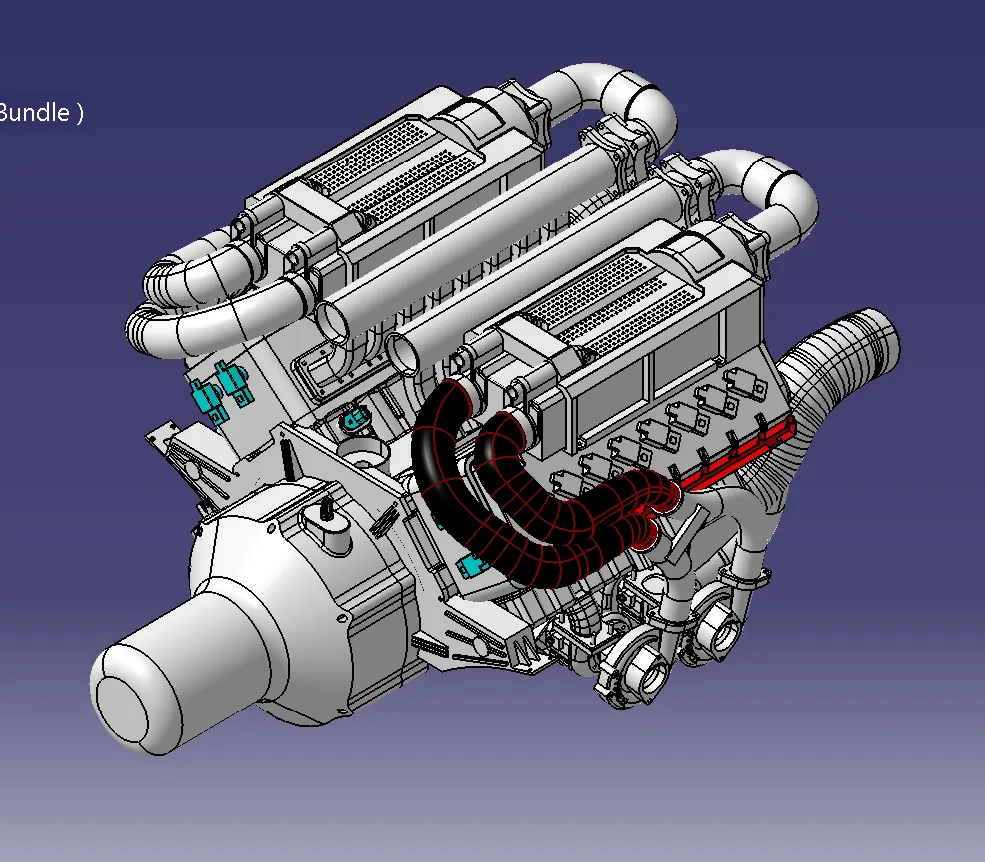
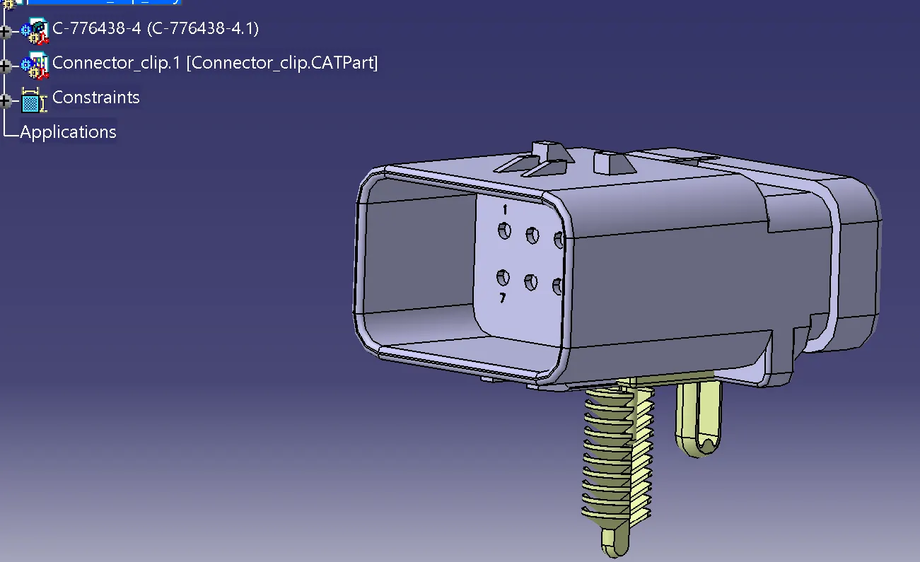
Now, download the required Connectors from the Source and Convert the Mechanical Connectors electrically by using the electrical part design work bench
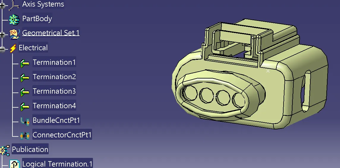
4 Pole connector used in injectors and with sevrel sensors like cam sensor cranck sensor
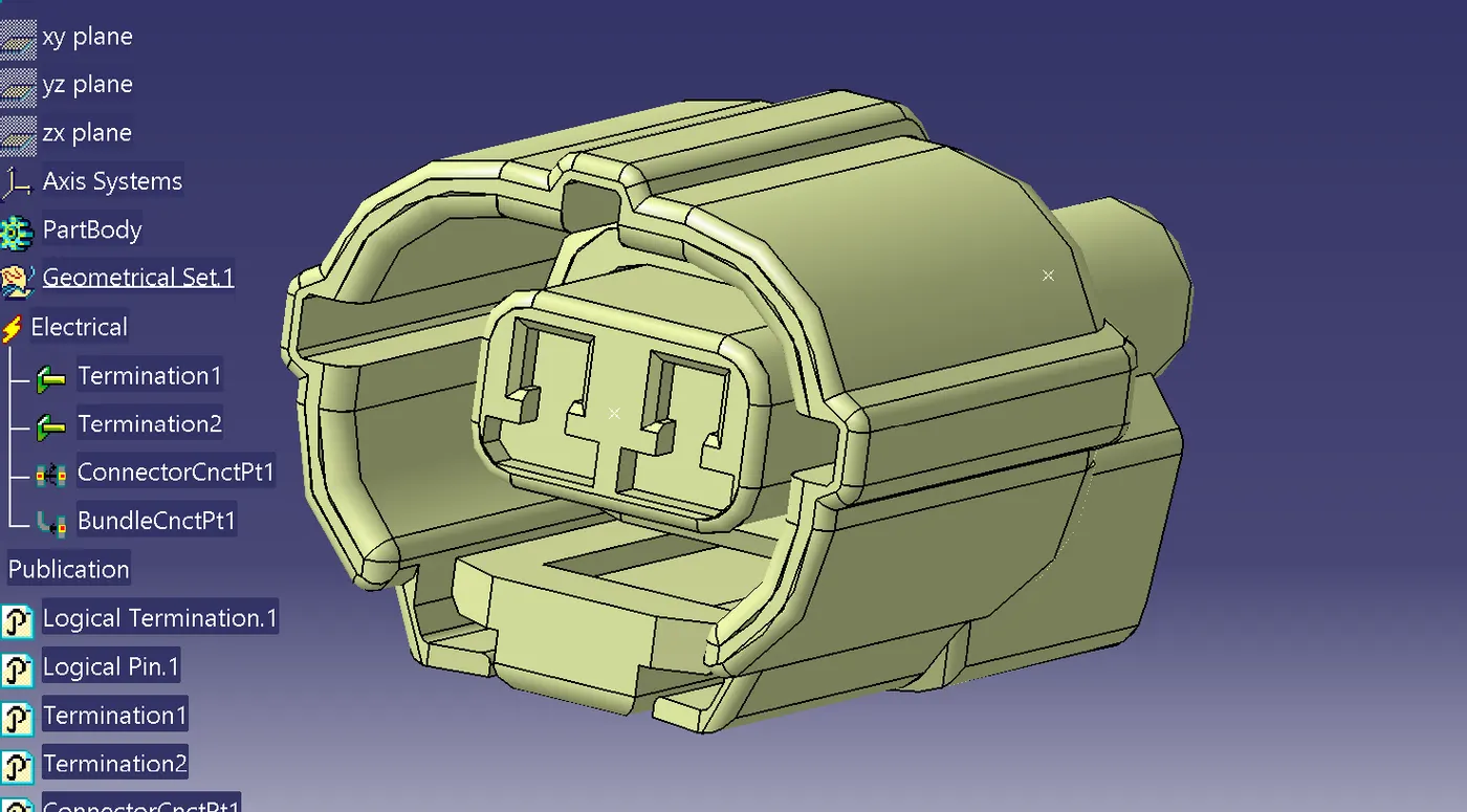
2 pole connectors used for sensors
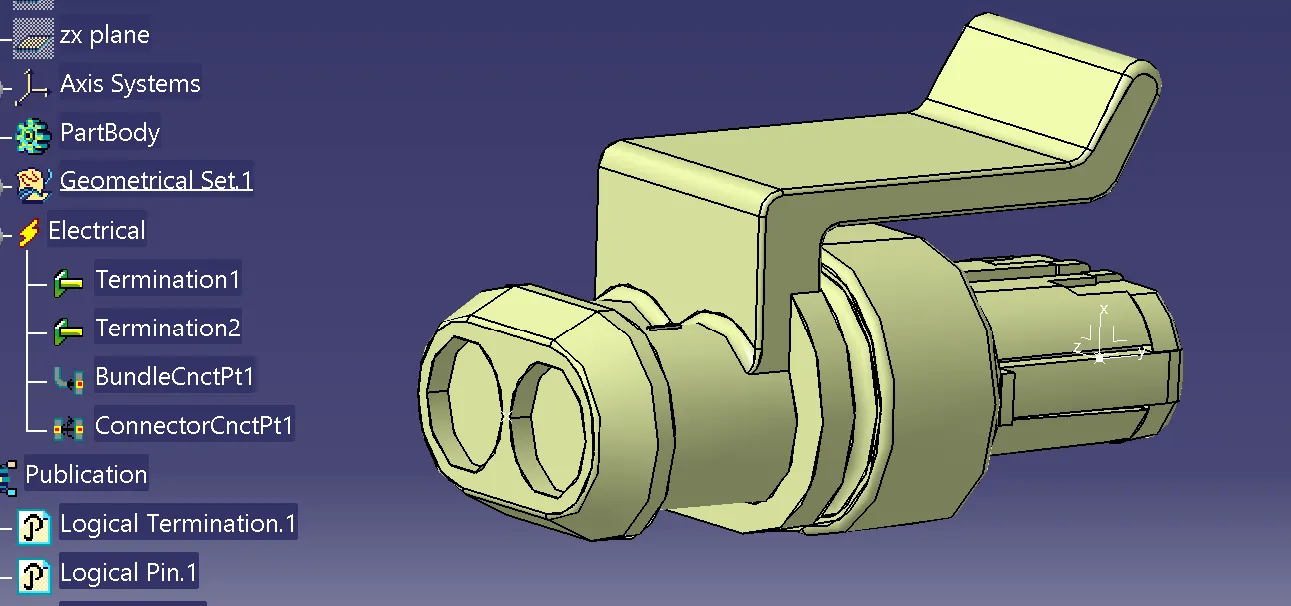
12 pole connector fixed with clip
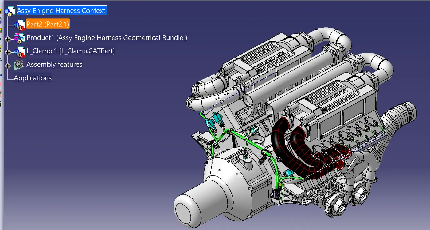
Creating the Context assembly :-
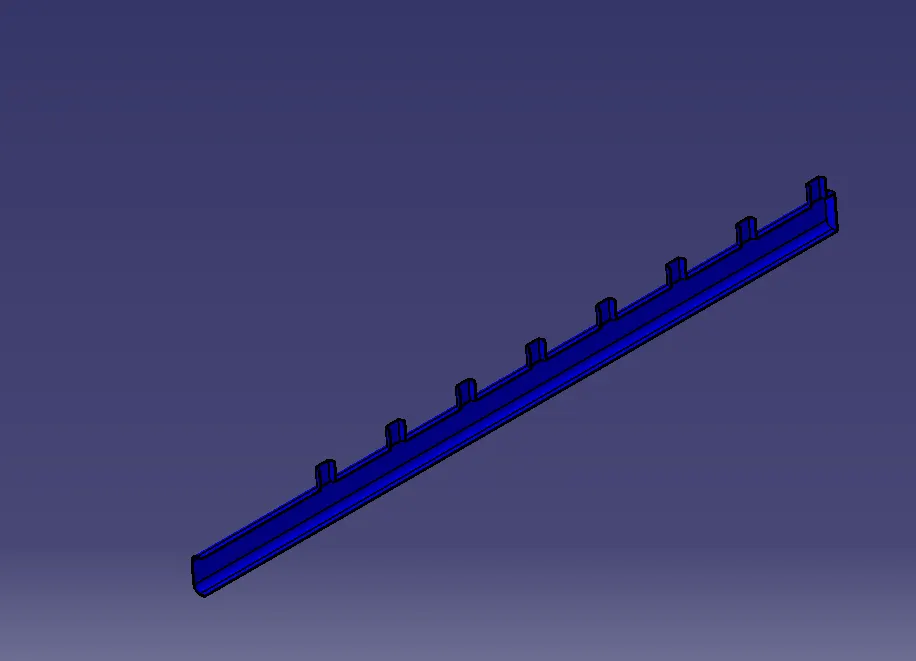
lastic channel :- Use of guiding channel at the entire of bundle to injectors for protect the wiring harness from the high temperature.
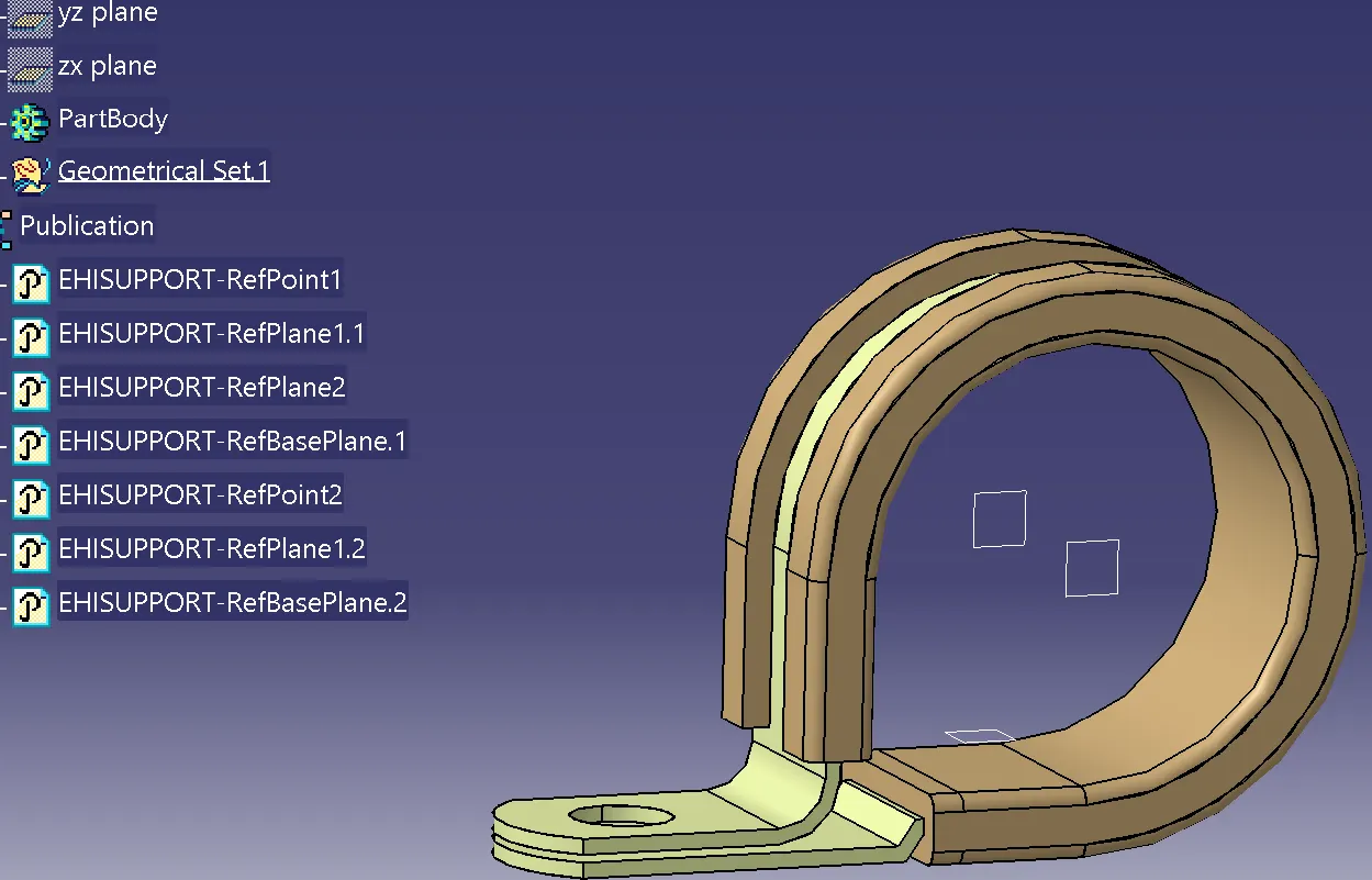
Clamps And Clips:- we have to mount 3 P-clamps also on the existing bolts of the engine so before that we have to define P-clamp electrically with geometrical parameters, entry and exit point on both left and right side of the P-clamp as shown in below figure.
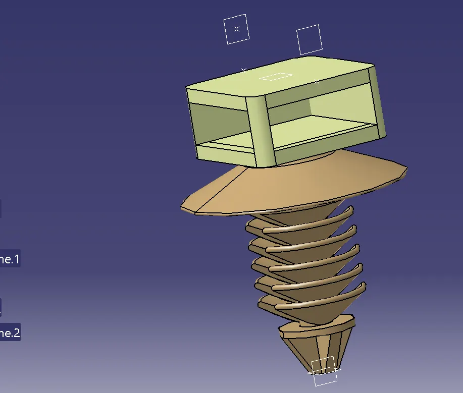
Furr tree clips are used to avoid to the fouling pf the harness into the engine partbody as well as provide good fitment with along with desired geometry . The clip aslo defined electrically similarly as clamps using electric part design workbench.
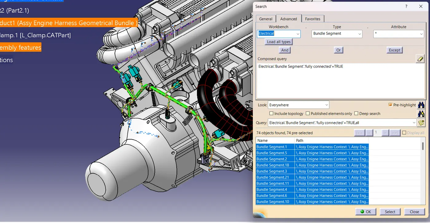
Electrical Continuity check :- Connectivity analysis result shown below
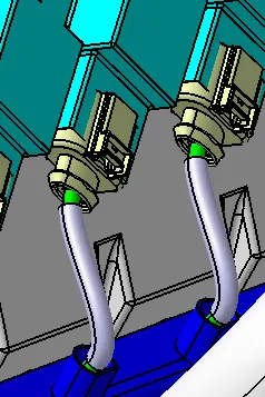
Add Protective Coverings:- Add COT tubes and cotton tapne of 20mm and 7mm to avoide harness from physical damage and can not affected by the high temp. We use cotton tape at the high temp. zone of engine which is injector sensor area where entire of bundle in the injector sensor taken place
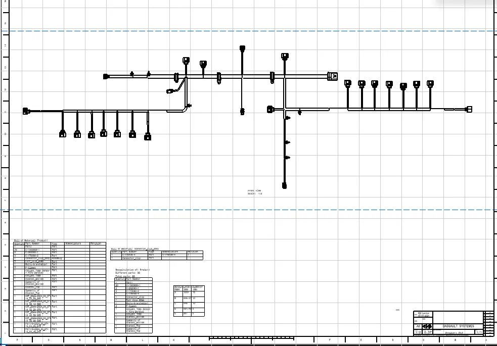
Flattening the Wiring Harness Routed:- Using Flattening workbench we have flattened the geometry and adjust the view to create drawing.
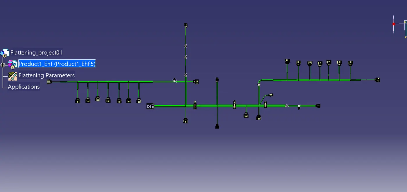
Create the drawing of routed harness:- Create a new drawing file in the drafting Workbench. Insert the flattened harness product into the drawing sheet using view option and selecting the front view command.
NOTE : All Files are attached
filename " Assy Engine Harness Context" is a context engine assembly file
filename "flattening_project01" is a flattened file of the harness
fiename "project01_Drawing " is drawing of flattenend view
Drive link:-
https://drive.google.com/file/d/1c2AKzyIkPJuYW-YZrZkRooGrltM-Itwo/view?usp=drive_link