Project 1

Buck converter:
It is part of dc-to-dc converter use for step down the voltage. A Buck converter steps down a DC voltage from the input to the output. The circuit operation depends on the conduction state of the MOSFET: On-state: The current through the inductor increases and the diode blocks.
The buck converter is so named because the inductor always “bucks” or acts against the input voltage. The output voltage of an ideal buck converter is equal to the product of the switching duty cycle and the supply voltage.
CCM:
Buck Converter Continuous conduction mode (CCM) was analysed in continuous conduction mode (CCM), i.e., the inductor current was always greater than 0.
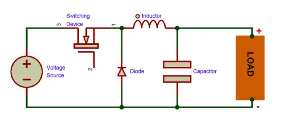
Given data for design the buck converter:
Vout = 30v
Vin = 40-50v (we select 50v)
Power (P) = 500w
Switching frequency assume = 50khz
Now calculate:
Duty cycle (D):
D = Vout/Vin
= 30/50
=0.6
Resistance value (R):
R = Vout^2/P
= 30x30/500
= 1.8ohm
Inductor current:
I = P/Vout
= 500/30
= 16.67amp
Inductor current ripple is < 10%
∆IL = 0.1 X 16.67
= 1.67 amp
Inductor value (L):
L = (Vout / fs*∆IL) *(1-D)
= (30/50x1000x1.67)*(1-0.6)
=0.1437mH
Capacitor value (Cout):
Cout= (1-D) / 8*L*fs^2*(∆V0/V)
=(1-0.6) / 8*0.1437mH*(50k)^2*(0.01)
=0.4 / 28740
= 13.9179µF
Capacitor such that the output voltage ripple is < 10%.
Now we are find out the parameter:
|
Parameter |
Value |
|
Output voltage Vout |
30v |
|
Input voltage Vin |
50v |
|
Output current I |
16.67Amp |
|
Duty cycle D |
60% |
|
Resistance R |
1.8Ω |
|
Inductor L |
0.1437mH |
|
Capacitor C |
13.9179µf |
|
Ripple current ∆IL |
1.67amp |
|
Power P |
500w |
|
Switching frequency (Assume) fs |
50Khz |
|
inductor current ripple |
<10% |
|
capacitor output voltage ripple |
<10% |
Parameters setting:
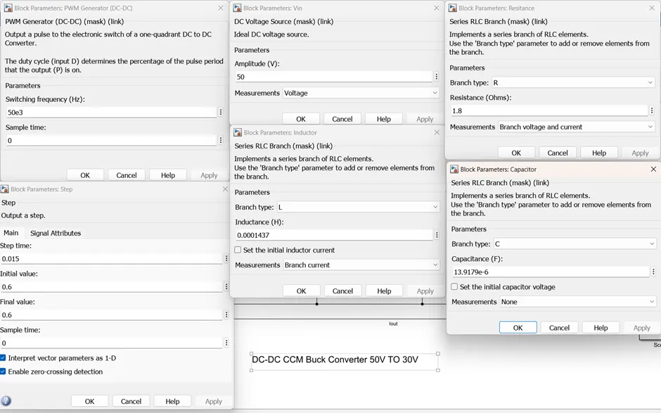
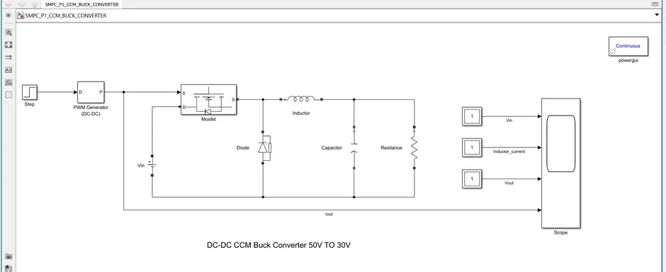
Model:
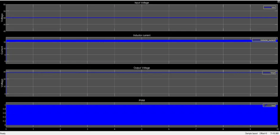
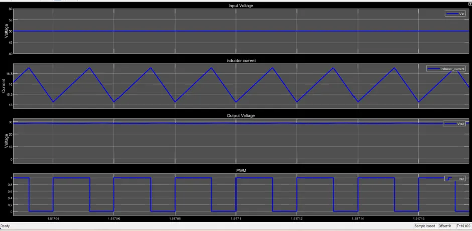
Output:

Given data for design the buck converter:
Vout = 300v
Vin = 400-500v (we select 500v)
Power (P) = 5kw
Switching frequency assume = 50khz
Now calculate:
Duty cycle (D):
D = Vout/Vin
= 300/500
=0.6
Resistance value (R):
R = Vout^2/P
= 300x300/5000
= 18ohm
Inductor current:
I = P/Vout
= 5000/300
= 16.67amp
Inductor current ripple is < 10%
∆IL = 0.1 X 16.67
= 1.67 amp
Inductor value (L):
L = (Vout / fs*∆IL) *(1-D)
= (300/50x1000x1.67)*(1-0.6)
=1.4371mH
Capacitor value (Cout):
Cout= (1-D) / 8*L*fs^2*(∆V0/V)
=(1-0.6) / 8*1.437mH*(50k)^2*(0.01)
=0.4 / 28740
= 1.39179µF
Capacitor such that the output voltage ripple is < 10%.
Now we are find out the parameter:
|
Parameter |
Value |
|
Output voltage Vout |
300v |
|
Input voltage Vin |
500v |
|
Output current I |
16.67Amp |
|
Duty cycle D |
60% |
|
Resistance R |
18Ω |
|
Inductor L |
1.4371mH |
|
Capacitor C |
1.39179µf |
|
Ripple current ∆IL |
1.67amp |
|
Power P |
5kw |
|
Switching frequency (Assume) fs |
50Khz |
|
inductor current ripple |
<10% |
|
capacitor output voltage ripple |
<10% |
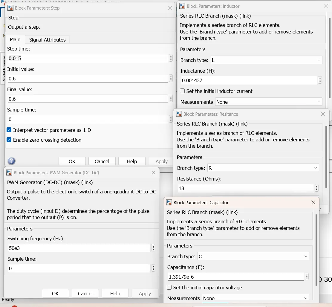
Parameters:
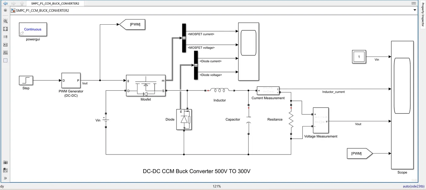
Model:
Current & voltage of Mosfet & diode
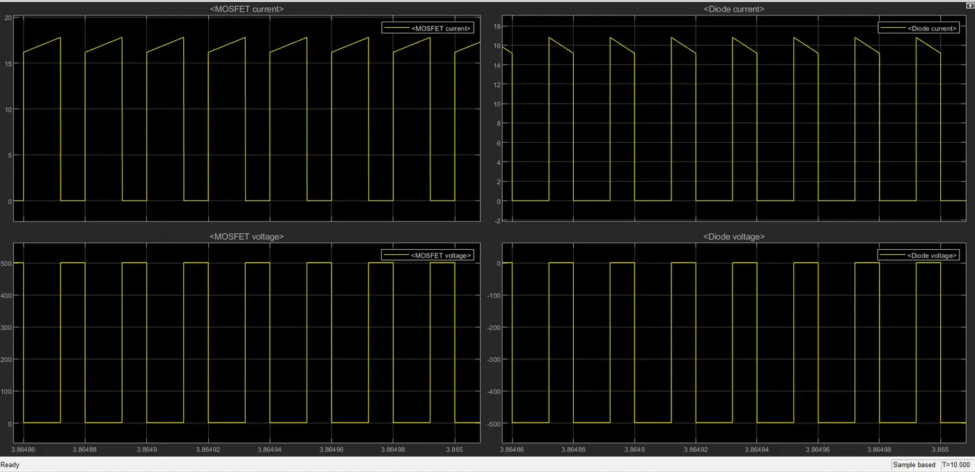
Output:
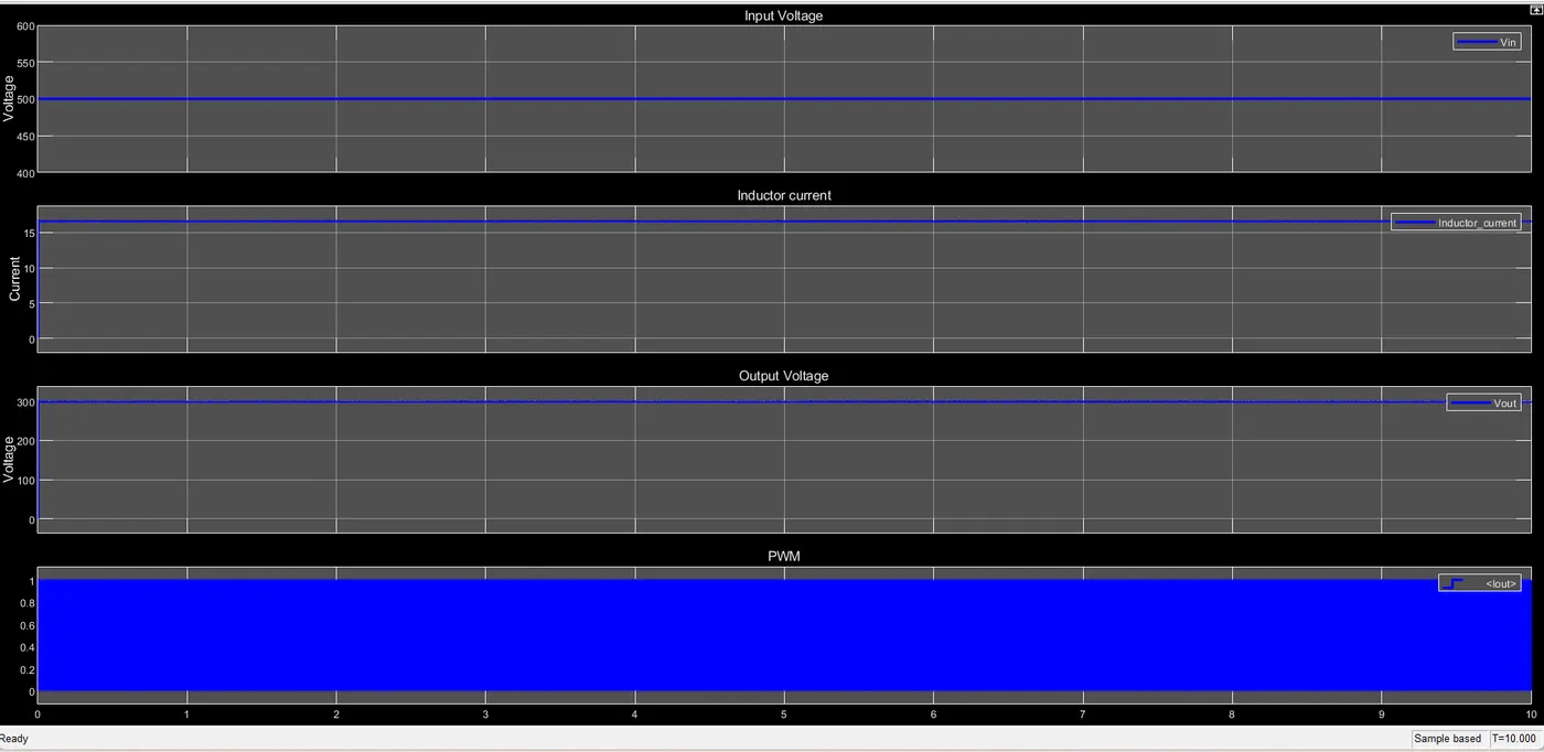
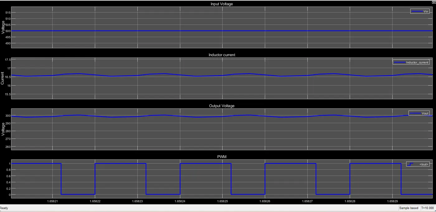

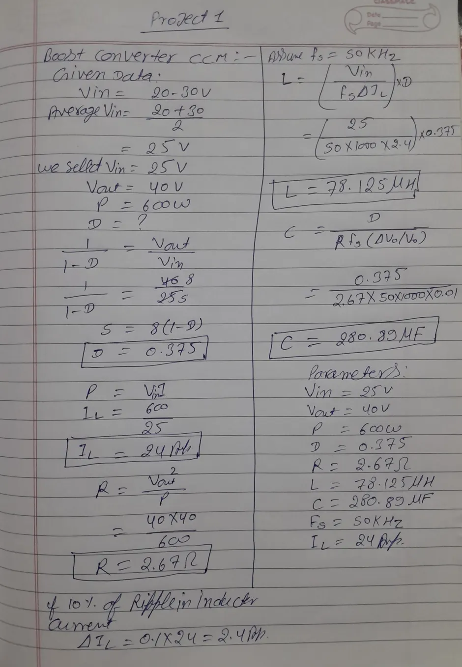
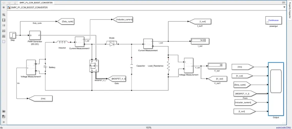
Parameters:
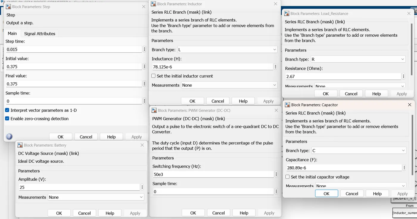
Model:
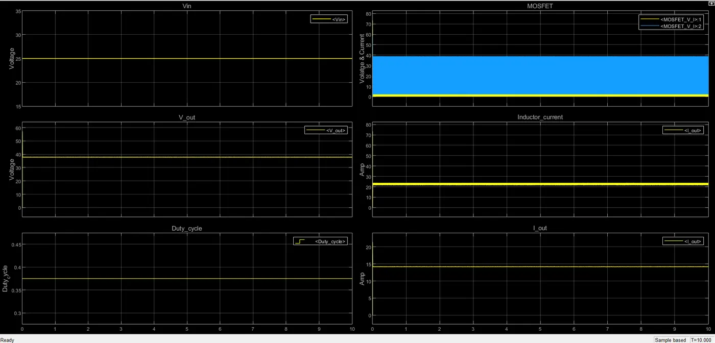
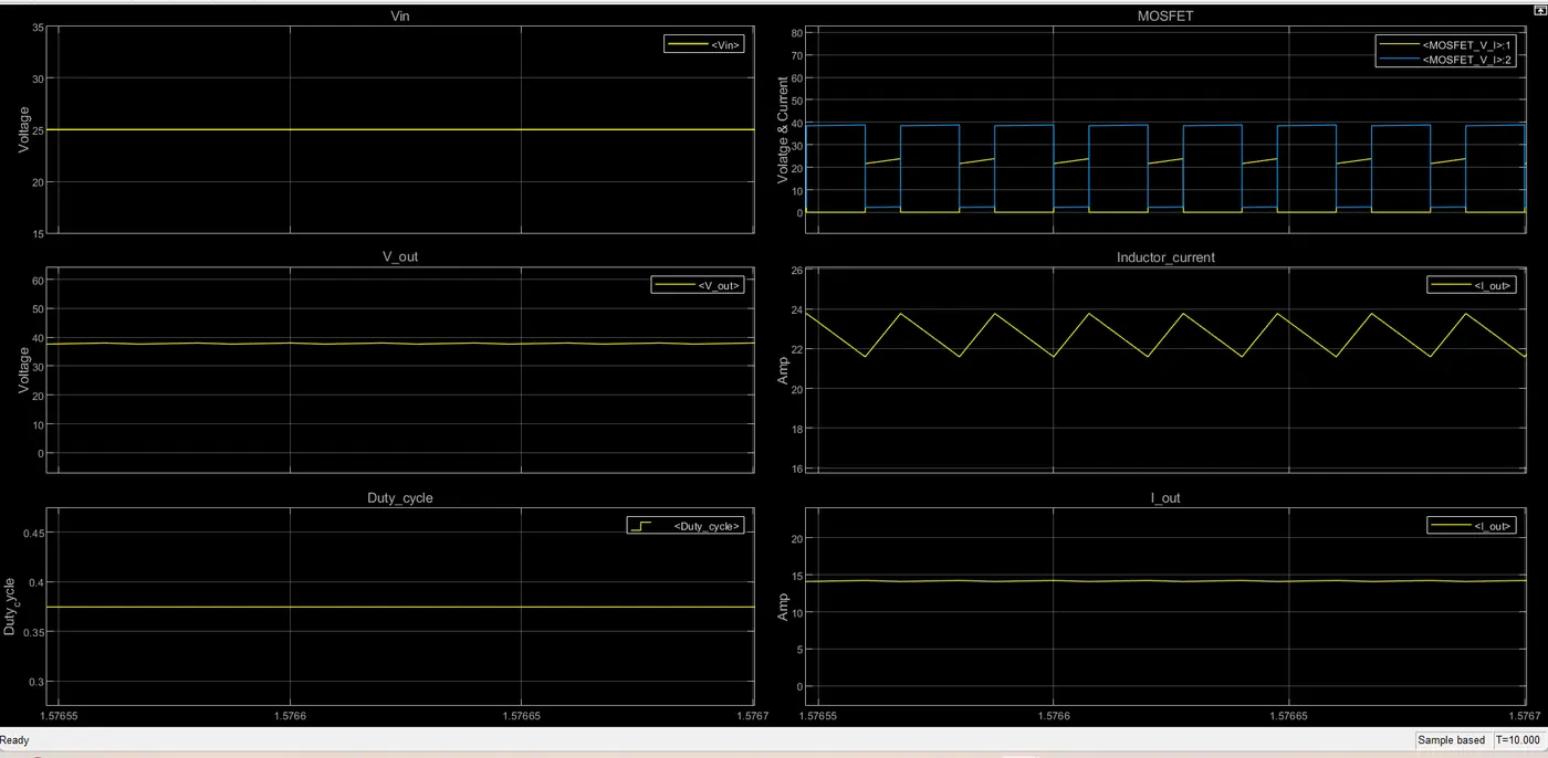
Output:
The end....