Project 1
I AM SELECT THE THREE CONVERTER ARE ,
1)BUCK CONVERTER ( Vin = 40V - 50V ; Vout = 30V) (Vin =400V - 500V ; Vout = 300V)
2)BOOST CONVERTER
3)SEPIC CONVERTER
BUCK CONVERTER
The simulation of buck converter is design using matlab simulink.
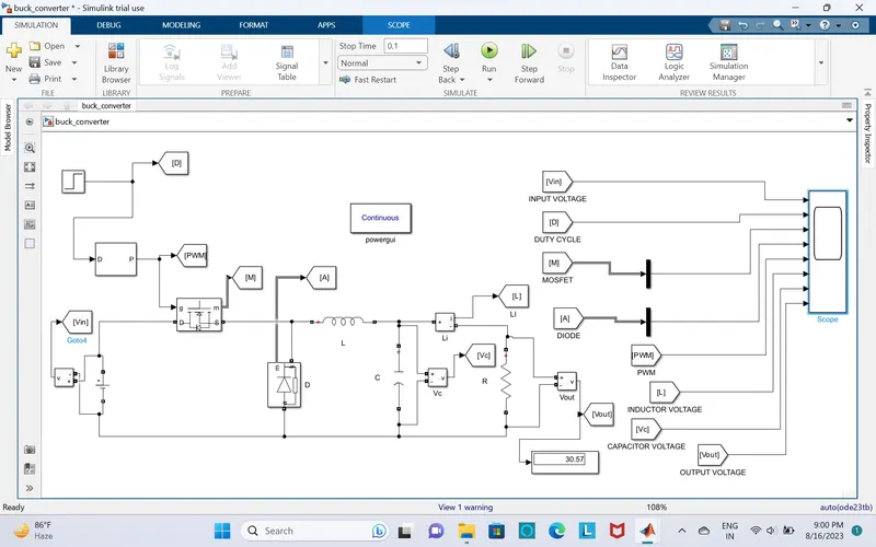
1) Vin = 40V
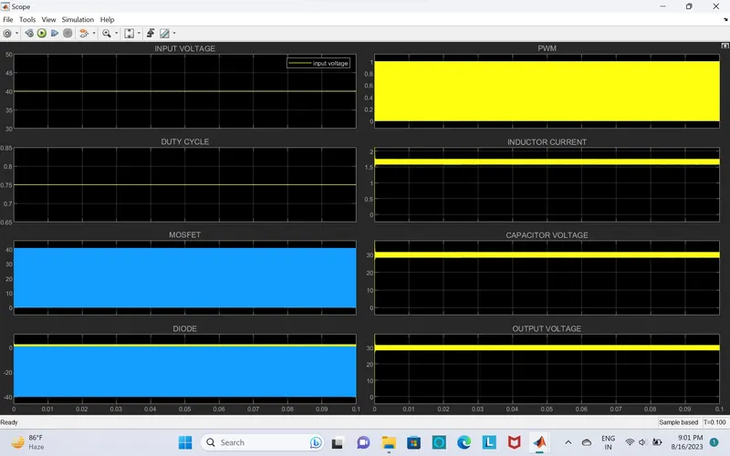
2) Vin = 400V
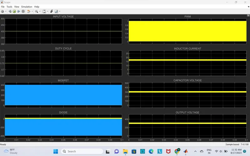
3) Vin = 50V
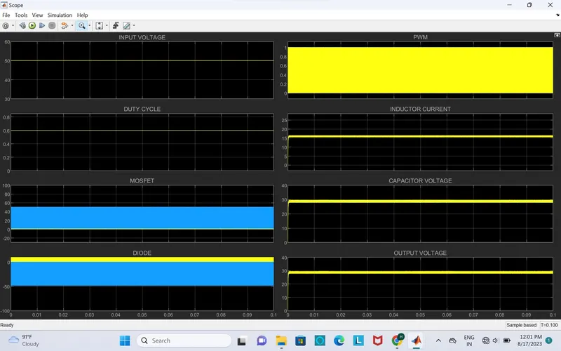
4) Vin = 500V
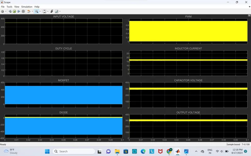
CALCULATION:
Vin = 40V - 50V Vin = 400V - 500V
Vout =30V Vout = 300V
R - RESISTOR IS ABSORB THE POWER
1) DUTY CYCLE
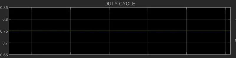
D = Vout/Vin = 30/40 = 0.75
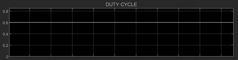
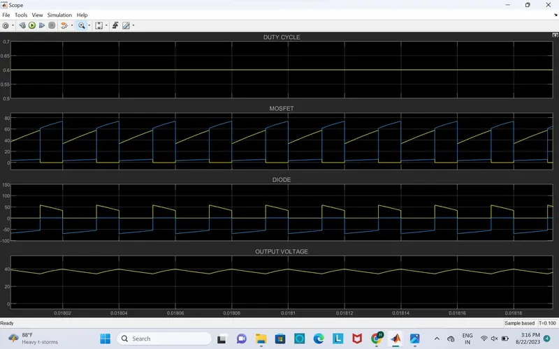
D = Vout/Vin = 30/50 = 0.6
D = Vout/Vin =300/400 = 0.75
D =Vout/Vin = 300/500 = 0.6
2) RESISTOR
Vout = 30V P = 500W :
R = Vout^2/P = (30)^2/500 = 1.8 ohms
R = 1.8 ohms
I = P/Vout = 500/30 = 16.6A
Vout = 300V P = 5000W :
R = Vout^2/P = (300)^2/5000 = 18 ohms
r = 18 ohms
I = P/Vout = 5000/300 = 16.6A
Then design of ripple inductor 10%
delta IL = (10/100)*16.6 = 1.6A
fs = 50khz
3)INDUCTOR:
Vin = 40V AND 400V The duty cycle is 0.75
L = (Vout(1-D)/fs*delta IL) = 30(1-0.75)/50*1.6 = 0.093mH.
Vin = 40V AND 400V The duty cycle is 0.6
L = (Vout(1-D)/fs*delta IL) = 30(1-0.6)/50*1.6 = 0.15mH.
4)CAPACITOR :
LET DESIGN THE OUTPUT CAPACITOR
1) Vin = 40V AND 400V The duty cycle is 0.75
Cout = (1-D)/(8*L*fs^2*(DELTA Vo/Vo)) = (1-0.75)/(8*0.093*50*50*(10/100))
Cout = 0.00134f
Cout = 1.34uf
2) Vin = 50V AND 500V The duty cycle is 0.6
Cout = (1-D)/(8*L*fs^2*(DELTA Vo/Vo)) = (1-0.6)/(8*0.15*50*50*(10/100))
Cout = 0.00133f
Cout = 1.33uf
Show the wave forms by using scope
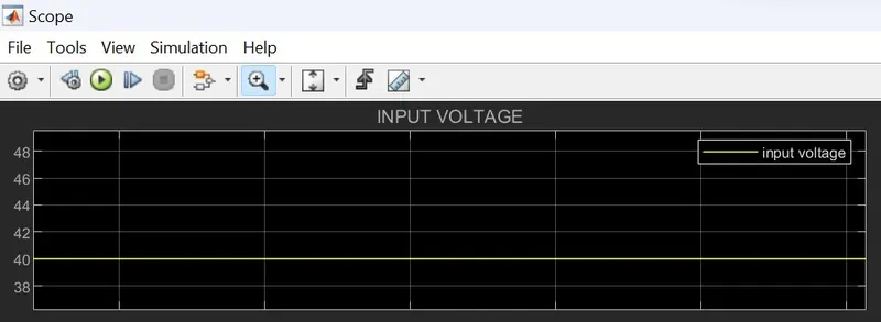
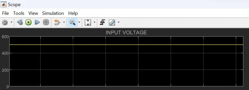
INPUT VOLTAGE IS
Vin = 40V
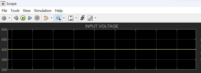
2) Vin = 400V
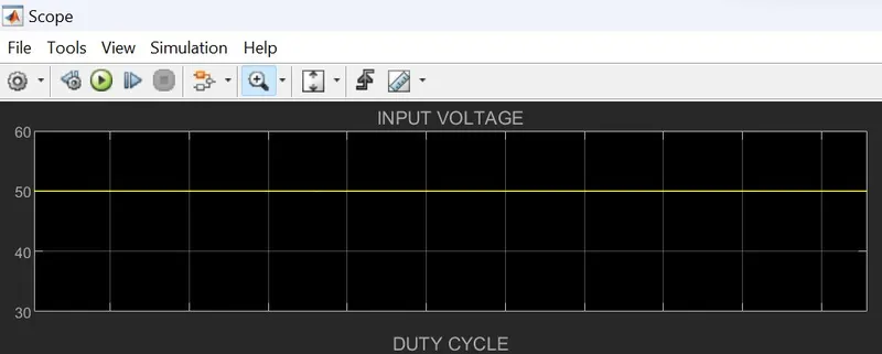
3) Vin = 50V
4) Vin = 500V
DUTY CYCLE AT
1) Vin = 40V AND 400V
2) Vin =50V AND 500V
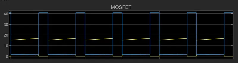
MOSFET
1)Vin = 40V
2) Vin = 400V
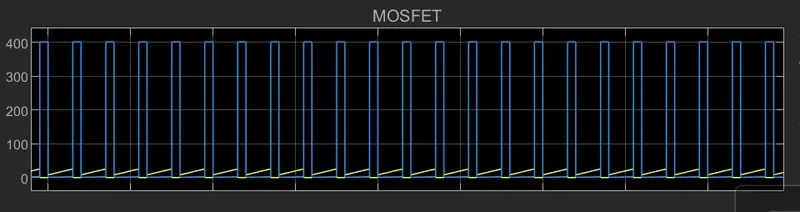
3) Vin = 50V
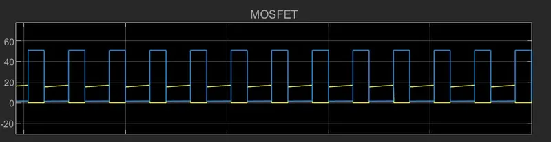
4) Vin = 500V
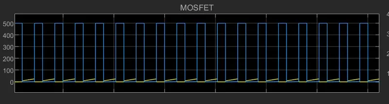
DIODE
1) Vin = 40V
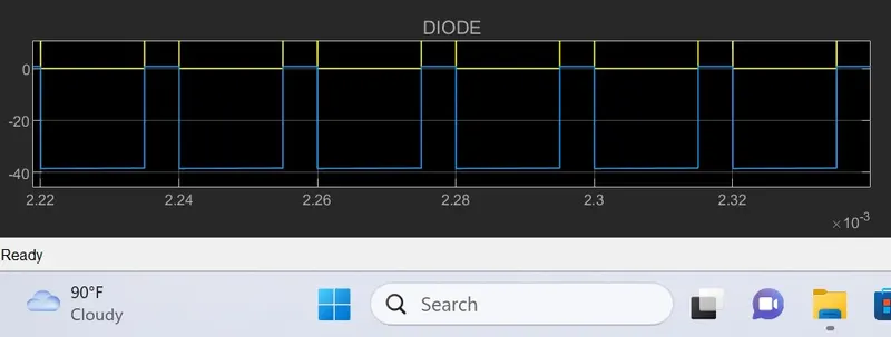
2) Vin = 400V
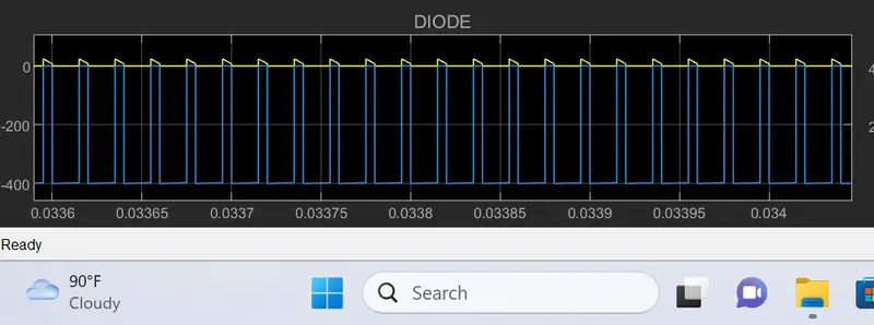
3) Vin = 50V
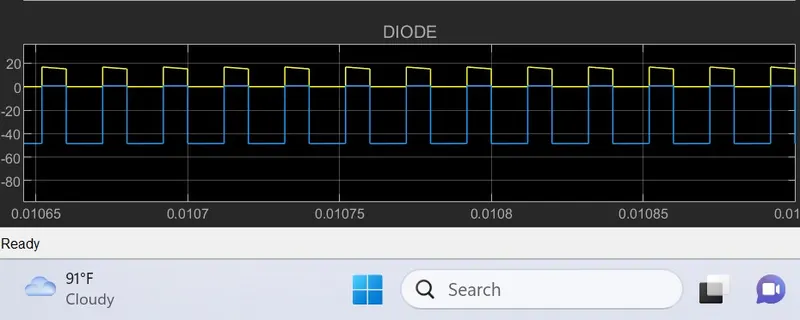
4) Vin = 500V
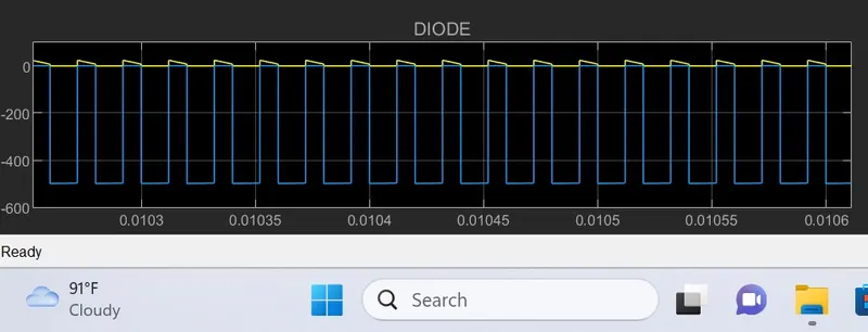
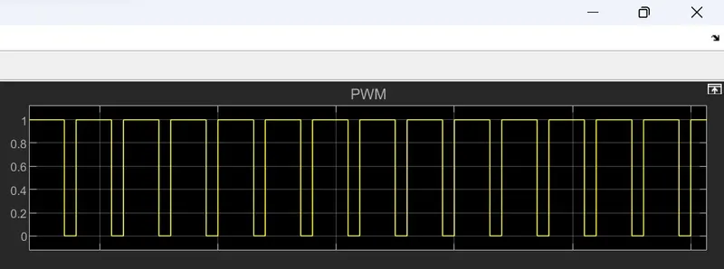
PWM
1) Vin = 40V AND 400V AND 50V AND 500V
INDUCTOR CURRENT
1) Vin = 40V
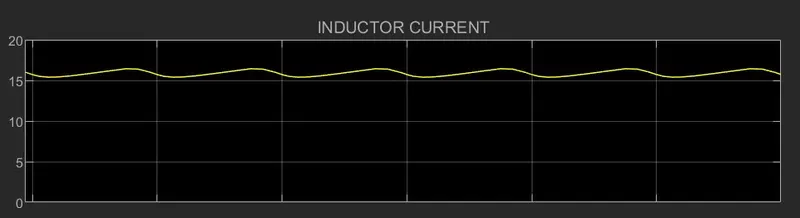
2) Vin = 400V
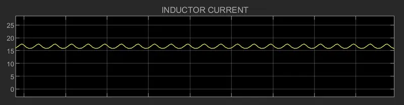
3) Vin = 50V
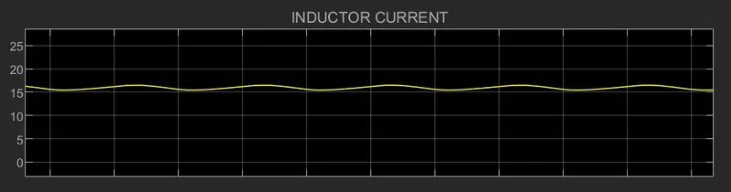
4) Vin = 500V
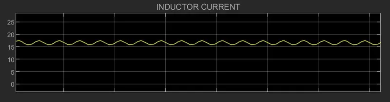
CAPACITOR VOLTAGE
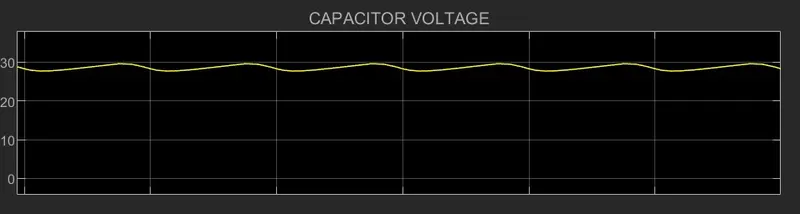
1)Vin = 40V
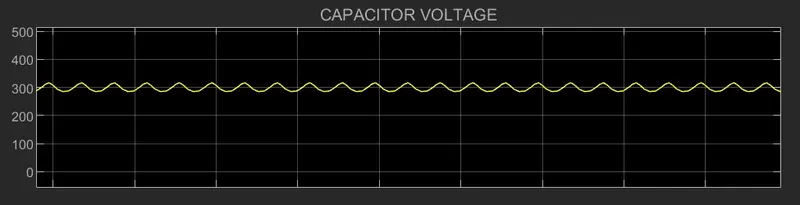
2) Vin = 400V
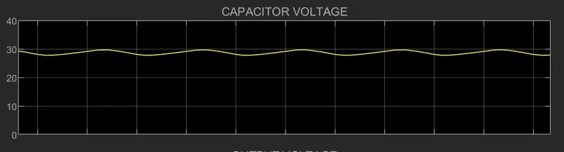
3) Vin = 50V
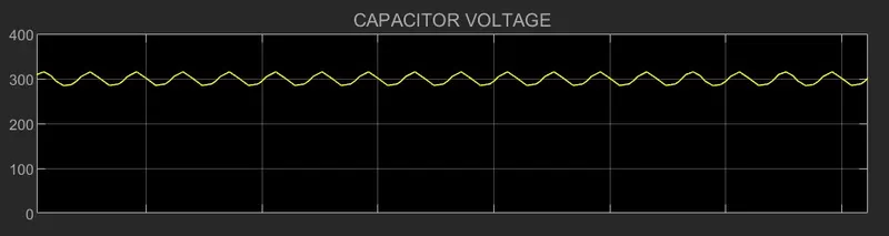
4) Vin = 500V
OUTPUT VOLTAGE
1) Vin = 40V
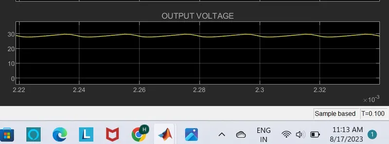
THE OUTPUT VOLTAGE IS 28V
2) Vin = 400V
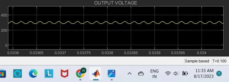
THE OUTPUT VOLTAGE IS 307V
3) Vin = 50V
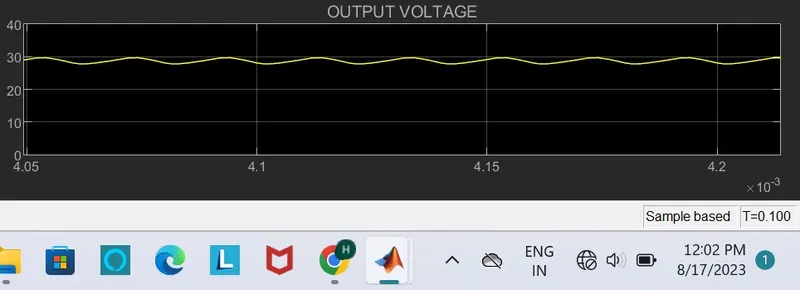
THE OUTPUT VOLTAGE IS 28V
4) Vin = 500V
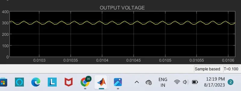
THE OUTPUT VOLTAGE IS 300V
BOOST CONVERTER :
The simulation model of boost converter is ,
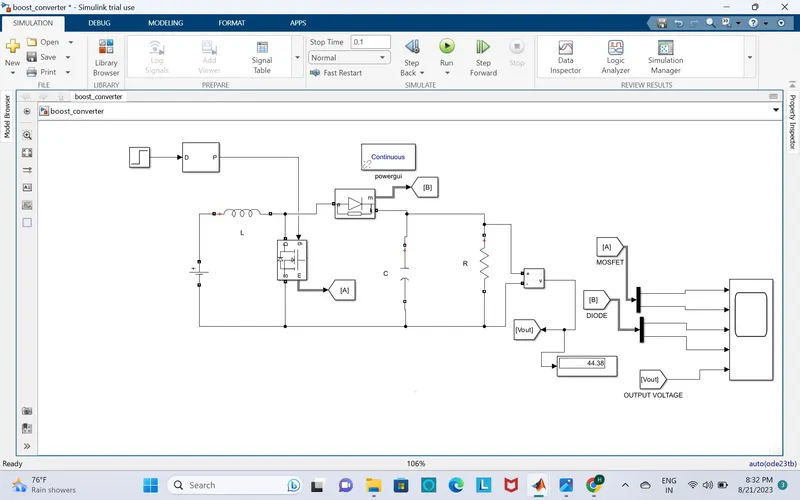
Input Voltage= 20-30V
Output Voltage= 40V
Power = 600W
Switching Frequency = 50 kHz
Therefore, Duty cycle for Boost converter can be calculated as,
Vout/Vin = 1/1-D
Vin 20V
2) 40/20 = 1/1-D
D = 0.5
3) 40/30 = 1/1-D
D = 0.25
Load resistance can be calculated as
R = (Vout)^2/P = 2.67 ohms
INDUCTOR :
To calculate the inductor is,
L = (D(1-D)^2*R)/2*fs
the duty cycle
D = 0.5
L >= (0.5*(1-0.5)^2*2.67)/2*50
L = 0.0033mH
D = 0.25
2)L >= (0.25*(1-0.25)^2*2.67)/2*50
L = 0.0037mH
CAPACITOR :
To calculate capacitor
D = 0.5
1)Cout = D/R*fs*(delta Vo/Vo)
= 0.5/2.67*50*0.1
delta Vo/Vo = 0.1;
Then the ripple is 10% (10/100 = 0.1)
Cout = 0.0374mf
Cout = 37.4uf
D = 0.25
2) Cout = D/R*fs*(delta Vo/Vo)
= 0.25/2.67*50*0.1
C = 0.0936mf
C = 93.6uf
THE OUTPUT VOLTAGE IS 20V :
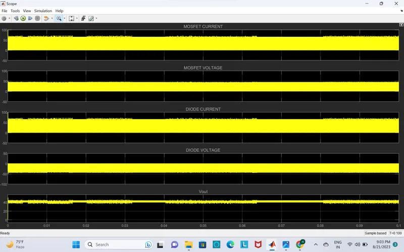
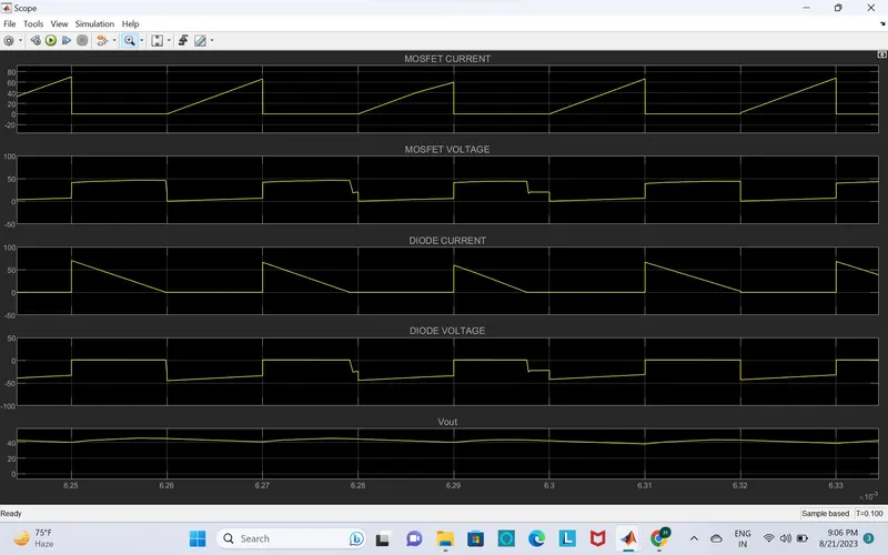
The output voltage is 44V
- 2) THE INPUT VOLTAGE IS 30V :
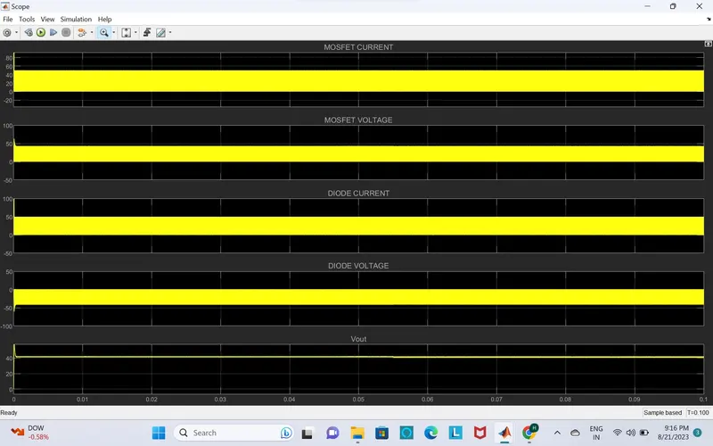
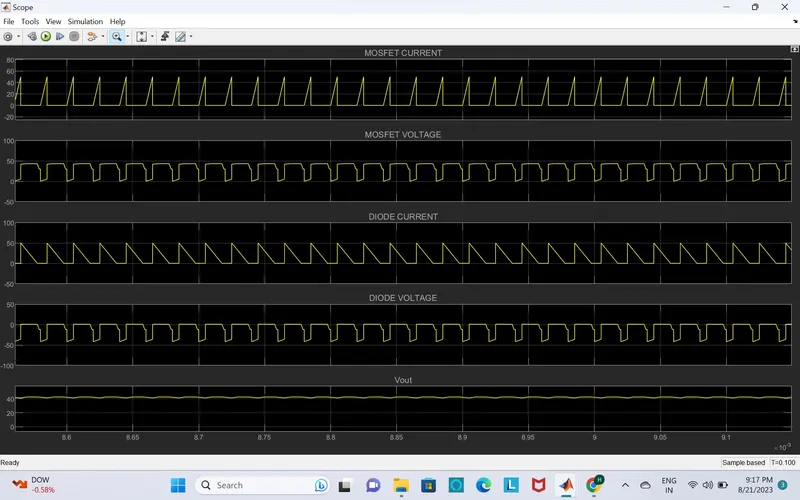
The output is 41.43V
2) BOOST CONVERTER.
I_Diode, Mosfet current and PWM signals are shown below for the input voltage of 200V to 300V.
output voltage is expected as 400V.And the diode and current operates with different ON and OFF situations.
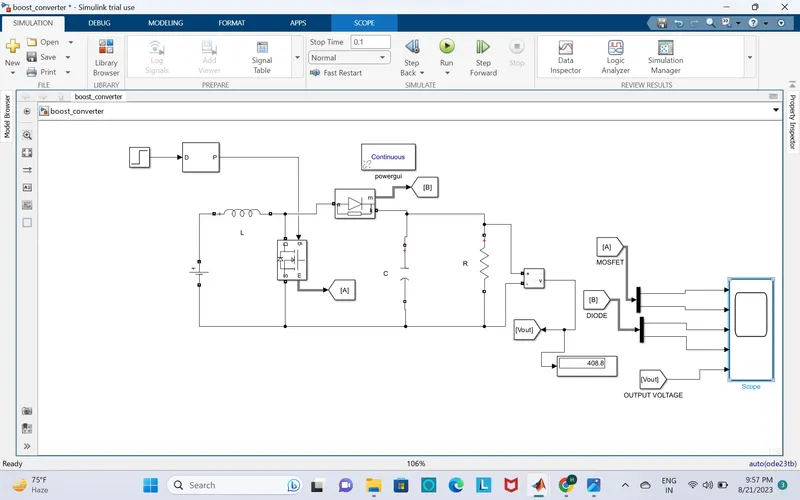
Input Voltage= 200-300V
Output Voltage= 400V
Power = 4KW
Switching Frequency = 50 kHz
Therefore, Duty cycle for Boost converter can be calculated as,
Vout/Vin = 1/1-D
Vin 200V
2) 400/200 = 1/1-D
D = 0.5
3) 400/300 = 1/1-D
D = 0.25
Load resistance can be calculated as
R = (Vout)^2/P = 40 ohms
INDUCTOR :
To calculate the inductor is,
L = (D(1-D)^2*R)/2*fs
the duty cycle
D = 0.5
L >= (0.5*(1-0.5)^2*40)/2*50
L = 0.05mH
D = 0.25
2)L >= (0.25*(1-0.25)^2*40)/2*50
L = 0.056mH
CAPACITOR :
To calculate capacitor
D = 0.5
1)Cout = D/R*fs*(delta Vo/Vo)
= 0.5/40*50*0.1
delta Vo/Vo = 0.1;
Then the ripple is 10% (10/100 = 0.1)
Cout = 0.0025mf
Cout = 2.5uf
D = 0.25
2) Cout = D/R*fs*(delta Vo/Vo)
= 0.25/40*50*0.1
C = 0.0012mf
C = 1.2uf
THE INPUT VOLTAGE IS 200V
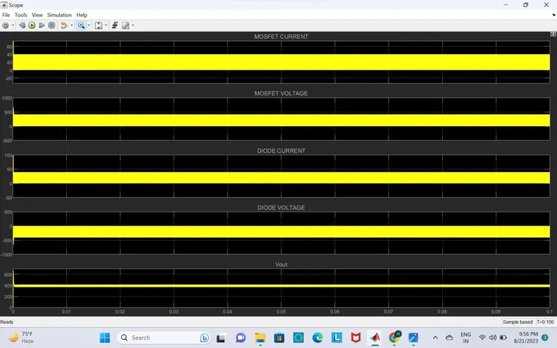
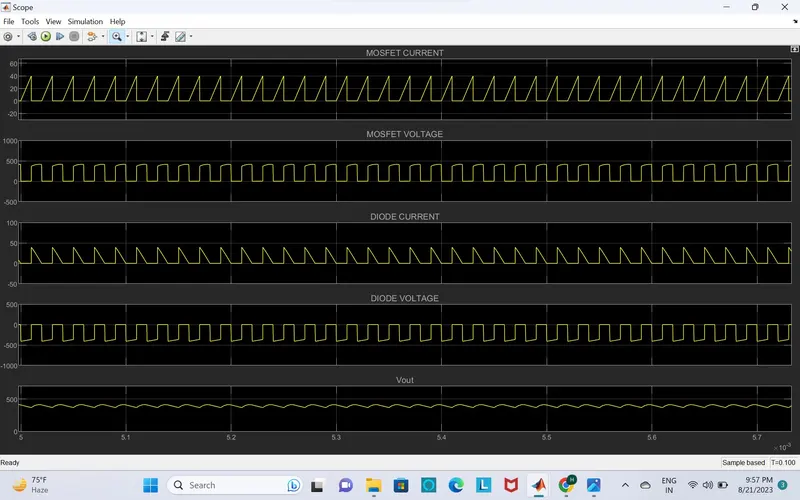
THE OUTPUT VOLTAGE IS 408V
2) THE INPUT VOLTAGE IS 300V
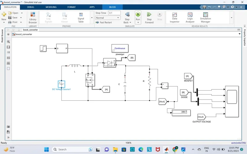
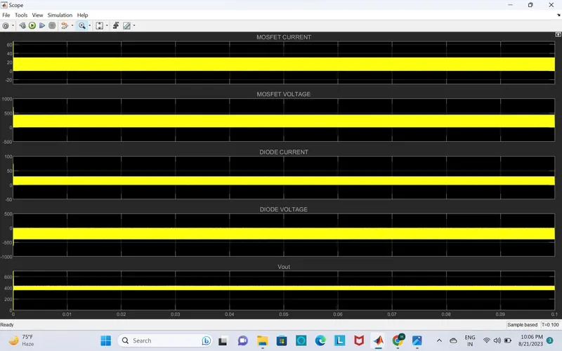
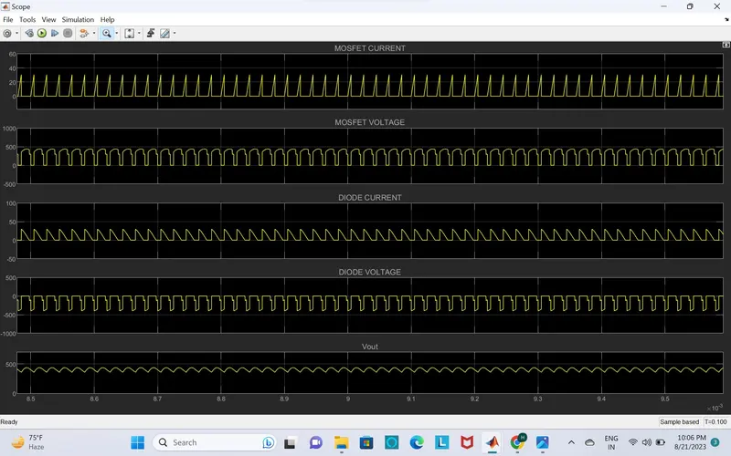
THE OUTPUT VOLTAGE IS 399.7V
SEPIC CONVERTER :
Given data ;
The input voltage range is Vin = 30V to 60V
The output voltage is Vout = 45V
The power (P) = 1KW = 1000W
Output voltage ripple must be less then 10%
CALCULATION :
To calculate the DUTY CYCLE
Vout/Vin = D/1-D
I) Vin = 30V 2) Vin = 60V
45/30 = D/1-D 45/60 = D/1-D
45-45D = 30D D = 45/105
D = 45/75 D = 0.42
D = 0.6
THE DUTY CYCLE RANGE IS 0.6 TO 0.42
current
* Iout = P/Vout = 1000/45 = 22.22 amp
* Iout = 22.22 amp
To calculate resistance
R = Vout/Iout = 45/22.22
R = 2.02 ohms
now will be design sepic inductors
1) IL1 = P/Vin = 1000/30 = 33.33A (Vin = 30V)
IL1 = P/Vin = 1000/60 = 16.66A (VIN = 60V)
2) IL2 = P/Vout = 1000/45 = 22.22A
Vin = 30V
L1 = (Vin *D/fs*delta IL1) = (30*0.6/50*33.33) = 0.010mH
L2 = (Vin *D/fs*delta IL2) = (30*0.6/50*22.22) = 0.016mH
Vin = 60V
L1 = (Vin *D/fs*delta IL1) = (60*0.42/50*16.66) = 0.030mH
L2 = (Vin *D/fs*delta IL2) = (60*0.42/50*22.22) = 0.022mH
CAPACITOR
deltaVc1 = 0.1*30 = 3V
deltaVc1 = 0.1*60 = 6V
C1 = Vout*D/R*fs*deltaVc1
C1 = 45*0.6/2.02*50*3 = 27/303 = 89uf
C1 = 45*0.42/2.02*50*6 = 18.9/606 = 31uf
Cout = D/R*fs*(DELTA .Vo/Vo)
i) C2 = D = 0.6 = 0.6/2.02*50K*0.1 = 0.0594mf = 59.4uf
ii)C2 = D = 0.42 = 0.42/2.02*50K*0.1= 0.0415mf = 41.5uf
SIMULATION OF DESIGN A SEPIC CONVERTER :
1) The result of output wave form of the input voltage,the duty ratio,the output voltage"including the ripple" and the inductor current "including the ripple".
FOR,
Vin = 30V
DUTY CYCLE = 0.6
L1 = 0.010mH
L2 = 0.016mH
C1 = 89uf
C2 = 59.4uf
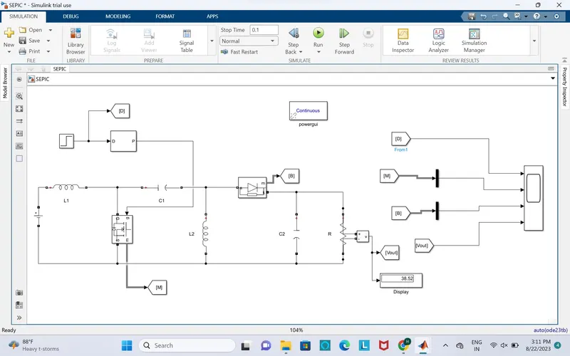
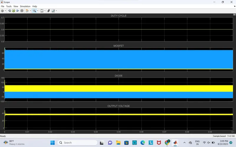
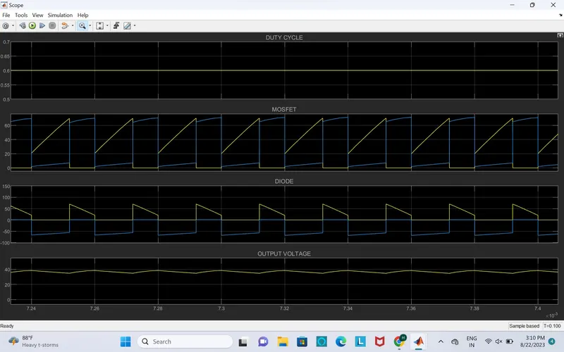
The output is 38V
2)
Vin = 60V
DUTY CYCLE = 0.42
L1 = 0.030mH
L2 = 0.022mH
C1 = 31uf
C2 = 41.5uf
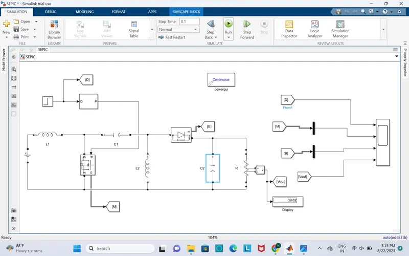
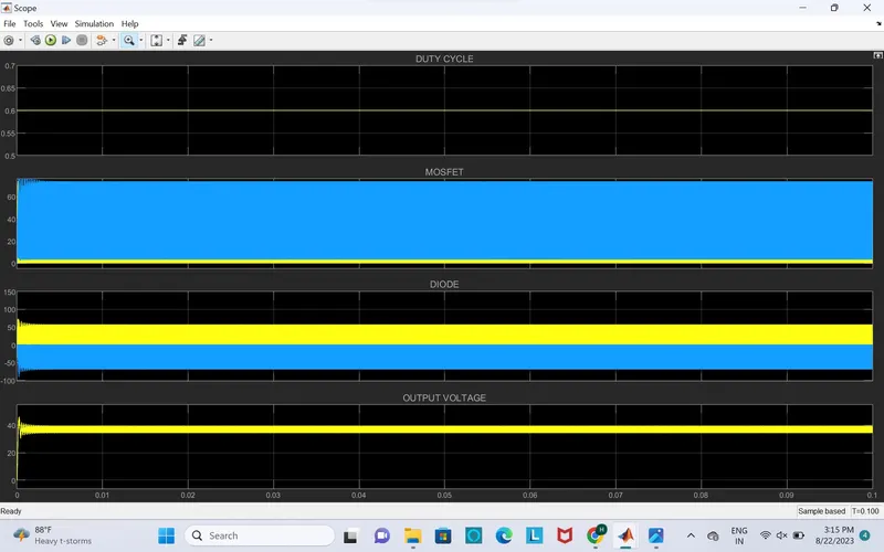
The outut is 39.62V
..'''''''''''''.........................END .................................................