Project 1
Choose any three topologies and develop the models in Simulink.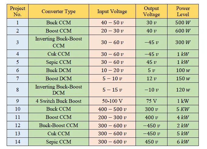
The project design report should include the following:
1- A Design report to show the reasoning behind your choices of inductance and capacitance levels in your design.
2- The full schematics of your converter including gate drivers, PWM chips, RC circuits, current sensors, voltage sensors, etc…
3- A complete simulation file including all the necessary waveforms and justifying all the chosen components sizing (you have to show the system ability to track the output voltage at different dynamic conditions).
4- The full specs for all the needed components in your circuit.
Note: Feel free to deviate from the provided specs as long as you are using the assigned converter. However, you can not copy the specs of another assigned converter
Project no - 1: Buck converter.
Given data:
Input voltage Vin = 50V;
output voltage Vo = 30V;
output power Po = 500W;
To find a 'duty cycle';
D = (Vout/Vin);
D = (30/50);
D = 0.6V;
To find a output curret 'Io';
Io = (Po/Vo);
Io = (500/30);
Io = 16.67A;
To find a 'Ro' load resistance value,
Ro = (Vo/Io);
Ro = (30/16.67);
Ro = 1.79 Ohms.
To find a inductance 'L',
L = (Vo/Fs*(deltaIL))*(1-D);
Delta Il = (Ripple value/100)*Io;
Assume ripple value = 30%;
Delta Il = (30/100)*16.67;
Delta Il = 5.001A:
L = (30/(50000*5.001))*(1-0.6);
L = 0.000048 H;
To find a capacitance value 'C',
C = (1 - D)/(8*L*(F^2)*(Delta Vo/Vo));
Delta Vo = (Ripple voltage/100)*Vo;
Assume ripple voltage at 5%,
Delta Vo = (5/100)*30;
Delta Vo = 1.5 V;
C = (1-0.6)/(8*0.000048*(50000*50000)*(1.5/30));
C = 0.0000833 F;
Operating circuit diagram,
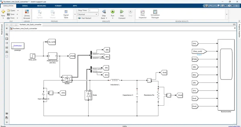
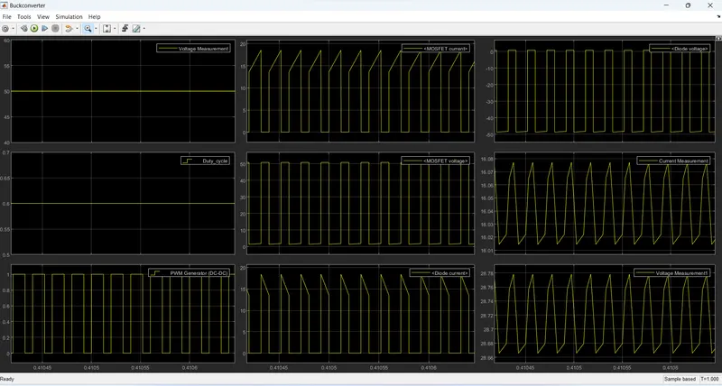
Output graph zoomout ,
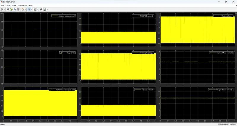
Output graph at zoomin,
Project no 2: Boost converter.
Given data:
Input voltage Vin = 20 - 30V;
Output voltage Vout = 40V;
Output power Po = 600 W;
Frequency F = 50K Hz;
To find a duty cycle 'D',
Define 'D' duty cycle,
D=> (Vo/Vin)=(1/(1-D));
(1-D)*Vo = Vin;
(Vo-(D*Vo)) = Vin;
(D*Vo) = Vin-Vo;
D = (Vin-Vo)/Vo;
D = (30-40)/40;
D = 0.25;
To find a inductance 'L';
L = (Vin/F*delta Il)*D;
Delta Il = (Ripple % current/100)*Il;
Il = (Vin/((1-D)^2)*R;
We have a rasistance value Ro.so,
Ro = (Vo^2)/Po;
Ro = (40^2)/600;
Ro = 2.67 Ohms;
Il = (30/(0.25^2)*2.67;
Il = 20A;
Delta Il = (30/100)*20;
Delta Il = 6A;
L = ((30/(50000*6))*0.25;
L = 0.000025 H;
To find a capacitance 'C',
C = (D/Ro*F*(Delta Vo/Vo));
Delta Vo = (Ripple voltage value/100)*Vo;
Delta Vo = (5/100)*40;
Delta Vo = 2V;
C = (0.25/2.67*50000*(2/40));
C = 0.000374 F;
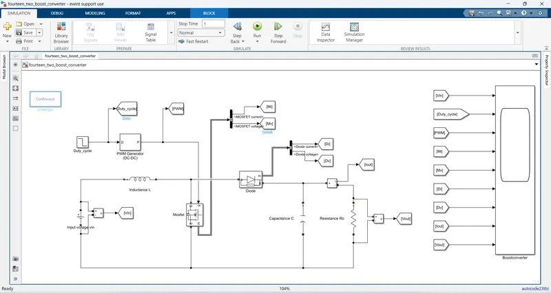
Operating circuit diagram,
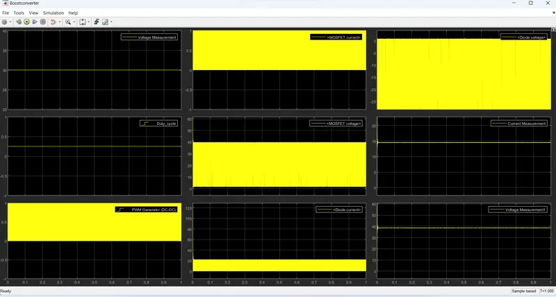
Output graph zoomout,
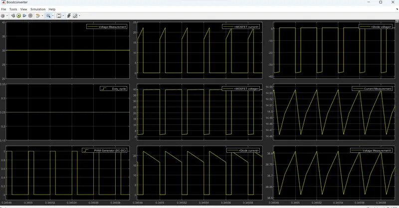
Output graph zoomin,
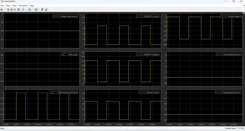
Project no - 4: Cuk converter.
Given data :
Input voltage Vin = (30 - 60)V;
Output voltage Vo = -45V;
Output power Po = 1 KW;
Frequency F = 50K Hz;
Solution:
To find a duty cycle value 'D',
Define Duty cycle ,
D=> (Vo/Vin) = (-D/(1-D));
Vo*(1-D) = Vin(-D);
Vo - (Vo*D) = -(Vin*D);
We know about 'Vo' and 'Vin' value. So,but in value in above equivation,
(-45)-(-45D) = (-60D);
(-45)+45D = (-60D);
-45 = (-60D -45D);
-45 = (-105D);
D = (-45/-105);
D = 0.42.
To find a load resistance Ro,
Ro = (vo^2)/Po;
Ro = (-45^2)/1000;
Ro = 2.025 Ohms;
To find a inductance 'L1' and 'L2',
L = (Vin/F*Delta.Il)*D;
Delta Il = (% ripple value/100)*Il;
Il = (Power/Voltage);
Il1 = (Po/Vin);
Il1 = (1000/60);
Il1 = 16.67 A;
Il2 = (Po/Vo);
Il2 = (1000/(-45));
Il2 = -22.22 A;
Delta Il1 = (30/100)*16.67;
Delta Il1 = 5.001 A;
Delta Il2 = (30/100)*(-22.22);
Delta Il2 = -6.67 A;
L1 = (60/50000*5.001)*0.42;
L1 = 0.001007 H;
L2 = (60/50000*(-6.67))*0.42;
L2 = -0.000755 H;
To find a capacitance 'C1' and 'C2';
C1 = (Vo*D)/(Ro*F*DeltaVc1);
DeltaVc1 = (%rpple value/100)*Vc1;
Vc1 = (Vin-Vo);
Vc1 = (60-(-45));
Vc1 = 105 V;
Delta Vc1 = (5/100)*105;
DeltaVc1 = 5.25 V;
C1 = ((-45)*0.42)/(2.025*50000*5.25);
C1 = -0.000355 F;
C2 = (1-D)/(8*L2*(F^2)*(DeltaVc2/Vo));
Vc2 = Vo;
Vc2 = -45 V;
DeltaVc2 = (5/100)*(-45);
DeltaVc2 = -2.25 V;
C2 = (1-0.42)/(8*(-0.000755)*(50000*50000)*(-2.25/-45));
C2 = -0.00000768 F;
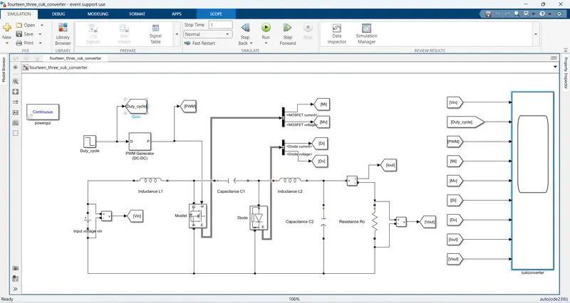
Operating circuit of Cuk converter;
Output graph in Zoomout,
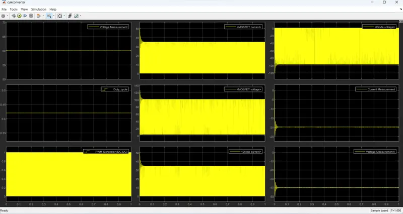
Output graph in zoomin,