Project 1
1 ans:-
AIM of the project:-
The Main Of this project is Design the battery pack configuration ,Draw the BMS topology for this battery pack using given data and also build 3s2p battery pack configuration by using the MATLAB/SIMULINK tool.
Given data
Power rating = 150Kw
Voltage rating = 120V
Cell nominal volage =3.6 V
Cell Nominal Capacity = 3500 mAh
So, Battery Ampere hour = 150Kw/120V = 1250 Ah
Now , we need to find the No of cells in series and parallel to meet requirement. The requirement condition is 120V, 1250 Ah
Cells in Series:-
Number of cell in series = Required Voltage/Cell Nominal Voltage
Number of cell in series = 120/3.6
= 33.33
Now we need to round off, We have two cases
Case 1- No of cells in series = 34
Case 2- No of cells in Parallel = 33
Case 1
Nominal battery voltage = cell nominal voltage * No of cells in series
= 3.6 * 34
= 122.4 V
Case 2
Nominal battery voltage = cell nominal voltage * No of cells in series
= 3.6 * 33
= 118.4 V
It is always better to prefer higher voltage. There fore no of cells in series is 34
Cells In Parallel :-
No of cell in parallel = Rated Current / Cell Nominal Capacity
No of cell in parallel = 1250/3.5
= 357.14
Case 1- Roundoff to 357
Battery capacity = rated capacity of a cell * no of cells in parallel
= 3.5* 357
= 1249.5 Ah
Case 2- Roundoff to 358
Battery capacity = rated capacity of a cell * no of cells in parallel
= 3.5* 358
= 1253 Ah
So we are considering no of cells in parallel is 358
So our battery pack configuration is 34S348P
b) ans:-
Draw the BMS topology for this battery pack.:-
Battery management system (BMS) is technology dedicated to the oversight of a battery pack, which is an assembly of battery cells, electrically organized in a row x column matrix configuration to enable delivery of targeted range of voltage and current for a duration of time against expected load scenarios.
The battery management system is critical to the battery’s safe operation, overall performance, and longevity of battery pack.
The primary function of the BMS is to protect the battery cells from damage caused by being overcharged or over- discharged. Additionally, the BMS calculates the remaining charge, monitors the battery’s temperature, monitors the battery’s health and safety by checking for loose connections and internal shorts.
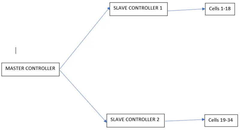
if the 34 cells in series in the battery pack, we have to use Master-Slave topology as the BMS topology in which Master/slave is a model of communication for hardware devices where one device has a unidirectional control over one or more devices. This is often used in the electronic hardware space where one device acts as the controller, whereas the other devices are the ones being controlled.
Here, a master controller is connected to 2 slave controllers with their respective AFEs , where the first slave controller is having 18 cells and the second controller is having 16 cells.
2 ans :- 3S2P battery pack configuration with generic battery block using Matlab/Simulink :-
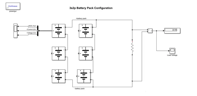
The battery pack configuration is 3S2P. Which means no of cells in series is 3 and No of cells in parallel is 2
The total No of cells = 3*2 = 6
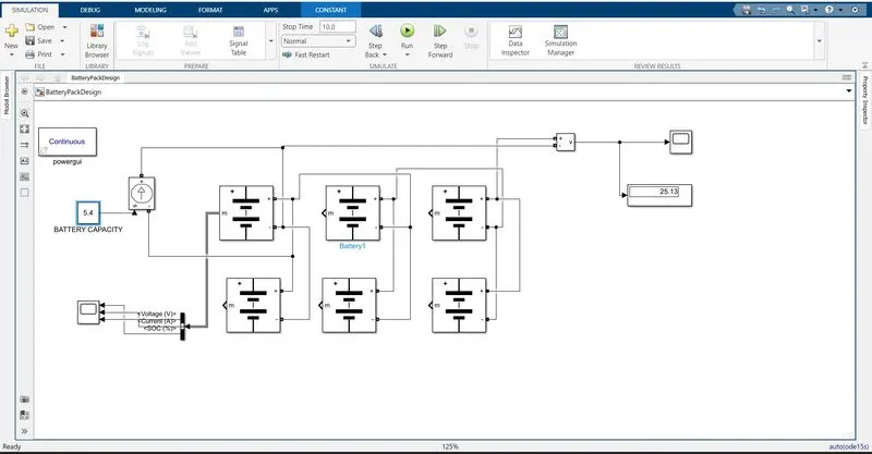
The figure below shows the 3S2P battery pack configuration in simulink.
Explanation
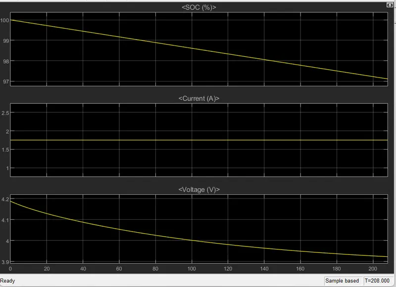
if the resistor is connected to battery pack as a Load. The voltage measurement block along with scope and display is connected across the battery pack to measure battery pack voltage. With the help of bus selector a scope is connected to Cell, which gives SOC, Voltage and current of the cell. The simulation is done for 100 Sec and output is observed.
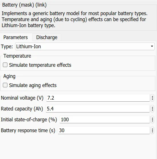
Specifications:
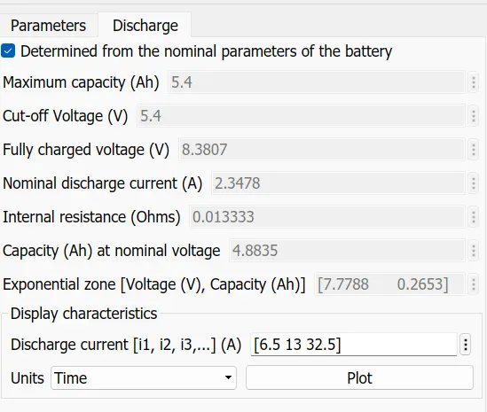
explanation
Cell Nominal Voltage = 7.2 V
Rated capacity of cell = 5.4Ah
Nominal Voltage of battery Pack = Max voltage of cell * No of cell
= 7.2 V * 3 = 21.6 V
Rated Capacity of battery pack = Rated capacity of cell * no of cells in parallel
= 5.4 * 2 = 10.8 Ah
Overall Voltage of battery pack = Max voltage of cell * No of cell
= 8.3 * 3 = 24.9 V
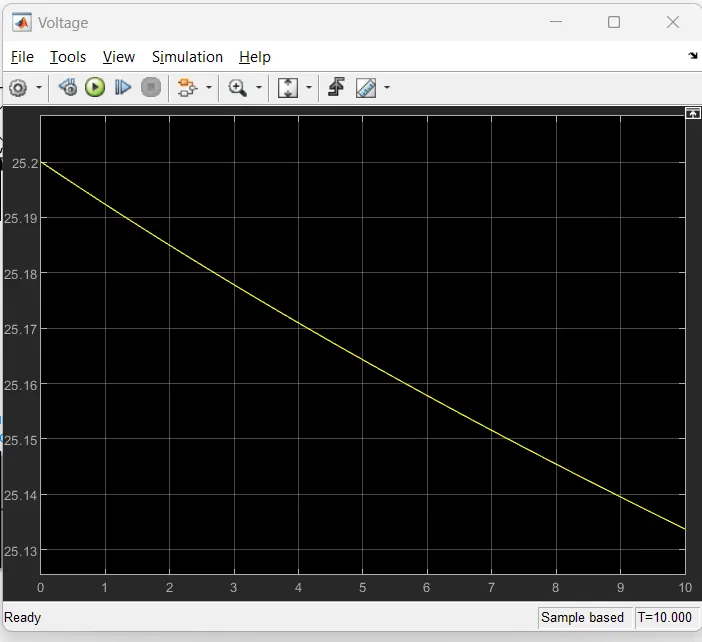
Output Scope results :-
Voltage scope :-
Overall voltage of the battery pack = maximum voltage of the battery * no. of cells in series
= 8.3V * 3 = 25 V
- Single battery output for SOC,Current and Voltage:-