Project 1
Project No 1:
Buck Converter with closed-loop control :
a) For continuous conduction mode, two duty cycle values are found from V_input minimum( 40 V) and V_input maximum(50V):
duty_cycle1= 0.75, L_minimum= 0.21mH
duty_cycle1= 0.6, L_minimum= 0.432mH
To ensure continuous load current at any range of input voltage, we considered L_minimum= 0.432mH.
b) To limit the output voltage ripple to 10% (let),
we calculated C_minimum= 16.16 micro F.
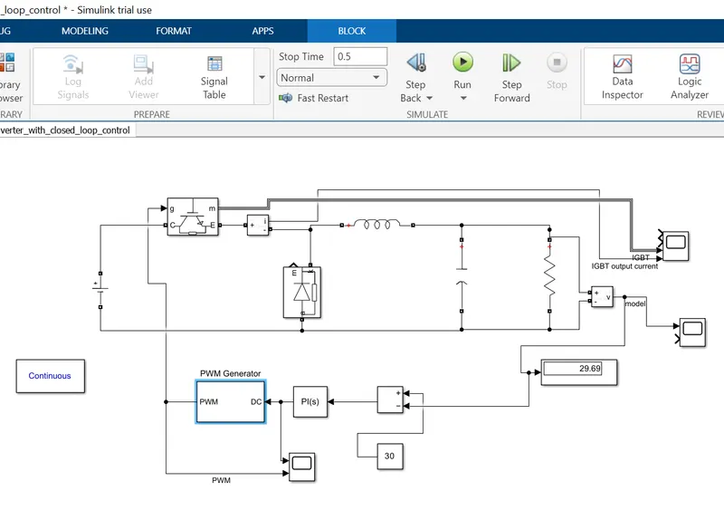
c) For closed-loop control, the output voltage is continuously measured by connecting the voltage sensor across the load, and output voltage feedback is fed to the comparator to compare with a reference voltage (here its value is 30V). Accordingly error signal is generated which is passed through the PI controller.
In the PI controller, Proportional gain=1.5( To increase response time.)
Integral constant= 1
The output of the PI controller is passed through the PWM generator to generate gate pulse according to the duty cycle.
Project No 2:
Boost Converter with closed-loop control :
a) For continuous conduction mode, two duty cycle values are found from V_input minimum( 20 V) and V_input maximum(30V):
duty_cycle1= 0.75, L_minimum= 0.312mH
duty_cycle1= 0.5, L_minimum= 0.834mH
To ensure continuous load current at any range of input voltage, we considered L_minimum= 0.312mH as using L_minimum= 0.834mH, noticeable difference did not observe. So to make the model economical, we used a lower inductance value for input voltage =20 V.
b) To limit the output voltage ripple to 10% (let),
we calculated C_minimum= 14.04 micro F.
c) For closed-loop control, the output voltage is continuously measured by connecting the voltage sensor across the load, and output voltage feedback is fed to the comparator to compare with a reference voltage (here its value is 40V). Accordingly, an error signal is passed through the PI controller(Closed loop control).
In the PI controller, Proportional gain=0.01(To produce PI output less than one.)
Integral constant= 1
The output of the PI controller is passed through the PWM generator to generate gate pulse according to the duty cycle.