Project 1
AIM : The double-acting actuator model using Simscape Multibody and Simscape components. The mechanical system of the cylinder needs to be built using Simscape Multibody library components / blocks, and the hydraulic system needs to be modelled using Simscape library physical components.
Modeling a Double-Acting Actuator
This example shows how to model a double-acting actuator with Simscape™ Multibody™ and Simscape. Simscape Multibody models the mechanical system of the cylinder, and Simscape models the hydraulic system. You can use block to connect the two systems.
Cylinder Model
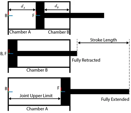
The schematics show the cylinder in three configurations: half-retracted, fully retracted, and fully extended.
- Library:
-
Simscape / Foundation Library / Mechanical / Multibody Interfaces

Description
The Translational Multibody Interface block implements an intuitive way to connect Simscape™ blocks that have mechanical translational ports with Simscape Multibody™ joints that have prismatic primitives. Simscape blocks that can be connected to a Translational Multibody Interface block include:
-
Blocks from the Foundation > Mechanical > Translational Elements library, such as Translational Friction or Translational Damper.
-
Blocks with mechanical translational ports from other Foundation libraries, such as Translational Mechanical Converter (G) or Translational Mechanical Converter (IL).
-
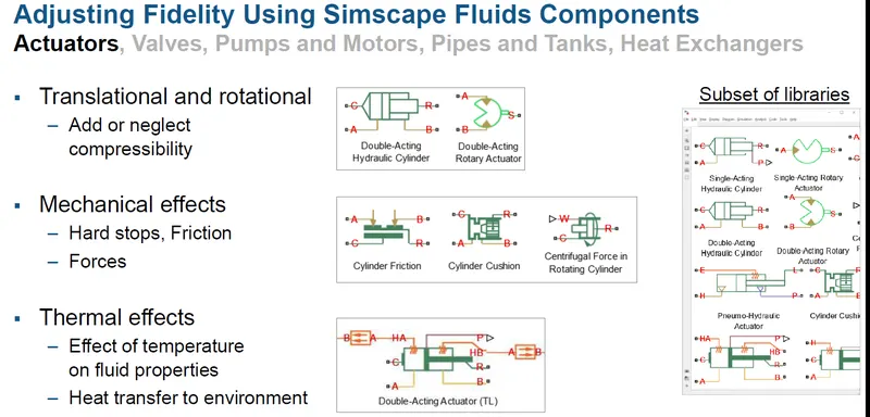
Blocks with mechanical translational ports from add-on products, such as hydraulic actuators from the Simscape Fluids™ libraries.
The Translational Multibody Interface block matches the force and relative velocity across the interface. You can connect it to any Simscape Multibody joint that has a prismatic primitive:
-
Enable the velocity sensing port v and the force actuation port f on the joint. If the joint has multiple degrees of freedom, make sure that the selected velocity sensing and force actuation correspond to the same degree of freedom.
-
Connect physical signal ports v and f of the Translational Multibody Interface block to ports v and f of the Simscape Multibody joint.
-
Connect ports C and R of the Translational Multibody Interface block to a Simscape mechanical translational network.
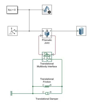
For detailed step-by-step instructions, see
Blocks like Translational Friction and Translational Damper do not require position information, and for these blocks the interface based on force and relative velocity is sufficient. Other blocks, like hydraulic actuators, require information on relative position between their ports. To connect these blocks to a Simscape Multibody joint:
-
Use the Translational Multibody Interface block. Enable the velocity sensing port v and the force actuation port f on the joint, and connect the ports as described above.
-
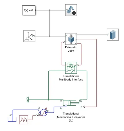
Additionally, enable the position sensing port p on the joint. If the joint has multiple degrees of freedom, make sure that the position and velocity sensing and force actuation all correspond to the same degree of freedom.
-
On the actuator block, enable the position input port p, by setting the Interface displacement parameter to
Provide input signal from Multibody joint. Connect the position input port p on the actuator block to the position sensing port p of the Simscape Multibody joint.
Assumptions and Limitations
For models with Translational Multibody Interface or Rotational Multibody Interface blocks, it is recommended that you use Simscape Multibody blocks to model masses and inertias. The reason is that Simscape networks need to have a ground (reference) node, with all the masses and inertias in the network accelerating with respect to this node. In a Simscape Multibody joint, both the base and follower frames may be accelerating. Therefore, a mass or inertia in the Simscape network connected to a joint may not have the correct inertial reference.
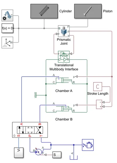
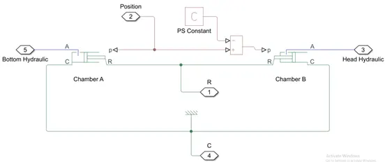
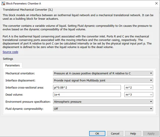
In chamber A, a pressure at port A moves the piston from 0 to stroke length. The displacement of the piston equals to the position output of the Prismatic Joint block. To model chamber A:
-
Connect the ports C and R of the Translational Multibody Interface block to the ports C and R of the upper Translational Mechanical Converter (IL) block, respectively.
-
In the Translational Mechanical Converter (IL) block, set Interface displacement to
Provide input signal from Multibody jointto enable port p. -
Connect ports p of the Prismatic Joint block and Translational Mechanical Converter (IL) block.
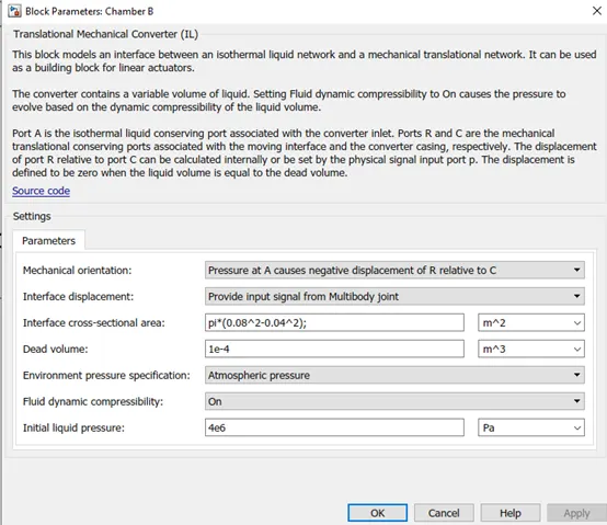
In chamber B, the pressure at port A moves the piston from 0 to negative stroke length. Therefore, you need to change the default orientation and add an offset to the input position signal of the lower Translational Mechanical Converter (IL) block. The offset equals -dB.
-
In the lower Translational Mechanical Converter (IL) block, set Mechanical orientation to
Pressure at A causes negative displacement of R relative to C. -
Set Interface displacement to
Provide input signal from Multibody jointto enable the port p. -
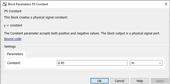
Add a PS Constant block and specify the constant as the stroke length of the cylinder.
-
Add a PS Subtract block, then connect it to the PS Constant and Prismatic Joint blocks as shown in the diagram. Note that the output of the PS Subtract block equals -dB.
To limit the travel of the piston:
-
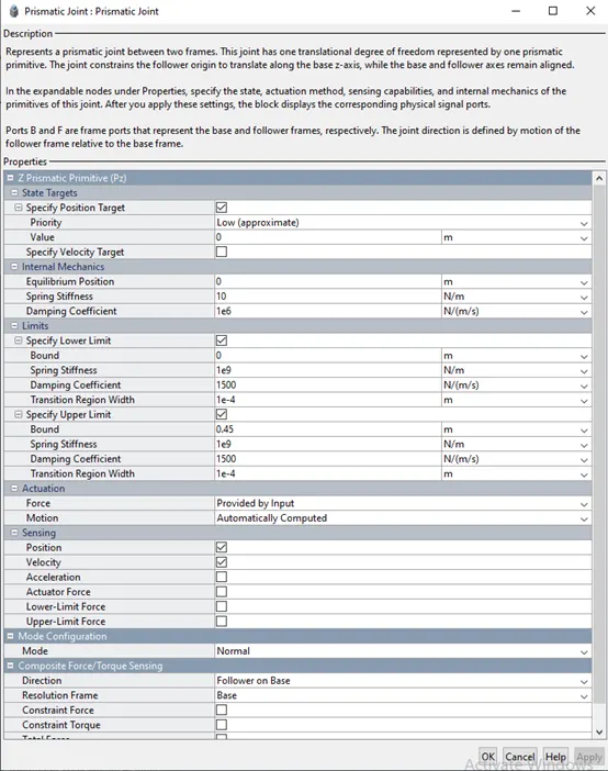
In the Prismatic Joint block, under the Limits section, select the Specify Lower Limit and Specify Upper Limit parameters.
-
Under the Specify Lower Limit section, the Bound parameter indicates the minimum distance between the frames B and F of the joint block. In this example, specify the Bound parameter as 0 m.
-
Under Specify Upper Limit, the Bound parameter indicates the maximum distance between frames B and F of the Prismatic Joint block. In this example, specify the Bound parameter as the stroke length of the cylinder.
Double-acting cylinder systems can be used in many applications. For example, a dump trailer can use a double-acting cylinder to actuate a scissor hoist mechanism that raises and lowers the dump bed. See (Simscape Multibody) for more details. Under the mask of the Double-Acting Hydraulic Cylinder block in the scissor hoist are the mechanical and hydraulic subsystems, which are connected by a Translational Multibody Interface block. The Prismatic Joint block in the mechanical subsystem provides the position information to the two actuators in the hydraulic subsystem, Head Chamber and Bottom Chamber, that have the opposite settings of the Mechanical orientation parameter. The Constant block C provides a position signal offset to the Head Chamber actuator, because when the Bottom Chamber is at dead volume (where position p = 0), the Head Chamber is at maximum stroke.
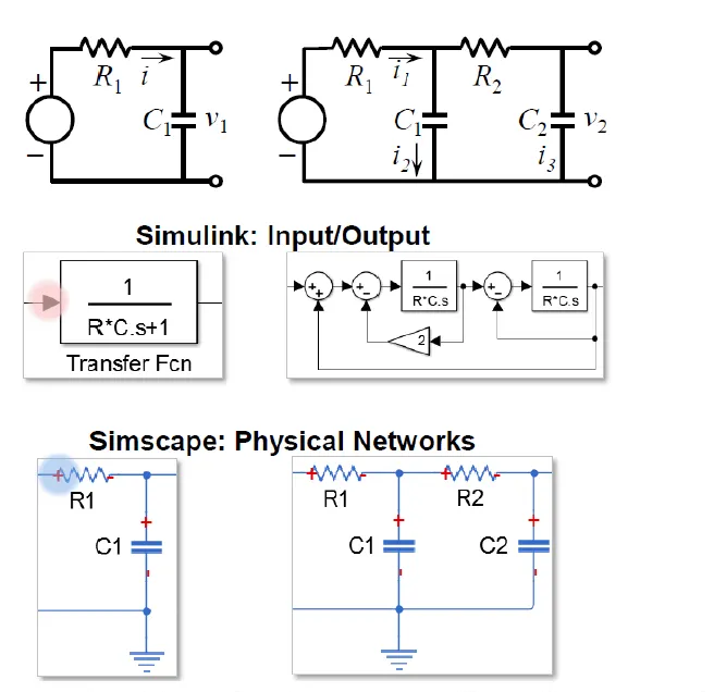
Physical Modeling with Simulink :
Simulink is best known for signal
based modeling
– Causal, or input/output
Simscape enables bidirectional
flow of energy between
components
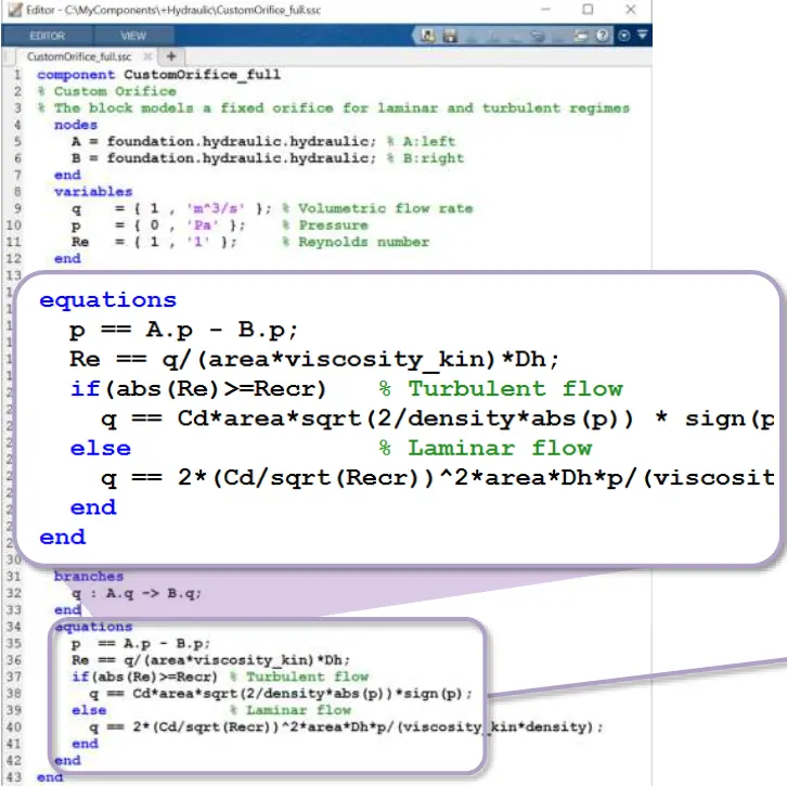
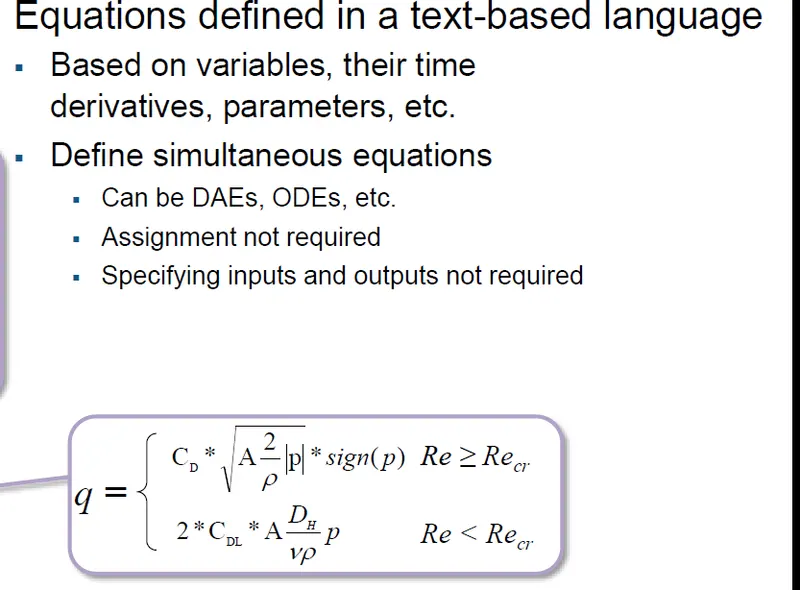
System level equations:
– Formulated automatically
– Solved simultaneously
– Cover multiple domains


Mechanical system:

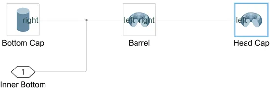
1.Cylinder Assembly:
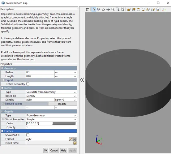
Bottom Cap:
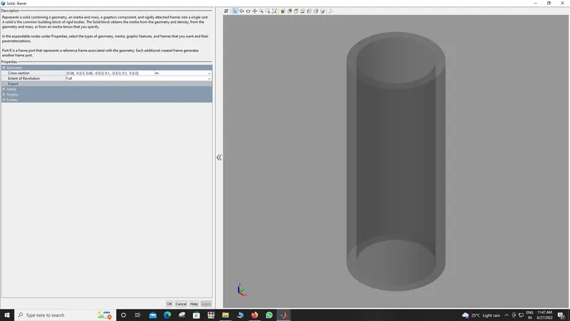
Barrel Cap:
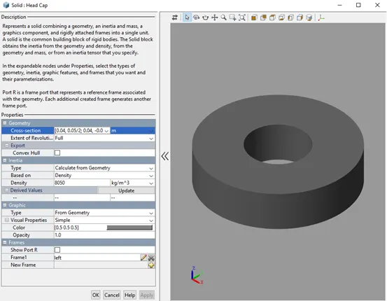
Head Cap:
- Prismatic Joint:
A prismatic joint is often called a slider — for example, a “crank-slider linkage.” This is a type of kinematic pair and an idealized way to describe how motions are constrained within machines.
There are several physical embodiments of a prismatic joint, such as slideways. Rectangular cross-sections may be used in combination with plain or rolling bearings to enable linear motion while preventing rotation about the axis of movement.
Hydraulic and pneumatic cylinders are typically modeled as prismatic joints although they may also permit rotation about their axis. Kinematic pairs are classified as higher pairs and lower pairs. Higher pairs involve point or line contact, such as a ball or roller that’s rolling over a surface. Lower pairs can be visualized as surface contact.
- Piston Assembly:
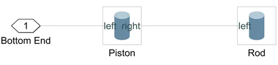
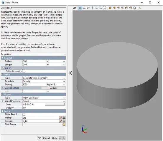
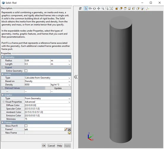
The inlet or outlet flow inside the barrel pushes the Piston or Plunger of hydraulic cylinders. When the Piston moves to either side of the cylinder, the Rod contracts or expands.
These are the parts of the basic hydraulic cylinders. More types of cylinders are more complex in their construction. However, these components are essential to almost all hydraulic cylinders, and it is good to know what they are and how they work.
Piston:
Rod:
Hydraulic system:
Chamber A:
Chamber B:
C:
Hydraulics:
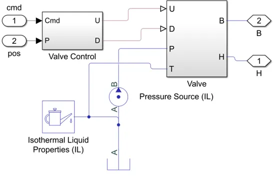
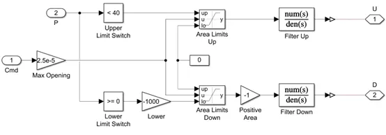
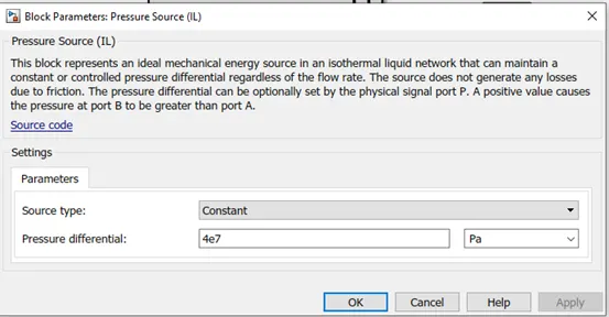
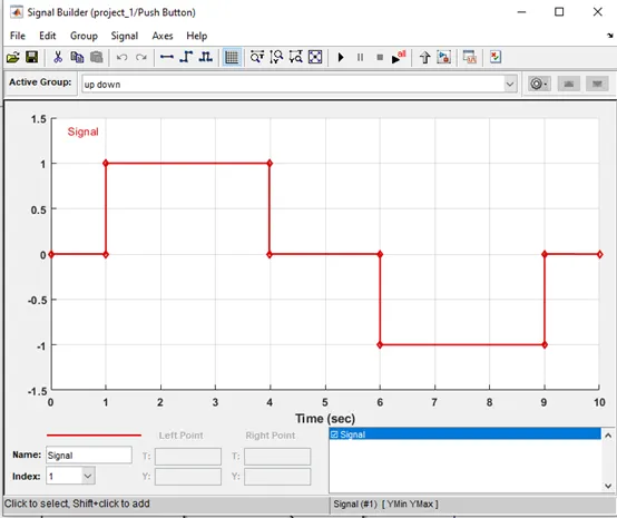
Valve Control:
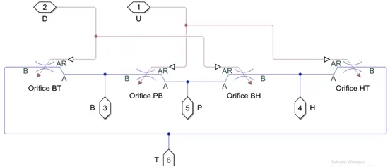
Valve:
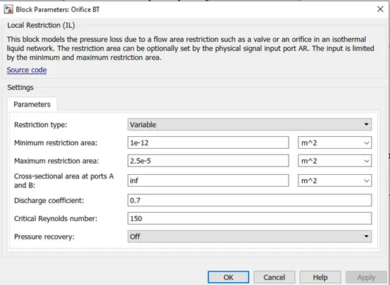
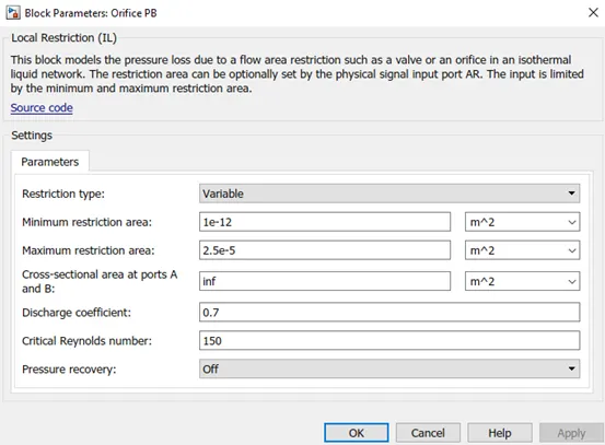
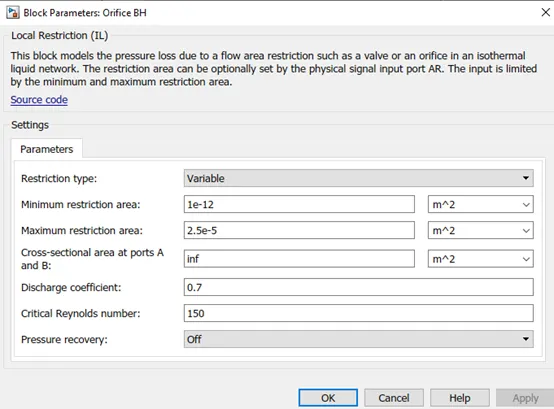
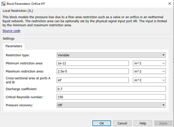
Iso thermal liquid properties:
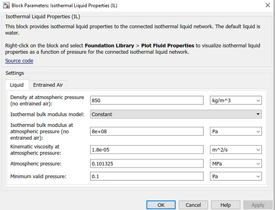
isothermal liquid domain, the working fluid is a mixture of liquid and a small amount of entrained air. Entrained air is the relative amount of non-dissolved gas trapped in the fluid. You can control the liquid and air properties separately: You can specify zero amount of entrained air.
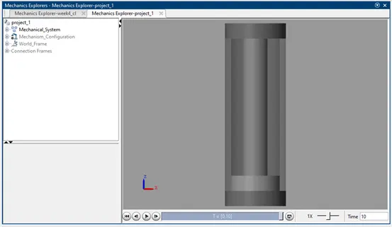
Result: The animation of the acutuator can be observed while running the Simulink file attached below.