AUTOMOTIVE WIRING HARNESS ROUTING DEVELOPMENT
AIM : To root the wiring harness of the given V16 engine and flatten the wiring harness into the 2D drawing sheet from the all necessary industrial design rule and best industrial best practices.
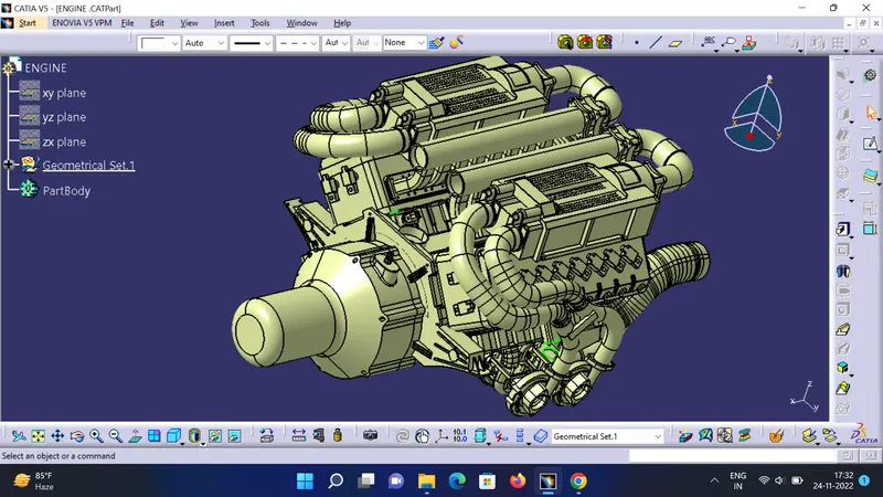
This is a 16 valve V16 engine where 8 cylinders are placed in each side of the engine. In this engine there are 23 sensors are required to harness the wire to route to an inter connector.The sensors consists of 16 injectors,2 engine fly wheel sensors, 4 cam shaft sensors and 1 engine temperature sensor.Generally 4 pole connectors are used for engine injectors.The plastic guiding channel used in this harness can withstand at least 150 degree celsius.The bend ratio given to the all bundle segment is 1.4 and a minimum slack percentage of 10%.
STEP 1
CREATING CONTEXT ASSEMBLY
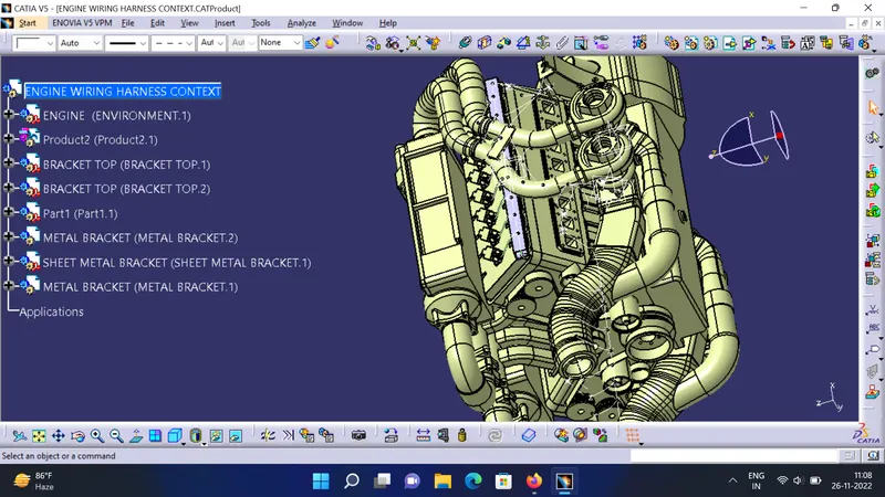
A context assembly has been created it will act as the main assembly product and it will contain the engine environment and the sheet metal design if we needed.
STEP 2
DEFINE THE CONNECTORS ELECTRICALLY
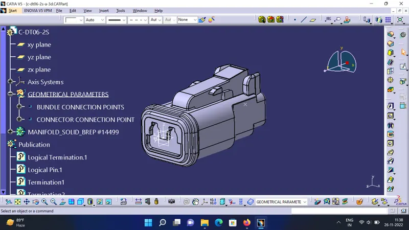
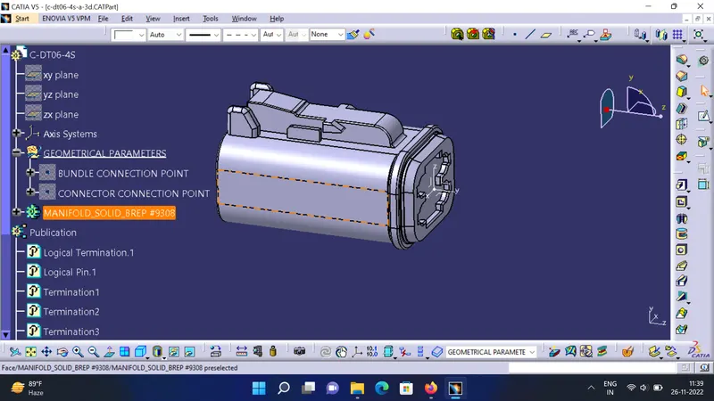
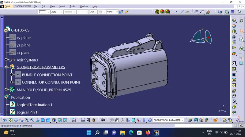
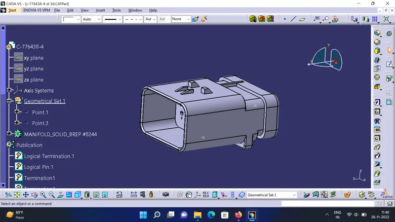
According to the requirments we are using 4 types of connectors which includes 2,4,6 and 12 poles connectors.The cad data is downloaded from te.com.To define a connector electrically we need some geometrical parameters like connector connection point,cavity connection point etc.. in electrical part design workbench.
STEP 3
ADDING ALL THE CONNECTORS INTO THE CONNECTOR PORTS
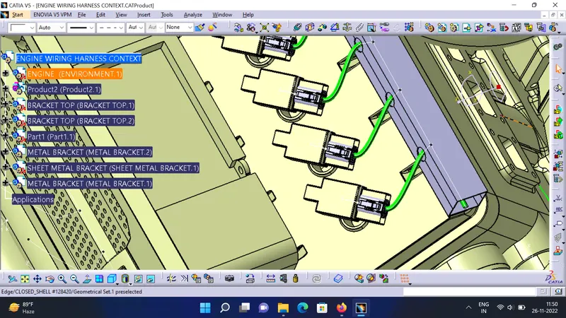
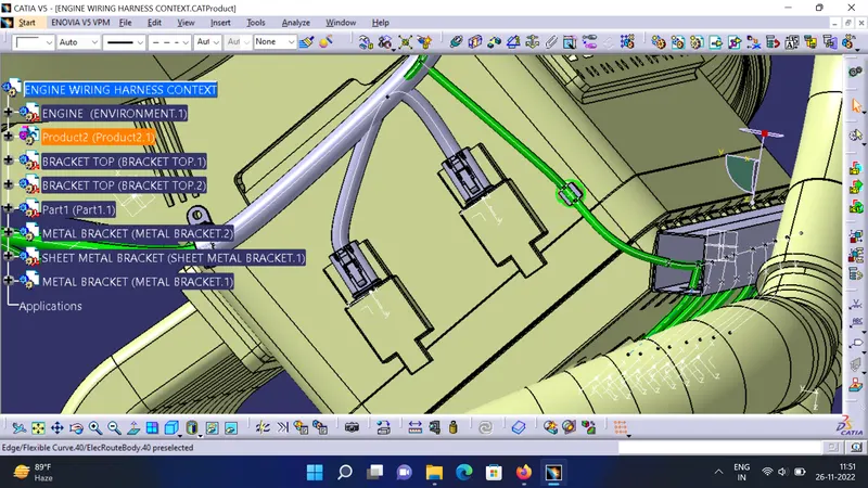
We are placing all the connectors to the exact position where it should be. we are adding all the connectors to the bundle assembly. we have to use manipulation tools along with compass, snap and smart mode.
STEP 4
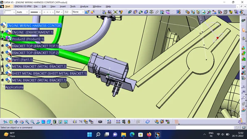
ADDING THE SHEET METAL BRACKET
we want to mount the sheet metal bracket inorder to mount the inter connection connectors.but we have to make sure that the bracket is placed inside the context assembly and outside the engine and geometrical assembly.the bracket should have a bracket system so that dont move freely.there is a rib working has a lock system and we can use that.
STEP 5
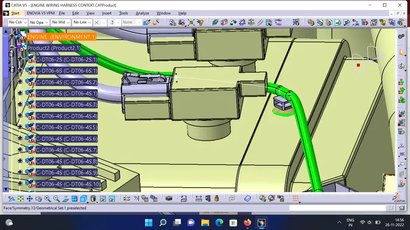
MOUNTING THE INTERCONNECTION CONNECTORS,P-CLAMPS AND FURR TREE CLIPS
A 12 pole connector "C-776438-4" and mounting cavity "C-1924487-2" is together used as interconnection connector. The required cad data is downloaded from te.com. First, we have to define 12 pole connector and mounting cavity electrically as below.
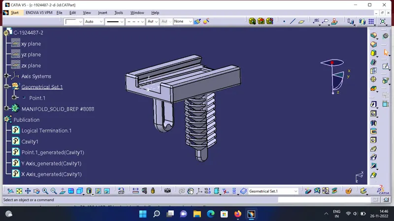
we have to mount that electrically connected interconnection connector and cavity on sheet metal bracket as shown in above figure.
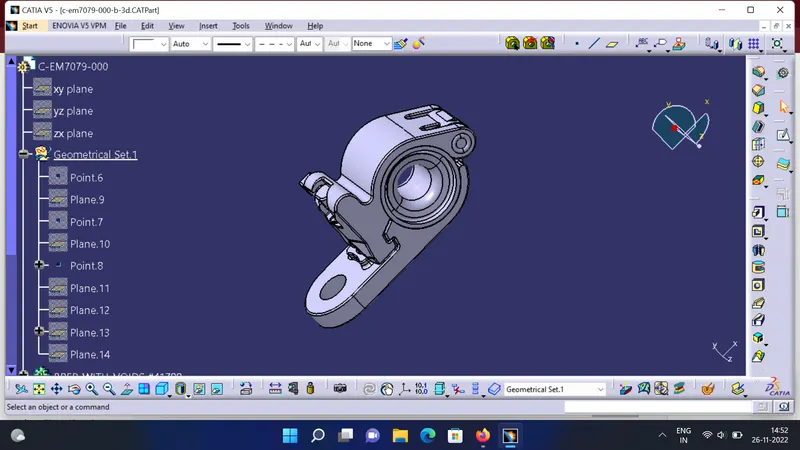
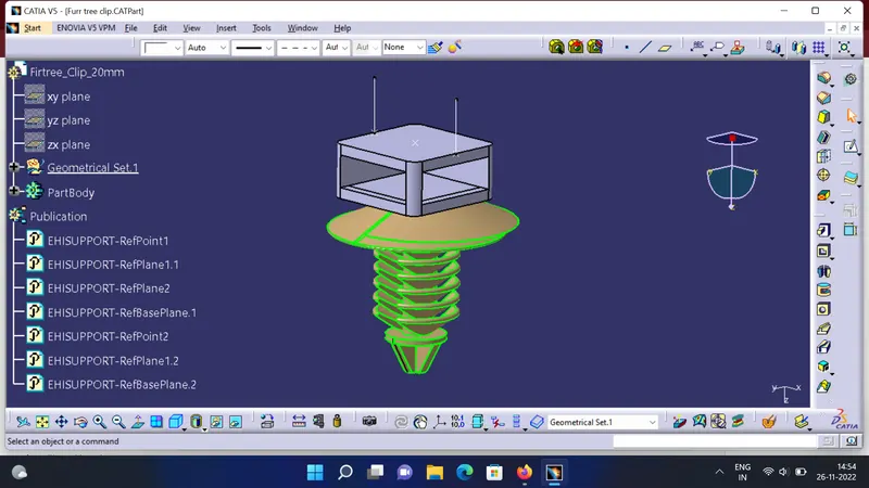
we have mounted furr tree clip also for the smooth path to wiring harness routing towards guiding channel on both right and left side.
STEP 6
MOUNTING THE GUIDING CHANNEL
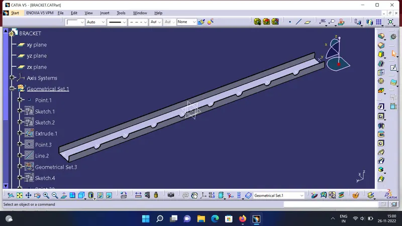
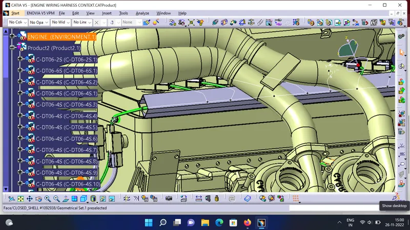
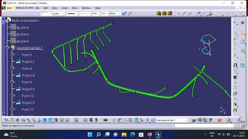
We have to add now plastic guiding channel because Bugatti V16 engine has 8 injectors on right side and 8 injectors on left side which are very close to each other. Hence plastic guiding channel is best option for proper and easy routing of the wiring harness. It will reduce the complex wiring harness routing. We will require two different guiding channel for both right and left side of the engine. Now, before placing guiding channel, we have to define geometrical parameters of guiding channel as below.
STEP 7
BUNDLE ROUTING FROM INTER CONNECTION CONNECTOR TO P CLAMPS
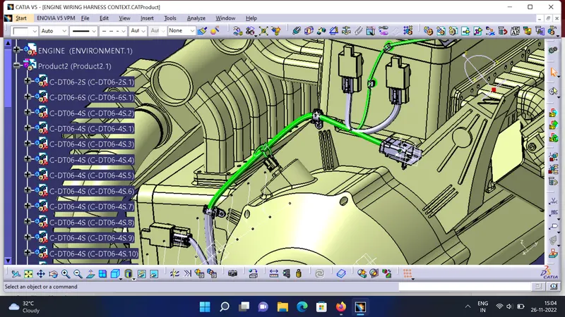
we are routing the bundle segment from interconnection connector to 3 P-clamps. The diameter for this routing path is 12mm and bend radius ratio is assumed to be 1.4
STEP 8
ADDING BRANCH POINT AND ROUTE ALL THE WIRING HARNESS
here we adding all the vital branching point and route all the remaining wiring harness.
STEP 9
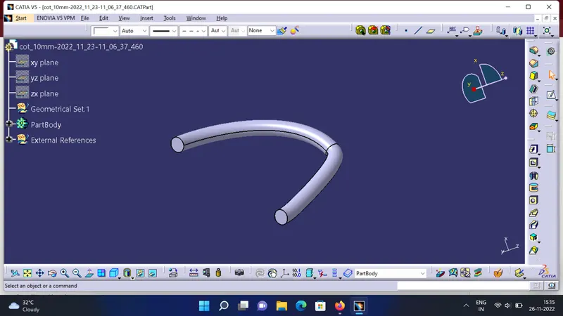
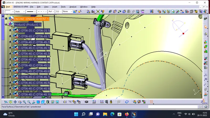
ADDING PROTECTIVE COVERING TO THE BUNDLES
STEP 10
CHECKING THE BUNDLE CONTINUITY
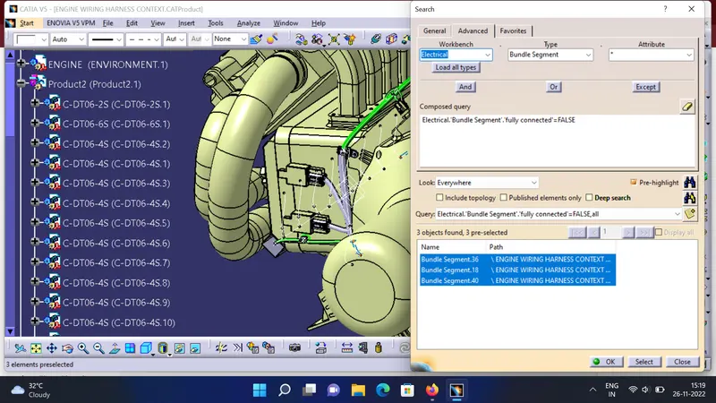
first we have to make sure that multi-branchable is selected then we have to go in Edit>Search>Advanced>Workbench-Electrical>Type-Bundle Segment>Attribute-Fully Connected. By selecting 'True' option will show all the connected bundle segments while selecting 'False' option will show all the non-connected bundle segments. we have selected for the 'True' option and searched for results. All the bundle segments are highlighted found showing that all the bundle segments are electrically connected as shown in below figure.
STEP 11
CREATING FLATTEN VIEW OF THE ENGINE HARNESS GEOMETRICAL BUNDLE ASSEMBLY
for creating flatten view we have to work in Electrical Harness Flattening workbench of Catia V5. We should also make sure that the flattening file is saved in the same folder where other files of harness assembly are saved. 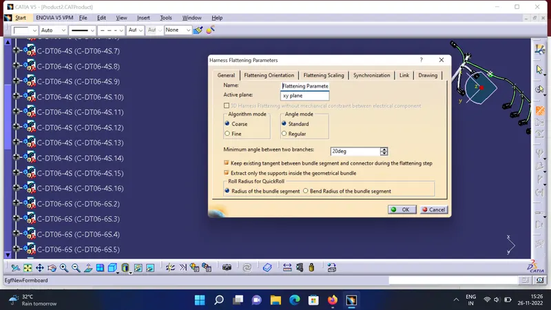
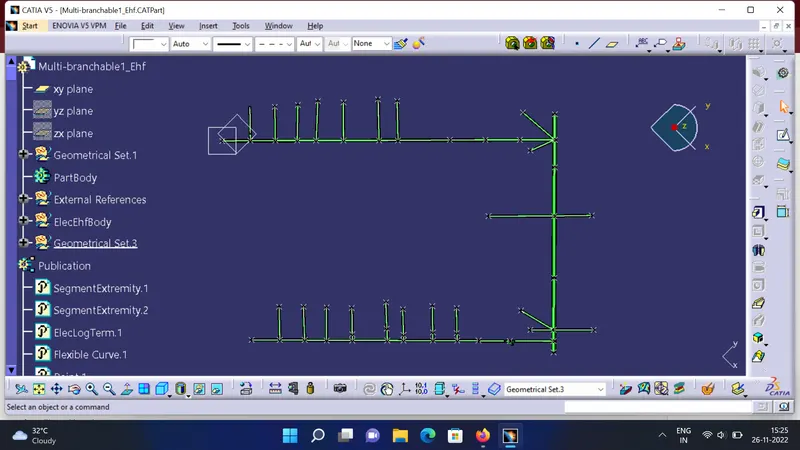
STEP 12
CREATING FLATEN VIEW DRAWING FOR WIRING HARNESS
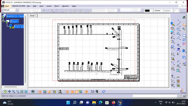
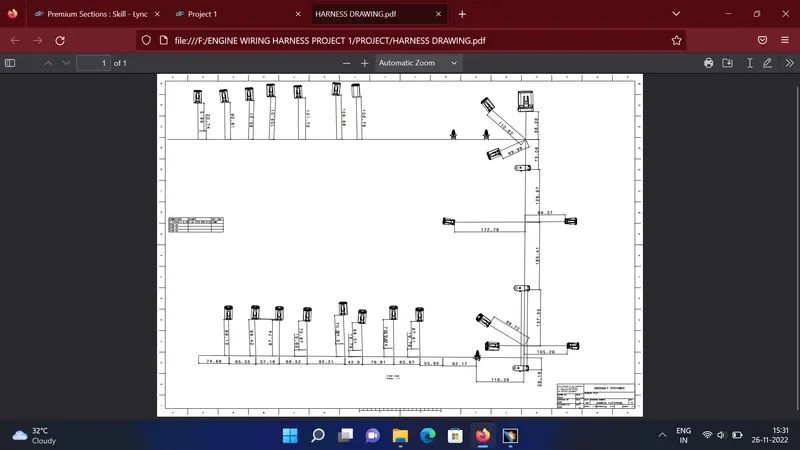
we are creating new drawing file and defined all the necessary drawing parameters. We have to insert the front view of the Engine Harness Flattening Product file into the Drawing file.
CONCLUSION
the engine wiring harness is succesfully routed by the best of industrial standards and created wiring harness drawing and saved as pdf.