Powertrain for aircraft in runways | Simulink
AIM : To design an electric powertrain for aircraft in runways and list out the theoretical information about aircrafts.
OBJECTIVES :
- To list out the total weight of various types of aircrafts.
- To find difference between ground speed and air speed of an aircraft.
- To find out why it is not recommended to use aircraft engine power to move it on the ground at Airport.
- To find out how an aircraft is pushed to runway when its ready to take off.
- To learn about take-off power, tyre design, rolling resistance, tyre pressure, brake forces when landing.
- To calculate the force and power required to push or pull an aircraft by a towing vehicle.
- To design an electric powertrain with type of motor, it’s power rating, and energy requirement to fulfil aircraft towing application and estimate the duty cycle range to control the aircraft speed from zero to highest.
1. Search and list out the total weight of various types of aircrafts.
There are different types of weights of an Aircraft which are,
- Operating Empty Weight (OEW) – It is the basic weight of an aircraft including the crew, all fluids necessary for operation such as engine oil, engine coolant, water, unusable fuel and all operator items and equipment required for flight but excluding usable fuel and the payload.
- Aircraft Gross Weight – The aircraft gross weightis the total aircraft weight at any moment during the flight or ground operation. An aircraft's gross weight will decrease during a flight due to fuel and oil consumption. An aircraft's gross weight may also vary during a flight due to payload dropping or in-flight refuelling. At the moment of releasing its brakes, the gross weight of an aircraft is equal to its take-off weight.
- Payload Weight – Payloadis the carrying capacity of an aircraft or launch vehicle, usually measured in terms of weight. Depending on the nature of the flight or mission, the payload of a vehicle may include cargo, passengers, flight crew, scientific instruments or experiments, or other equipment. Extra fuel, when optionally carried, is also considered part of the payload.
- Zero Fuel Weight – The zero-fuel weightof an aircraft is the total weight of the airplane and all its contents, minus the total weight of the usable fuel on board. Unusable fuel is included in Zero Fuel Weight.
- Maximum Take-off weight(MTOW) – It is the maximum weight of an aircraft at which the pilot is allowed to attempt to take off, due to structural or other limits. MTOW is the heaviest weight at which the aircraft has been shown to meet all the airworthiness requirements applicable to it. MTOW of an aircraft is fixed and does not vary with altitude, air temperature, or the length of the runway to be used for take-off or landing.
- Maximum Landing weight(MLW) – This is the maximum weight at which an aircraft is permitted to land on ground and without compromising airframe strength.
Generally aircrafts include Operating Empty Weight (OEW), Maximum Take-off weight (MTOW) and sometimes Maximum Landing weight (MLW) too. So we will categorize weights of different types of aircrafts according to them.
|
AIRCRAFT |
OEW (kg) |
MTOW (kg) |
MLW (kg) |
|
Passenger Aircrafts |
|||
|
Airbus A380-800 |
276,800 |
575,000 |
394,000 |
|
Airbus A350-900 |
115,700 |
270,000 |
175,000 |
|
Airbus A340-200 |
130,200 |
253,500 |
181,000 |
|
Airbus A321-100 |
48,500 |
83,000 |
77,800 |
|
Airbus A320-100 |
42,600 |
68,000 |
66,000 |
|
Airbus A318 |
39,500 |
59,000 |
57,500 |
|
Boeing B87-8 |
119,950 |
228,000 |
172,365 |
|
Boeing B747-400 |
183,500 |
396,900 |
295,742 |
|
Boeing B777-300 |
160,530 |
299,370 |
237,683 |
|
Boeing B737-800 |
41,145 |
79,000 |
65,320 |
|
Douglas DC-7 |
33,005 |
55,000 |
- |
|
Concorde |
78,700 |
185,000 |
111,100 |
|
Fighter / Military Aircrafts |
|||
|
Sukhoi(su-30mki) |
18,400 |
38,800 |
- |
|
Dassault Rafel |
9,979 |
24,500 |
- |
|
Mig 29 |
11,000 |
18,000 |
- |
|
Lockheed C-5 Galaxy |
172,365 |
381,000 |
288,417 |
|
HAL Tejas |
6,560 |
13,500 |
- |
|
Helicopters |
|||
|
Mil V-12 |
69,100 |
105,000 |
- |
|
Boeing CH-47F |
11,148 |
22,680 |
- |
|
Eurocopter EC135 |
1,455 |
2,910 |
- |
2. Is there any difference between ground speed and air speed?
The relationship between airspeed and ground speed is fairly simple.
Airspeed of an Aircraft – Airspeed is simply the speed at which an aircraft is moving relative to the air it is flying in. As such, it’s also the speed at which the air is flowing around the aircraft’s wings. There are two types of air speed that the pilot needs to refer to.
Indicated Air Speed (IAS) – Indicated Air Speed is the measure of dynamic pressure that is experienced by the aircraft at a particular instant. IAS is an important parameter that decides the capability of the aircraft to remain airborne. The minimum IAS at which level flight is possible is called the stalling speed. There is also a maximum IAS which is defined for an aircraft based on the strength of the material used in construction. Therefore, the pilot needs to constantly refer to the IAS.
True Air Speed (TAS) – True Air Speed is the exact speed at which the aircraft is travelling with respect to surrounding air. However, the air all around is always in motion. Due to the vector addition of the TAS and the wind velocity at that instant, the aircraft's travel will not be exactly in the direction towards which it is pointing and speed of the TAS.
Ground Speed of an Aircraft – Ground speed is the aircraft’s speed relative to the ground. One thing that should be noted here is that it’s its horizontal rather than vertical speed, an aircraft climbing completely vertically would have a ground speed of zero. Ground speed is simply the sum of airspeed and wind speed. The main use of an aircraft is to travel from place A to place B. To calculate the exact time that it would take to reach various locations enroute as well as the destination, there is a need to know the exact speed at which the aircraft is travelling with respect to the ground as well as the direction in which is travelling. That is the ground speed.
While airspeed is what determines whether there is enough airflow around an aircraft to make it fly, ground speed is what determines how fast an aircraft will get to its destination. If the aircraft is flying in the same direction as the wind is blowing, the aircraft experiences tailwind, and its ground speed is higher than its airspeed. On the other hand, if the wind is blowing against the direction the aircraft is traveling in, the aircraft experiences headwind, and its ground speed is lower than its airspeed.
This is why some flights go out of their way to avoid headwinds or catch tailwinds. And, why some flights might appear to be traveling at supersonic speeds, even though their airspeed the speed that would actually matter in determining whether or not the flight truly is supersonic is subsonic.
For pilots, both airspeed and ground speed are very important. While the first of those helps them make sure they are flying fast enough to take off, not to stall, and so on, the second one helps them figure out how long it will take them to get from one place to another. The passengers only need to be concerned about the ground speed as that will tell them how fast they are flying from origin to their destination.
3. Why is it not recommended to use aircraft engine power to move it on the ground at Airport?
Generally aircrafts move with the help of Engine power on the ground at airport. The difference being that the engine power is not used at its full performance as obtained during the flight of the aircraft. The engine is operated under throttle 1 condition which uses engine power to obtain less speed.
Sometimes it is not recommended to use the engine power to move the aircraft on the ground at Airport. There are multiple reasons for this one of which is that there are a lot of things as well as airport crew members surrounding the aircraft. If the aircraft uses its engine power in such an environment, the engine turbine or fan may suck or throw the surrounding objects, trash or even human beings which are accidental.
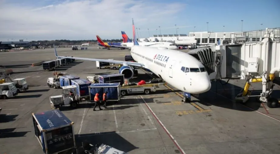
The air intake of a jet engine is powerful enough to suck in a human body. Even at a distance, the jet engine suction is strong enough to devour loose debris e.g., rags, bolts, paper, stones, catering foils, plastic cups and bags. All these will damage the jet engine. In case of Jet exhaust, the temperatures of the exhaust can severely burn the skin of a person standing too close. The jet blast or prop wash can exceed 100 mph and is capable of moving or toppling heavy persons or equipment.
Other reasons being the noise of the engine which are at very high decibels as well as the fumes emitted by the burning of the fuel, the fuel consumption of an aircraft and also the risk of damage to the engine due to foreign objects.
4. How an aircraft is pushed to runway when it’s ready to take off?
There are two ways through which an aircraft is pushed to the runway on Airport.
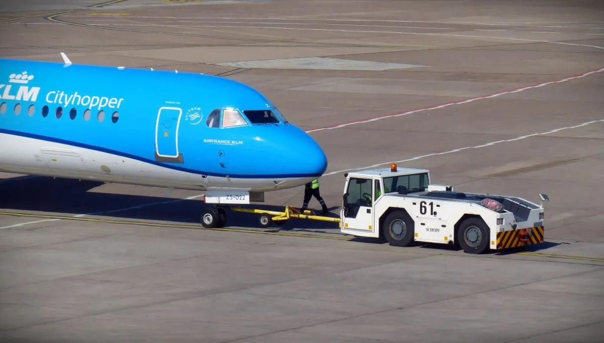
Pushback – In aviation, pushback is an airport procedure during which an aircraft is pushed backwards away from an airport gate by external power. Pushbacks are carried out by special, low-profile vehicles called pushback tractors or tugs.
Although many aircraft are capable of moving themselves backwards on the ground using reverse thrust (a procedure referred to as a power back), the resulting jet blast or prop wash might cause damage to the terminal building or equipment. Engines close to the ground may also blow sand and debris forward and then suck them into the engine, causing damage to the engine. A pushback is therefore the preferred method to move the aircraft away from the gate. Closer to departure, an aircraft tug will park right in front of the nose wheel.
The tug might be directly attached to the plane's nose gear with a tow bar, or could be a wheel-lift tug. These tugs cradle the nose gear, then lift it up before moving the plane. That gives the tug driver control over the plane's direction during pushback. New taxi technologies are appearing, like pilot-controlled tugs, and electric motors mounted to the plane's landing gear. Both promise to save fuel, and reduce airport noise. When the aircraft is stopped, the brakes of the towing vehicle alone should not be relied upon to stop the aircraft. The man in the cockpit should coordinate the use of the aircraft brakes with those of the towing vehicle.
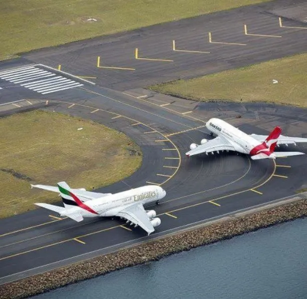
Taxiing – Taxiing is the movement of an aircraft on the ground, under its own power, in contrast to towing or push-back where the aircraft is moved by a tug. The aircraft usually moves on wheels, but the term also includes aircraft with skis or floats for water-based travel. An airplane uses taxiways to taxi from one place on an airport to another; for example, when moving from a hangar to the runway.
The term taxiing is not used for the accelerating run along a runway prior to take-off, or the decelerating run immediately after landing, which is called the take-off roll and landing rollout, respectively. When taxiing, aircraft travel slowly. This ensures that they can be stopped quickly and do not risk wheel damage on larger aircraft if they accidentally turn off the paved surface. Taxi speeds are typically 30 to 35 km/h.
5. Learn about take-off power, tyre design, rolling resistance, tyre pressure, brake forces when landing.
Take-Off Power :
Take-off (T-O) is the phase of flight in which an aerospace vehicle leaves the ground and becomes airborne. For aircraft that take off horizontally, this usually involves starting with a transition from moving along the ground on a runway. For light aircraft, usually full power is used during take-off. Large transport category aircraft may use a reduced power for take-off, where less than full power is applied in order to prolong engine life, reduce maintenance costs and reduce noise emissions.
The aircraft is permitted to accelerate to rotation speed. The term rotation is used because the aircraft pivots around the axis of its main landing gear while still on the ground, usually because of gentle manipulation of the flight controls to make or facilitate this change in aircraft attitude and once proper air displacement occurs under or over the wings, an aircraft will lift off on its own.
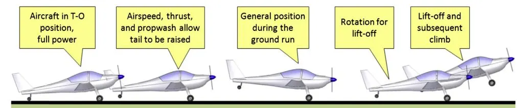
Generally, the T-O phase is split into the segments shown in the figure below. The ground roll is the distance from brake release to the initiation of the rotation, when the pilot pulls the control wheel (or stick or yoke) backward in order to raise the nose of the aircraft. This maneuver is required to increase the area of attack of the airplane to help it become airborne. The aircraft typically remains in this attitude for some 1-3 seconds, depending on aircraft size, before the tires lose contact with the ground. This segment is called the rotation. The rotation phase concludes as the aircraft lifts off the ground and begins the transition and subsequent climb phase.
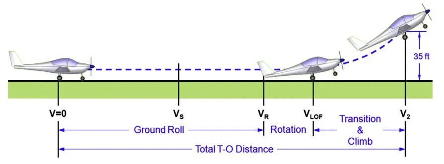
Here V is the instantaneous airspeed of the aircraft, VR is the ground run speed, VLOF is the lift off for rotation speed, V2 is the climb speed and VS is the stalling speed in the T-O configuration. This means that if the airplane features high-lift devices, VS refers to the stalling speed with flaps deployed. The important point is that the airplane must accelerate from standstill to a given airspeed, called the lift-off speed, before it can, well, lift off.
Generally the take of speed or the climb speed of the aircraft (V2) is calculated as,
`V_2=1.2V_S`
Where the stalling speed at the Take-Off configuration is given as,
`V_S=√(2W)/(ρSC_(L,max) )`
In the above equation, ‘W’ is the gross weight of the aircraft, ‘`rho`’ is the free stream density of air, ‘S’ is the wing area of the aircraft and ‘CL,max’ is the maximum lift coefficient.
The take-off speed required varies with aircraft weight and aircraft configuration; the heavier the weight, the greater the speed needed. Typical take-off air speeds for jetliners are in the range of 240 - 285 km/h, light aircraft take off at around 100 km/h and ultra lights have even lower take-off speeds.
Tyre Design :
An aircraft tire or tyre is designed to withstand extremely heavy loads for short durations. The number of tires required for aircraft increases with the weight of the aircraft, as the weight of the airplane needs to be distributed more evenly. Aircraft tire tread patterns are designed to facilitate stability in high crosswind conditions, to channel water away to prevent hydroplaning, and for braking effect.
Aircraft tires may be tube-type or tubeless. They support the weight of the aircraft while it is on the ground and provide the necessary traction for braking and stopping. The tires also help absorb the shock of landing and cushion the roughness of take-off, rollout, and taxi operations. Aircraft tires must be carefully maintained to perform as required. They accept a variety of static and dynamic stresses and must do so dependably in a wide range of operating conditions.
Bias-ply tires are popular choices for aircraft tires because of their durability and retreadability. The tire construction consists of the following components.
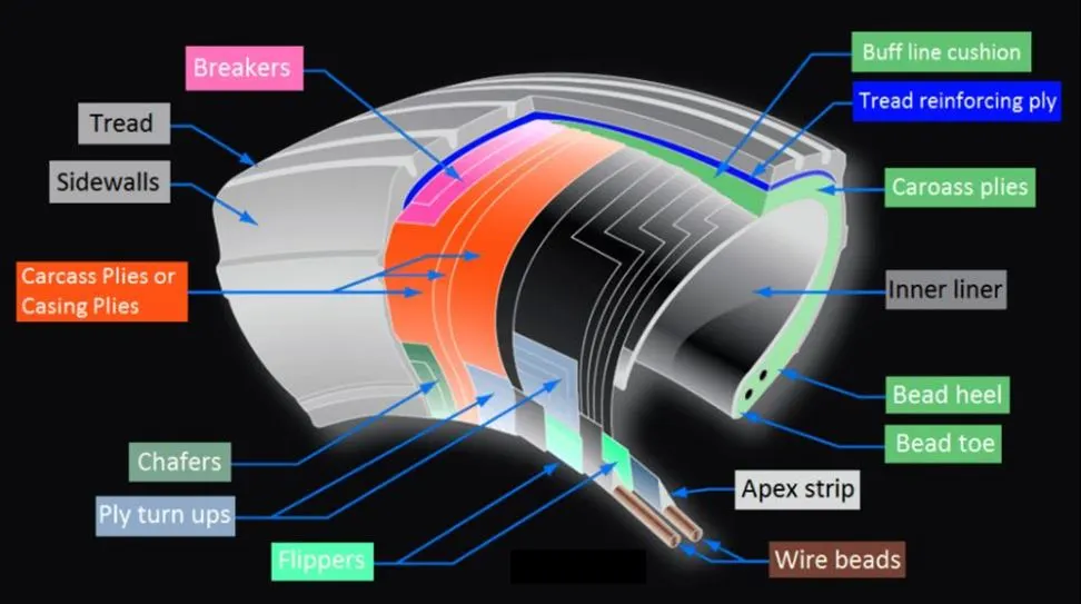
Tread – The tread is made of rubber mixed with other additives to obtain the desired level of toughness, durability, and resistance to wear. The tread pattern is designed to aircraft operational requirements, with the ribbed tread design used widely due to its good traction under varying runway conditions.
Sidewall – The sidewall is a protective layer of rubber that covers the outer casing ply. It extends from the tread edge to the bead area.
Tread Reinforcing Ply – One or more layers of fabric that strengthens and stabilizes the tread area for high-speed operation. It also serves as a reference for the buffing process when tires are retreaded.
Buff Line Cushion – The buff line cushion is made of rubber compound to enhance the adhesion between the tread reinforcing ply and the breakers or casing plies. It is of sufficient thickness to allow for the removal of the old tread when the tire is retreaded.
Breakers – Breakers are reinforcing plies of rubber-coated fabric placed under the buff line cushion to protect casing plies and strengthen and stabilize the tread area. They are considered an integral part of the casing construction.
Casing Plies – Alternate layers of rubber-coated fabric (running at opposite angles to one another) provide the strength of the tire.
Wire Beads – Hoops of high tensile strength steel wire that anchor the casing plies and provides a firm mounting surface on the wheel. The outer edge of the bead that fits against the wheel flange is called the bead heel. The inner bead edge is called the bead toe.
Apex Strip – A wedge of rubber affixed to the top of the bead bundle.
Flippers – Layers of rubberized fabric that help anchor the bead wires to the casing and improve the durability of the tire.
Ply Turn ups – The casing plies are anchored by wrapping them around the wire beads, thus forming the ply turn ups.
Chafer – A protective layer of rubber and/or fabric located between the casing plies and wheel to minimize chafing.
Liner – In tubeless tires, the liner is a layer of low permeability rubber that acts as a built-in tube and restricts gas from diffusing into the casing plies. In tube-type tires, a thinner liner is used to prevent tube chafing against the inside ply.
Tyre Pressure :
Aircraft tires generally operate at high pressures, up to 200 psi (14 bar; 1,400 kPa) for airliners, and even higher for business jets. Tests of airliner aircraft tires have shown that they are able to sustain pressures of maximum 800 psi (55 bar; 5,500 kPa) before bursting. During the tests the tires have to be filled with water, to prevent the test room being blown apart by the energy that would be released by a gas when the tire bursts.
Aircraft tires are usually inflated with nitrogen to minimize expansion and contraction from extreme changes in ambient temperature and pressure experienced during flight. Dry nitrogen expands at the same rate as other dry atmospheric gases (normal air is about 80% nitrogen), but common compressed air sources may contain moisture, which increases the expansion rate with temperature.
The requirement that an inert gas, such as nitrogen, be used instead of air for inflation of tires on certain transport category airplanes was prompted by at least three cases in which the oxygen in air-filled tires had combined with volatile gases given off by a severely overheated tire and exploded upon reaching auto ignition temperature. The use of an inert gas for tire inflation eliminates the possibility of tire explosion.
Rolling Resistance :
Rolling resistance, sometimes called rolling friction, is the force resisting the motion when a body rolls on a surface. During the ground roll of the aircraft, rolling friction is one of the forces which is experienced by the aircraft. The friction force will be gradually decreasing to zero at lift-off. The friction force is proportional to the normal component NL of the reaction of the surface and is given as,
`F_f=μN_L`
Where, μ is a constant called the static rolling friction coefficient. The normal force is the algebraic sum of the aircraft weight WL and aerodynamic lift LL.
`F_f=μ(W_L-L_L )`
Although at any given instant the point of a rolling wheel in contact with the ground has no relative motion with respect to the ground, the wheel eliminates the large friction forces that would arise if the fuselage were in direct contact with the ground. However, there is some friction to the wheels rolling for two reasons, one of which is that each wheel has an axle or bearing that has a minor friction. Other reason is that there is a small area deformation of the wheel, so the contact will take place over a certain area rather than a point.
This area is a function of the aircraft weight, tire internal pressure, and air temperature. As the aircraft weight is increased, the friction area is increased, whereas if the internal tire pressure is increased, the friction area is decreased. This is referred to as the rolling friction or rolling resistance. Due to the complex nature of this friction and parameters involved, the exact values for the rolling coefficient have not been clearly deduced. The range of values for the surface of a runway is due to the quality of the surface and its age. The quality of a new asphalt runway is much better than that for an older asphalt runway, as it has a lower friction coefficient.
Brake forces when landing :
One of the effective parameters influencing landing run is the brake force, while it is ineffective during take-off operation. The landing phases of an aircraft are shown below.
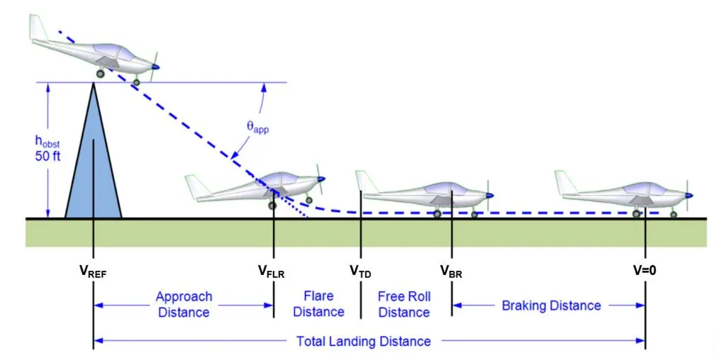
The airspeed during approach is decreased by increasing the angle of attack, but airspeed during ground roll is decreased by applying brakes. The mechanical brakes present at the wheels are of two common kinds; drum brakes and disc brakes. Drum brakes usually reside inside the wheel, which reduces their frontal area and, if mounted on retractable landing gear, makes them a possible solution for space-claim issues in thin wings. Disc brakes have superior performance, are lighter, and easier to maintain.
The brake force is sometimes reinforced with other means such as parachute, engine thrust reversal, hook and string, and spoiler. These factors will reduce the landing run. The maximum aircraft angle of attack during landing is often 2°–4° less than the maximum aircraft angle of attack during take-off (e.g., 10°–15°). To compensate for this angle of attack reduction, a higher flap detection is employed. In most cases, flap detection during landing is between 30° and 60°, while during take-off it is between 5° and 30°.
6. With necessary assumptions, calculate the force and power required to push / pull an aircraft by a towing vehicle.
Airliners are often pushed back by a tug or a tractor to leave the gate. The tug can also tow an aircraft that cannot taxi by itself. Tugs do not need that much horsepower to tow the aircraft, even the biggest tugs only have around 400 bhp. What they do need is lots of torque for push/pull power, lots of weight to give it plenty of inertia, and big tires to transfer the power to the surface.
To proceed for calculating the force and power required to push or pull an aircraft by a towing vehicle, we will assume the following parameters;
Here we will consider aircraft and towing vehicle as separate units. We will also consider three forces acting on aircraft as well as towing vehicle which are; Rolling Friction Force, Acceleration Force and Aerodynamic Drag force. We will neglect the all the losses for calculations.
Aircraft Calculations :
Mass of the aircraft, `m_A=50,000 kg`
Rolling ground friction coefficient of wheels for Dry concrete or asphalt road, `μ_r=0.03`
Acceleration due to gravity, `g=9.81 ms^-2`
Frontal area or Wingspan area of an aircraft, `A_A=85 m^2`
Final Velocity of an aircraft, `v_A=3 ms^(-1)`
Initial Velocity of an aircraft, `u_A=0 ms^(-1)`
Coefficient of drag of an aircraft, `C_(dA)=0.017`
Density of air, `ρ=1.225 kgm^-3`
Acceleration time of aircraft, `t_A=10 s`
Rolling Resistance Force –
`F_(RA)=μ_r m_A g`
`F_(RA)=0.03×50000×9.81`
`F_(RA)=14715 N`
The rolling resistance force between aircraft wheels and tarmac road is 14715 N.
Acceleration Force –
`F_(A A)=m_A a`
`F_(A A)=m_A ((v_A-u_A)/t_A )`
`F_(A A)=50000×((3-0)/10)`
`F_(A A)=15000 N`
The acceleration force of the aircraft is 15000 N
Aerodynamic Drag Force –
`F_(DA)=0.5×ρ×A_A×v_A^2×C_(dA)`
`F_(DA)=0.5×1.225×85×10^2×0.017`
`F_(DA)=88.50 N`
The aerodynamic drag force experienced by an aircraft when it moves on the ground is 88.50 N.
Towing Vehicle Calculations –
Mass of the towing vehicle, `m_T=8,000 kg`
Rolling ground friction coefficient of wheels for Dry concrete or asphalt road, `μ_r=0.013`
Acceleration due to gravity, `g=9.81 ms^-2`
Frontal area of towing vehicle, `A_T=8 m^2`
Final Velocity of an aircraft, `v_T=3 ms^(-1)`
Initial Velocity of an aircraft, `u_T=0 ms^(-1)`
Coefficient of drag of an aircraft, `C_(dT)=0.62`
Density of air, `ρ=1.225 kgm^-3`
Acceleration time of aircraft, `t_T=10 s`
Rolling Resistance Force –
`F_(RT)=μ_r m_T g`
`F_(RT)=0.013×8000×9.81`
`F_(RT)=1020.24 N`
The rolling resistance force between towing vehicle’s wheels and tarmac road is 1020.24 N.
Acceleration Force –
`F_(AT)=m_T a`
`F_(AT)=m_T ((v_T-u_T)/t_T )`
`F_(AT)=8000×((3-0)/10)`
`F_(AT)=2400 N`
The acceleration force of the aircraft is 2400 N
Aerodynamic Drag Force –
`F_(DT)=0.5×ρ×A_T×v_T^2×C_(dT)`
`F_(DT)=0.5×1.225×8×10^2×0.62`
`F_(DT)=303.80 N`
The aerodynamic drag force experienced by an aircraft when it moves on the ground is 303.80 N.
Now, to calculate the power required to push/pull the aircraft by a towing vehicle, we need to find the total tractive force by adding all the forces obtained.
Total Tractive Force :
`F_T=F_(RA)+F_(RT)+F_(A A)+F_(AT)+F_(DA)+F_(DT)`
`F_T=14715+1020.24+15000+2400+88.50+303.80`
`F_T=33527.54 N or 33.527 kN`
So the total tractive force needed is 33527.54 N or 33.527 kN.
Power required to push/pull the aircraft :
`P=F_T.v`
`P=33527.54×3`
`P=100582.62 W or 100.58 kW`
So, the total power required to push/pull the aircraft by the towing vehicle is 100.58 kW or 135 bhp.
7. Design an electric powertrain with type of motor, it’s power rating, and energy requirement to fulfil aircraft towing application. Estimate the duty cycle range to control the aircraft speed from zero to highest. Make required assumptions. Prepare a table of assumed parameters. Draw a block diagram of powertrain.
We will take the above results for our further calculations. So we know that the total power required to push/pull the aircraft by the towing vehicle is 100.58 kW and the total tractive force needed is 33527.54 N. Now, we can calculate the torque needed by the towing vehicle by assuming the following parameters,
Radius of the wheel of towing vehicle, `r=0.4 m`
Gear ratio, `G=10`
Torque, `T=(F_T.r)/G`
`T=(33527.54×0.4)/10`
`T=1341.10 Nm`
The torque required for the towing vehicle to push/pull the aircraft is 1341.10 Nm.
To design the electric powertrain of towing vehicle we need to select the motor based on power rating as well as the battery required based on energy requirement and duty cycle range to control the aircraft speed from zero to highest.
Motor –
We need to select a motor with power rating as 100.58 kW and Torque 1341.10 Nm. We will select TECO IE2 Electric Induction motor which has 110 kW power output and torque at full load is 1420 Nm which satisfies the power output and torque needed for our vehicle.
Motor Specification :
Output Power – 110 kW, 150 hp
Full Load Speed – 740 rpm
Full Load Efficiency – 94.5%
Full Load Current – 210 A
Full Load Torque – 1420 Nm
Rated Voltage – 400 V/50 Hz
Duty Cycle –
As we have the rated voltage as 400 V, we can assume the current to be 300 A as current value can exceed the full load current of the motor. Thus, we can calculate the Input Power (Pi) of the motor which is the product of Voltage (V) and Current (I).
`P_i=V.I`
`P_i=400×300`
`P_i=120000 W or 120 kW`
We have input power as well as the output power. Thus we can calculate the Duty Cycle (`delta`) which is the ratio of Output Power (Po) and Input Power (Pi).
`δ=P_o/P_i`
`δ=(100.58 )/(120 )`
`δ=0.838 or 83.8%`
Energy –
Now we have to calculate the Energy required from the Batteries or Battery pack. The Energy (E) required is the product of Output Power (Po) and Time (t). For our calculations, we will consider the battery usage for 5 minutes that is 300 seconds.
`E=P_o .t`
`E=100.58×300`
`E=30174 kJ`
So the battery pack should provide 30174 kJ of energy to the vehicle. Generally batteries are rated in kilowatt hour (kWh). So we will convert kJ to kWh by dividing 3600.
`E=30174/3600`
`E=8.38 kWh`
So the battery pack should provide atleast 8.38 kWh to the vehicle.
|
PARAMETER |
ASSUMED VALUE |
|
Radius of the wheel of towing vehicle |
0.4 m |
|
Gear ratio |
10 |
|
Input Current to motor |
300 A |
Note : The motor values were taken from the manufacturer’s catalogue which is given below.
http://www.teco.com.tw/fa/ecatalogue_file/en/(Europe)StandardIE2IE3MotorCatalogueAESV-AESU.pdf
|
OBTAINED PARAMETER |
RESULT |
|
Required Torque Output of motor |
1341.10 Nm |
|
Input Power of the motor |
120 kW |
|
Duty Cycle range |
83.8% |
|
Energy required from batteries |
8.38 kWh |
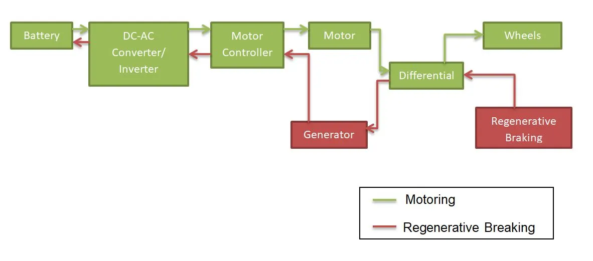
Towing Vehicle Simulink Powertrain Block Diagram :
CONCLUSION :
The study and research of various aspects and concepts of an Aircraft has been studied and reported. The types of forces, required power, required motor, required energy and duty cycle for a towing vehicle is calculated with all necessary assumptions and the block diagram of Simulink Powertrain is prepared.
Link to Google Drive of doc file for Simulink Powetrain Block Diagram - https://drive.google.com/file/d/1mzfQnMmT-IL0X7eBr5LNHeHB23ysYG6M/view?usp=sharing