POWERTRAIN FOR AIRCRAFT IN RUNWAYS
AIM:
- To list out the weights of various aircrafts
- Calculate the force & power required to pull/push an aircraft by a towing vehicle.
- Design an electric powertrain with type of motor, it’s power rating, and energy requirement to fulfill aircraft towing application.
EXPLANATION:
An aircraft's gross weight is limited by several weight restrictions in order to avoid overloading its structure or to avoid unacceptable performance or handling qualities while in operation.Aircraft gross weight limits are established during an aircraft's design and certification period and are laid down in the aircraft's type certificate and manufacturer specification documents.The absolute maximum weight capabilities of a given aircraft are referred to as the structural weight limits.
Some of the weight characteristics are,
Maximum design taxi weight (MDTW):
The maximum design taxi weight (also known as the maximum design ramp weight (MDRW)) is the maximum weight certificated for aircraft manoeuvring on the ground (taxiing or towing) as limited by aircraft strength and airworthiness requirements.
Maximum design takeoff weight (MDTOW):
It is the maximum certificated design weight when the brakes are released for takeoff and is the greatest weight for which compliance with the relevant structural and engineering requirements has been demonstrated by the manufacturer.
Maximum design landing weight (MDLW):
The maximum certificated design weight at which the aircraft meets the appropriate landing certification requirements. It generally depends on the landing gear strength or the landing impact loads on certain parts of the wing structure.
The MDLW must not exceed the MDTOW.
Maximum design zero-fuel weight (MDZFW):
The maximum certificated design weight of the aircraft less all usable fuel and other specified usable agents (engine injection fluid, and other consumable propulsion agents). It is the maximum weight permitted before usable fuel and other specified usable fluids are loaded in specified sections of the airplane. The MDZFW is limited by strength and airworthiness requirements. At this weight, the subsequent addition of fuel will not result in the aircraft design strength being exceeded. The weight difference between the MDTOW and the MDZFW may be utilised only for the addition of fuel.
Minimum flight weight (MFW):
Minimum certificated weight for flight as limited by aircraft strength and airworthiness requirements.
Some examples are,
|
Difference between Air speed & Ground speed:
Aerodynamic forces are generated by an object moving through a fluid. A fixed object in a static fluid does not generate aerodynamic forces.So, to generate Aerodynamic lift, an object must move through the air, or air must move past the object. Aerodynamic lift depends on the square of the velocity between the object and air.
To define the relative velocity,we pick a reference point and measure relative velocities to it.
To measure the relative velocity,We consider three factors.
1.Wind speed:
For a reference point picked on the ground, the air moves relative to the reference point at the wind speed.Wind speed is a vector quantity.So the direction of wind is ver much important.
2.Ground speed:
For a reference point picked on the ground, the aircraft moves relative to the reference point at the ground speed.It is also a vector quantity.A tailwind is a wind that blows in the direction of travel of an object, while a headwind blows against the direction of travel. A tailwind increases the object's speed and reduces the time required to reach its destination, while a headwind has the opposite effect.
3.Air speed:The important quantity in the generation of lift is the relative velocity between the object and the air, which is called the airspeed. Airspeed cannot be directly measured from a ground position, but must be computed from the ground speed and the wind speed. Airspeed is the vector difference between the ground speed and the wind speed.
Airspeed = Ground Speed - Wind Speed
On a perfectly still day, the airspeed is equal to the ground speed. But if the wind is blowing in the same direction that the aircraft is moving, the airspeed will be less than the ground speed.
In aeronautics, a headwind is favorable in takeoffs and landings because an airfoil moving into a headwind is capable of generating greater lift than the same airfoil moving through tranquil air, or with a tailwind, at equal ground speed. As a result, aviators and air traffic controllers commonly choose to take off or land in the direction of a runway that will provide a headwind.
So, is it not recommended to use aircraft engine power to move it on the ground at Airport?
In most of the cases,NO.using an aircraft engine causes
- Fuel consumption.
- Wear and tear on the engine.
- Unnecessary jet blast and noise.Jet blast is the phenomenon of rapid air movement produced by the jet engines of aircraft.
- Results in propwash or slipwash
- FOD,Foreign Object Debris:Foreign substances such as sand which potentially causes damage to the aircraft engine.
How to overcome these problems?How an aircraft is pushed to runway when its ready to take off?
Here we use the Pushback method,aircraft is pushed to the runway by vehicles called tugs or tractors.This method is also callled as Taxiing.Some Airplanes are capable of producing reverse thrusts.But these methods are not recommended as FOD may cause severe damages to the thrust engine.
TAKE-OFF POWER:
Take-off power is the power required for an airplane to become airbourne.
There will be 4 forces acting on an airplane during take-off.They are,Thrust,lift,Drag and Gravity.
Thrust is the forward motion created by the engine where drag is its opposing force i.e. air resistance. Lift is an upward motion created by deflecting airflows and weight is considered as the opposing force by its self mass with gravity.So when the thrust is increased with the required velocity or airspeed by adjusting wings for lift so that airplane takes off.That Power is defined as Take-off Power.
TYRE DESIGN:
An aircraft tyre is designed to withstand extremely heavy loads for short durations. The number of tires required for aircraft increases with the weight of the aircraft, as the weight of the airplane needs to be distributed more evenly. Aircraft tire tread patterns are designed to facilitate stability in high crosswind conditions, to channel water away to prevent hydroplaning, and for braking effect.
Aircraft tires are usually inflated with nitrogen to minimize expansion and contraction from extreme changes in ambient temperature and pressure experienced during flight.
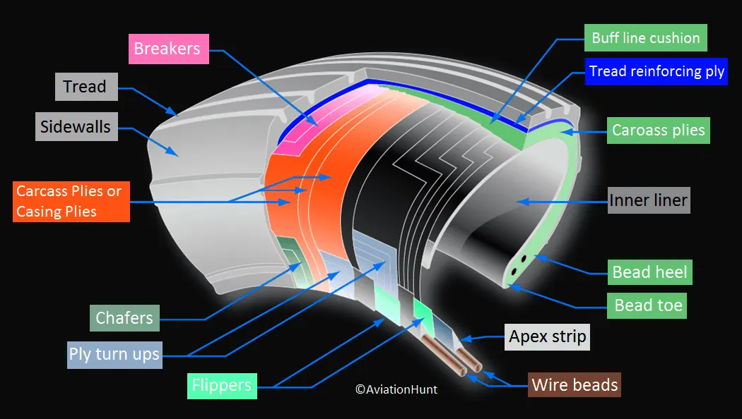
Retreading – Retreading is methods of restoring a worn tyre by renewing the tread area or by renewing the tread area plus one or both sidewalls. Repairs are included in the tyre retreading process.
Load Rating – Load rating is the maximum permissible load at a specified inflation pressure.
Ply Rating – Ply Rating is used to identify the maximum recommended load rating and inflation pressure for a specified tyre. It is an index of tyre strength.
Speed Rating – The speed rating is the maximum takeoff speed to which the tyre has been tested.
Skid Depth – Skid depth is the distance between the tread surface and the deepest groove as measured in the mould.
Tubeless tyres are more advantageous over tube-type. There is no longer the use of tube-type tyre in recent aviation. Nowadays all airliners are using tubeless tyres. Tubeless that are meant to be used without a tube has the word TUBELESS on the sidewall of the tyre.
Rolling resistance:
Rolling resistance is the combination of forces that work against the forward motion of an aircraft during Take-off and landing.
It is given by
`F_(rr)=mu_(rr)mg`
where,
`mu_(rr)=0.01(1+0.001v)` for less than <128km/hr
Tyre pressure:
Aircraft tires generally operate at high pressures, up to 200 psi (14 bar; 1,400 kPa) for airliners, and even higher for business jets.
Tests of airliner aircraft tires have shown that they are able to sustain pressures of maximum 800 psi (55 bar; 5,500 kPa) before bursting.
Aircraft tires are usually inflated with nitrogen to minimize expansion and contraction from extreme changes in ambient temperature and pressure experienced during flight.Dry nitrogen expands at the same rate as other dry atmospheric gases (normal air is about 80% nitrogen), but common compressed air sources may contain moisture, which increases the expansion rate with temperature.
Brake forces while landing:
Aircraft brakes stop a moving aircraft by converting its kinetic energy to heat energy by means of friction between rotating and stationary discs located in brake assemblies in the wheels.
Brakes provide this critical stopping function during landings to enable airplanes to stop within the length of the runway.Brakes are applied to slowdown the wheels.This has the opposite effect on the wheel rotation: they are not forced to turn faster, but slower. This (+ friction) gives rise to decelerating force at the contact point with the road.
To calculate the force and power required to push / pull an aircraft by a towing vehicle:
For an assumed aircraft,
Total weight,m=50000kg
Frontal area,A=455m2(Including aircraft area)
moving at a maximum speed,v of 20kmph,i.e,20*1000/3600=5.55m/s
As the velocity is below 128kmph,
we can use the formula`mu_(rr)=0.01(1+0.001v)`
`mu_(rr)=0.01+(1+0.001*5.55)`
=0.01
Assume Drag coeeficient of Cd=0.021 & radius of tire,r=0.6m
As the surface of the runway is flat,hill climbing forces are not present.
so total tractive force becomes
`F_T=mu_(rr)mg+0.625AC_dv^2`
=0.01*50000*9.81+0.625*455*0.021*5.55^2
=5088.95N
Power,P=F*v
P=5088.95*5.55
P=28.24kW
Torque is given ,T=F*r
T=5088.95*0.6=3053.37N-m
Angular velocity,w=v/r=5.55/0.6=9.25rad/s
Torque required is very high in this application as its a heavy duty application.
Designing the powertrain,
Block diagram of E-towing tug
From the above calculation,
For a DC brushless machine,
Torque,T=3053N-m
Power=28.24kW
w=9.25rad/s
Energy required to fullfill the towing required is
E=P*t
If the towing operation is for 5 mins,
the total energy required is,
E=28.4*300/3600
E=2.35kWh
To find the lossess in a DC motor,we define
constants for copper losses,iron losses,windage losses constants as
kc=0.2
ki=0.008
kw=0.00001
constant losses=20
Copper losses=`k_c*T^2`
0.2*3053=610.6
Iron losses=`k_iw`
0.008*9.25=0.074
Windage losses=`k_ww^3`
=0.00001*9.25^3=0.007
constant losses=20
so ,
Input power =Output power+copper losses+iron losses+windage losses+constant losses
=28243+610.6+0.074+0.007+20=28870W=28.87kW
Efficiency=output power/input power
=28.24/28.87=0.97=97% of eeficiency is obtained.
Let us assume ,For a 400V battery at 75amps current,
P=V*I=400*75=30kW
for 28.24kW,keeping current same for a series circuit,
voltage,V=P/I
V☺=28240/75=376Volts
duty cycle=V☺/V_b
d=376/400=0.94
Duty cycle range will be from 0-94% for a 400V battery.
For an electrically operated towing tug ,A high torque, low speed motor is required with minimal losses.
REFERENCES: