Power Window System Using a Model-Based Design Approach
Aim:
Modeling, Simulating and Validating a Power Window System Using a Model-Based Design Approach
Introduction:
In the power window system, Direct Current (DC) motor served as the source of power to drive the power window
frame and accordingly power window can be raised and lowered. The mathematical model of a DC motor controlled by
an H bridge circuit and bridge is controlled through input switches which are available at driver and passenger door
side. The main objective of power window control is to control the movement of glass doors in upper and lower
direction and this operation is controlled with the help of a current sensor, fire sensor, and position sensor in the
replacement of manual control hand-turned crank techniques for existing power windows. The driving component is a
DC motor that drives the power window using self-locking techniques for worm gear in the minimum ratio of 1:50 and
the output of worm gear goes to a lead screw having a pitch of 3mm to deliver linear movement to the power window.
The control unit of the power window senses both high and low load obstructions. It is used to activate and deactivate
the movement of the glass door in the upward direction and downward direction with the help of a DC motor,
whenever, any hard and soft obstruction is detected. The automatic power window with intelligent control is designed
and verified with several conditions that claim its movement in an upward and downward direction. The simulation
model is visualized in MATLAB/Simulink and performance is analyzed.
Methodology:
System Requirements Analysis -
The Control System uses fault detection algorithms to protect the window hardware and any obstacles in the path of
the window. It also uses mode logic to decide when the window should be moved and in which direction.
The system design meets these performance requirements.
• The window must open or close completely within 5 sec.
• The motor must shut off after 5 sec of continuous movement in any direction. This requirement provides fail-safe
protection for the window mechanism, motor, and drive.
• The window must start moving no later than 0.2 sec after a command is issued.
• The window must stop when it reaches a fully opened or fully closed position.
• If the up or down command is issued for a duration of 0.2 sec to 1 sec, the window must be fully opened or
closed, unless interrupted by a new window command or an obstacle. This requirement represents the automatic-up
and automatic-down capability of the power window.
• The window must be able to detect an obstacle with a force less than 100 N. The window must be lowered by
approximately 10 cm if an obstacle is detected.
• Obstacle detection has priority over both driver-side and passenger-side controls. Driver-side controls have priority
over passenger-side controls.
Control System Design -
The following sections provide a description of the event-driven controller implemented in Stateflow. The following
the figure shows the complete high-level Stateflow chart.
Controller Input -
The chart Control System determines the proper window motion based upon the following input values and the
specified system requirements. The up and down motion of the power window switches is treated as separate inputs
to the controller.
- Input 1: Driver-side window switch pressed up
- Input 2: Driver-side window switch pressed down
- Input 3: Passenger-side window switch pressed up
- Input 4: Passenger-side window switch pressed down
- Input 5: Motor armature current (sensor input)
The four window control buttons are represented by Boolean values the |true| and |false| signifying on and off. The
motor armature current is represented by a fixed-point data value. With these input values, the controller
determines whether the window moves up, down, or not at all.
Obstacle Detection
The system monitors the load on the motor to detect obstacles. When the window encounters an obstacle, the
applied force on the window increases the load on the motor and hence the armature current. By monitoring for
sharp increases in the armature current, the system detects obstacles in the path of the window.
Controller States and Events
The chart has two-parent, parallel states named |Switch| and |Logic|. Parallel states are active simultaneously.
|Logic| contains four exclusive states: |Stop|, |Move|, |EmergencyDown|, and |EndStop|. As the names suggest,
these states handle the control logic for the window to stop, move, move down in an emergency, or detect the
endstops.
Events based on time or user inputs cause changes in state. The time-based events, called temporal logic events,
invoke safety-critical features for obstacle detection and hardware protection. The user-driven events are as follows.
UP: Window up event DOWN: Window down event NEUTRAL: Window hold event ENDSTOP: End of range
detected event when the window is fully open or closed OBSTACLE: Window obstacle event Event
Broadcasting - Truth Table and Graphical Functions
The events in this controller are broadcast from the truth table |switches| and the graphical function |obstacles|
(respectively in states |Switch| and |Move|). The purpose of |switches| is to broadcast the |UP|, |DOWN|, and
|NEUTRAL| events based upon a button or combination of buttons pressed. The purpose of the |obstacles| function
is to decide if an obstacle is present or if the window is fully open or fully closed. This decision is based upon the
magnitude and rate of change of the armature current. If an obstacle is present, the |OBSTACLE| event is
broadcast, and if the window reaches a fully open or fully closed position, the |ENDSTOP| event is broadcast. A
diagram of the truth table is shown in the figure below. As you can see, the inputs from the driver take precedence
over those from the passenger. If the driver and passenger both press their window buttons, the passenger input
will be ignored.
The final graphical function |go| does not broadcast any events to the Stateflow chart. The purpose of |go| is to set
the chart output values, which correspond to the direction of window motion. For example, if the controller decides
that the window should move up, it passes the value |true| to the first output port. Likewise, the value |true| is sent
to the second output port if the controller decides that the window should move down.
Stop State
The |Stop| state is active whenever the window is not moving. |Stop| is the first state that is activated when the
simulation begins, since by default the window is not moving at the start of the simulation. A transition from |Stop|
to |Move| occurs if a validated |UP| or |DOWN| event is broadcast. An |UP| event is invalid if it occurs when the
window is already fully closed. Likewise, a |DOWN| event is invalid if it occurs when the window is fully open.
Move State
The |Move| state is active whenever the window is in motion. This state implements several of the power window
requirements related to object detection and automated window movement. At each time step, |Move| checks
whether the window has run into an obstacle or reached a fully open or fully closed position. If an object is
detected, the |OBSTACLE| event is broadcast and a state transition from |Move| to |EmergencyDown| occurs. If an
end position is detected, the |ENDSTOP| event is broadcast and a state transition from |Move| to |EndStop| occurs.
|Move| has two parallel states named |Direction| and |Mode|. The |Direction| state checks whether the window is in
motion and traveling up or down. The |Mode| state implements the auto-up and auto-down capability of the
window. If a window button is held for a duration from 0.2 to 1 second in either direction, the window should
automatically open or close completely, unless interrupted by a new window command or an obstacle. If the user
presses a window button for the duration specified above, the |Auto| state is entered. If the button is pressed for a
duration that does not land within this range, the |Manual| state is entered. If the |Manual| state is active, a
transition from |Move| to |Stop| is executed when the user releases the button.
EmergencyDown State
In the |EmergencyDown| state, the window moves down about 10 cm if an obstacle is detected. When this state is
activated, the |go| function is called to move the window down.
EndStop State
|EndStop| first determines whether the window is fully opened or closed, then commands the window to move in
the opposite direction for a fraction of a second to relieve the force on the window. Once the window has moved the
required amount, a state transition from |EndStop| to |Stop| occurs.
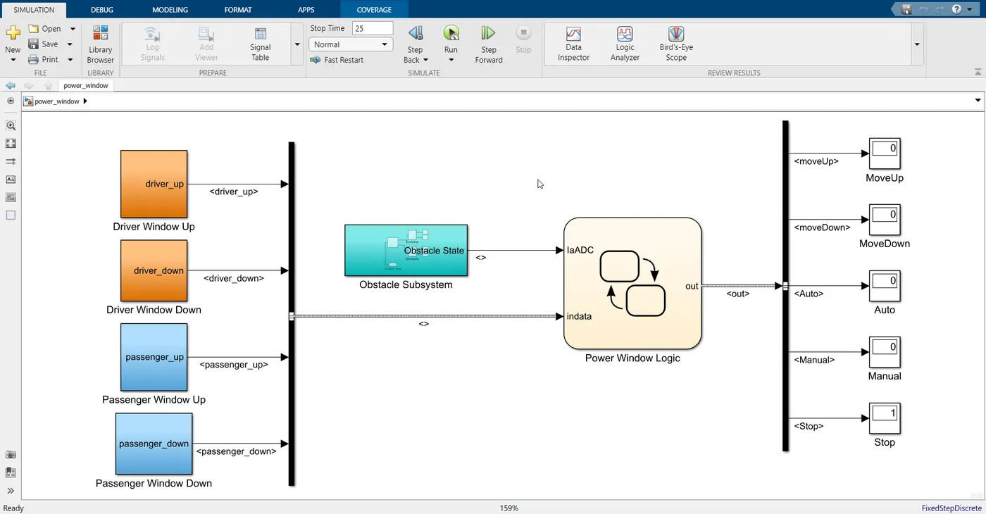
Model Validation:
Model Advisor Report:
The Model Advisor checks your model or subsystem for modeling conditions and configuration settings that cause
inaccurate or inefficient simulation of the system that the model represents. The Model Advisor checks can help you
verify compliance with industry standards and guidelines. By using the Model Advisor, you can implement consistent
modeling guidelines across projects and development teams.
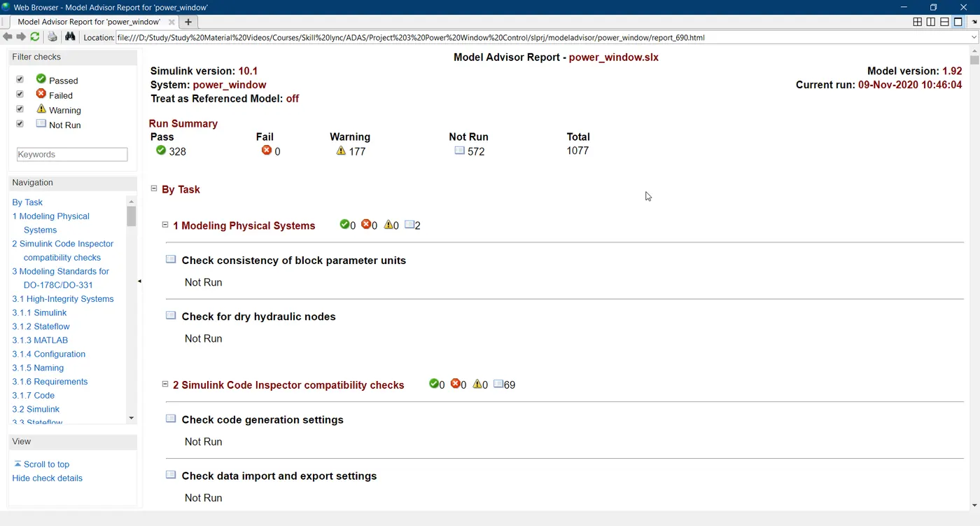
Upon completing the analysis of your model, the Model Advisor produces a report that lists the suboptimal
conditions, settings, and modeling techniques and proposes solutions, when applicable.
Once the signal being specified in SLDD, the next job is to name the important signals in the model. All input and
output signals are given their names specified in SLDD. If signals are originating from a block, then these signals
should be marked as Simulink signal objects. As these signal goes from each subsystem and then blocks, it is
marked as a propagated signal in its further process.
Model Advisor Check: The model Advisor Check option is available in Modelling Tab. As the scope of the project is
small, the Advisor check is carried out for a few parameters only. Warnings got after running the check are resolved
andthe final report is generated and saved. The same report is also attached to the project. It is not necessary to
resolve all the errors, so important errors are resolved which may hamper the code generation process.
Configuration Parameter Update: Once it is sure that the model doesn't have an error, the model set can be set
appropriately. Model Setting option is available under Modelling Tab. All Configuration parameter is set and its
images are saved in ppt. The same ppt is attached to this project.
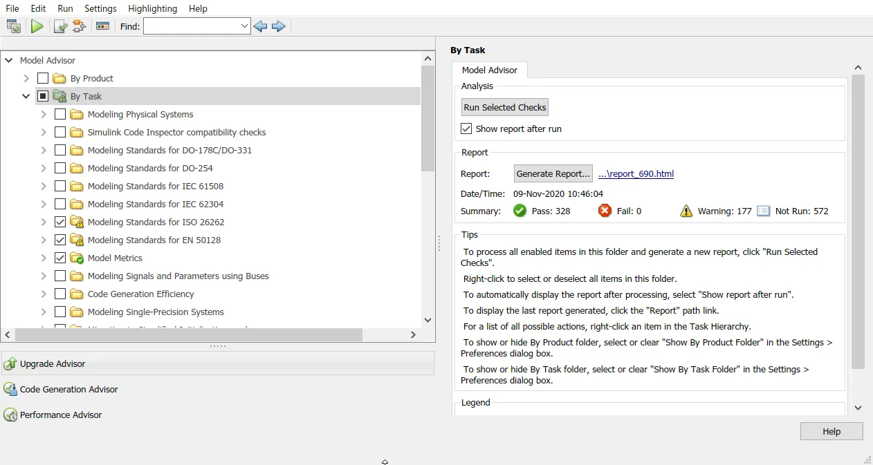
In the model advisor, the model is checked for the following tasks and guidelines,
- Modeling Standards for ISO 26262
- Modeling Standards for EN 50128
- Model Metrics
- Code Generation Efficiency
- Model Referencing
- Modeling Standards for MAB
- Modeling Standards for JMAAB
- Modeling Standards for MISRA C:2012
Model Coverage Analysis:

Code Generation Embedded C:
ert_main.c
power_window.c
Conclusion:
Model File : power_window.slx
Model Advisor Report : Model_Advisor_Report.pdf
C File : power_window.c, ert_main.c