Power Electronics Circuit
AIM
- Why power electronics circuits are efficient? In practice, which types of losses occur in power electronics circuits?
- Using a suitable MATLAB model, show how the duty cycle control signal can be generated for a simple power converter circuit?
- Make a comparison of square wave inverter output voltage with a sine modulated one.
- Explain the difference between VFD and Vector control drive. Can we use the VFD method for the induction motor in EV application?
Solution 1:
Power Electronics :
Power electronics is one of the enabling technologies propelling the shift from conventional gasoline/diesel engine‐powered vehicles to electric, hybrid, and fuel cell vehicles. It mainly involves the use and control of power semiconductor switches, such as power diodes, insulated gate bipolar transistors (IGBTs), and metal oxide field effect transistor.
The power electronics circuit controlled the required amount desired in various vehicles and also convert source to the desired output.
Let for the below example, in series HEV, In this configuration, the internal combustion engine (ICE) drives a three‐phase permanent magnet synchronous generator, whose output is a three‐phase voltage with variable frequency and variable voltage. This output needs to be rectified to DC.
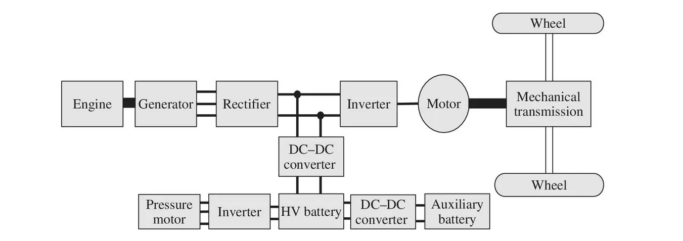
The front wheels are driven by an induction motor that needs to be controlled by a voltage source inverter (VSI) or a current source inverter (CSI). An energy storage system is connected to the DC bus, between the generator/rectifier output and the inverter. However, there is a bidirectional DC-DC converter that manages the charge/discharge of the battery, as well as controlling the DC bus voltage.
In addition, auxiliary components, such as headlights, wipers, entertainment systems, and heat seats, run from the 14 V auxiliary battery. Most advanced hybrid vehicles no longer have an alternator, which means that the 14 V battery needs to be charged from the high‐voltage (HV) battery. On the other hand, even if an alternator is present when the engine is off, the 14 V battery can still be drained quickly without proper charge maintenance. Therefore, it is necessary to have a DC-DC converter to charge the 14 V battery from the HV battery.
Power converters are usually classified by their input and output. Since the input and output of a power converter can be either AC or DC, there can be four types of power converters:
- – DC-DC converter
- – DC–AC inverter
- – AC–DC rectifier
- – AC–AC cycloconverter.
Losses occur in power electronics circuits
- Power Losses :
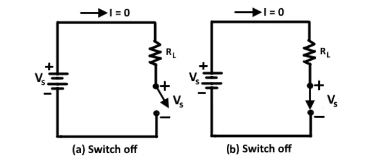
The power losses generated in the switch is the product of the current through the switch and the switch and the voltage across the switch. When the switch is off, there is no current through it. And therefore, there is no power dissipation. When the switch is on, it has current but there is no voltage drop across it, so again there is no power loss.
The ideal switch changes from the off state to on state instantaneously.The power loss during switching is zero.
Conduction Loss :
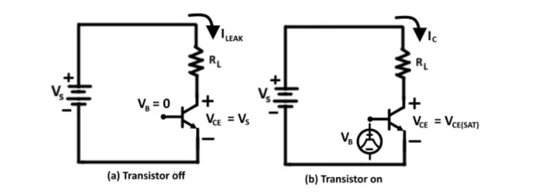
When the transistor is off, it carries a leakage current. However, since the leakage current is quite small and does not vary significantly with voltage, it is usually neglected and thus the transistor power loss is essentially zero.
When the transistor is on, it has a small voltage drop across it. The voltage is called the saturation voltage. The transistor power dissipation or conduction loss due to saturation voltage is :
`P_(ON) = V_(CE(SAT)) *I_C`
Switching Loss :
In addition to conduction loss, a real switch has switching losses because it cannot change from the ON state to the OFF state instantaneously. A real switch takes a finite time to turn ON and a finite time to turn OFF.
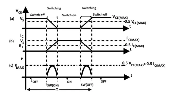
These times not only introduce power dissipation but also limit the highest switching frequency possible. The transition time for switching is generally larger. The figure below shows the switching waveform for (a) voltage source across the switch and current through it. When the switch is OFF the voltage across it is equal to source voltage.
During turn-on, which takes a finite time, the voltage across the switch decrease to zero. During the same time current through the switch increases from zero to I_c. The transistor has current through it and a voltage across it during the switching time, therefore it has zero power loss.
Solution 2:
For our simulation of the duty cycle, we are using a DC-DC converter. A DC-to-DC converter is an electronic circuit or electromechanical device that converts a source of direct current (DC) from one voltage level to another. It is a type of electric power converter. Power levels range from very low (small batteries) to very high (high-voltage power transmission).
Different types of DC-DC converter :
Step-down/Buck Converter :
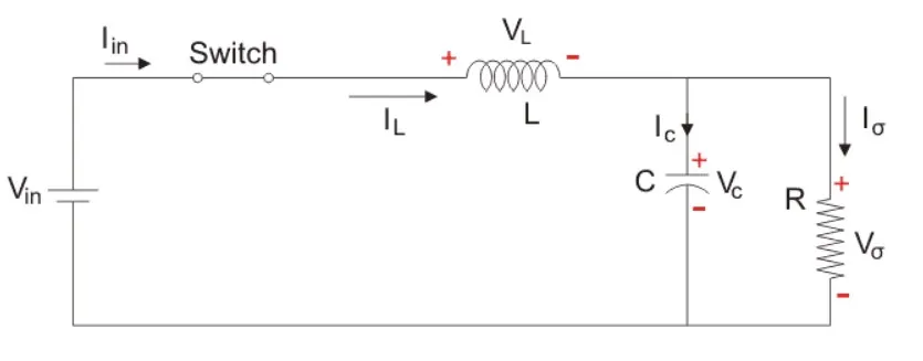
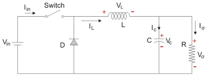
The Step-Down converter or Buck converter reduces the input DC voltage to a specified DC output voltage. Time-based Modulation is mostly used for DC-DC Converter. It is simple to construct and use. The frequency remains constant in this type of PWM modulation.
The Buck converter has two modes of operation. The first mode is when the switch is on and conducting.
MODE 1: Switch ON, Diode is OFF
MODE 2: Switch OFF, Diode is ON
Here, the energy stored in the inductor is released and is ultimately dissipated in the load resistance, and this helps to maintain the flow of current through the load.
Step-Up/Boost Converter :
The Step Up or Boost converter which increases the input DC voltage to a specified DC output voltage across the load.
Time-based Modulation is mostly used for DC-DC Converter. It is simple to construct and use. The frequency remains constant in this type of PWM modulation.
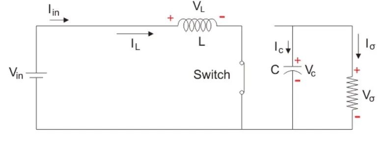
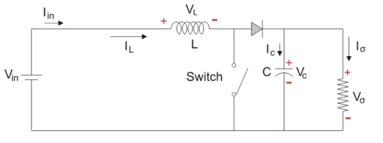
The Boost converter has two modes of operation. The first mode is when the switch is on and conducting.
MODE 1: Switch ON, Diode is OFF
The Switch is ON and therefore represents a short circuit ideally offering zero resistance to the flow of current so when the switch is ON all the current will flow through the switch and back to the DC input source.
MODE 2: Switch OFF, Diode is ON
In this mode, the polarity of the inductor is reversed. The energy stored in the inductor is released and is ultimately dissipated in the load resistance, and this helps to maintain the flow of current in the same direction through the load and also step-up the output voltage as the inductor is now also acting as a source in conjunction with the input source.
Buck-Boost Converter :
The buck-Boost converter can operate as a DC-DC Step-Down converter or a DC-DC Step-Up converter depending upon the duty cycle, D.
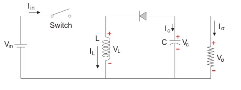
The input voltage source is connected to a solid-state device. The second switch used is a diode. The diode is connected, in reverse to the direction of power flow from the source, to a capacitor and the load, and the two are connected in parallel.
The Buck-Boost converter has two modes of operation. The first mode is when the switch is on and conducting.
MODE 1: Switch ON, Diode is OFF
The Switch is ON and therefore represents a short circuit ideally offering zero resistance to the flow of current so when the switch is ON all the current will flow through the switch and back to the DC input source.
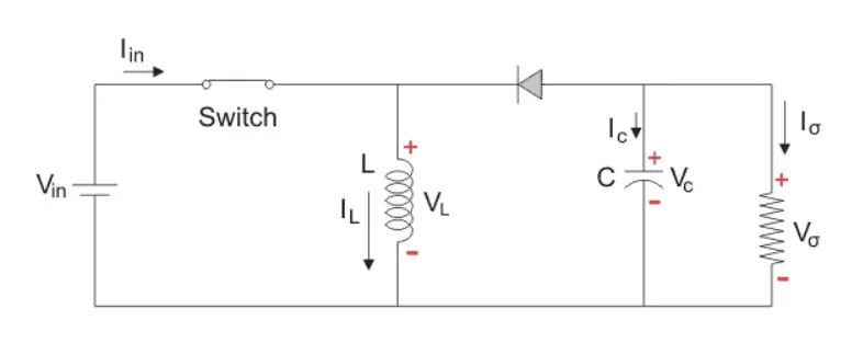
MODE 2: Switch OFF, Diode is ON
In this mode, the polarity of the inductor is reversed. The energy stored in the inductor is released and is ultimately dissipated in the load resistance, and this helps to maintain the flow of current in the same direction through the load and also step-up the output voltage as the inductor is now also acting as a source in conjunction with the input source.
----------------------------------------------------------------------------------------------------------------------------------
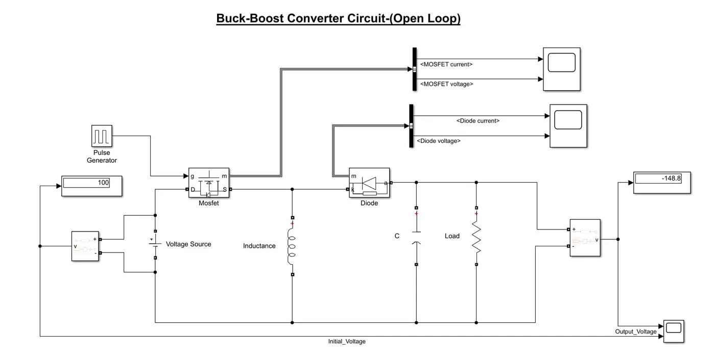
For designing the Simulink model, we have used a buck-boost converter with an open and closed-loop as it provides the advantage of both, and with changing duty cycle we have analyzed its mode of operation.
Buck-Boost Converter(Open Loop):
The Buck-boost converter depends upon the duty cycle of the system provided A duty cycle or power cycle is the fraction of one period in which a signal or system is active.
For our system, if the duty cycle is below 0.5 it operates as Buck operator, and if the duty cycle is greater than 0.5 it operates as a Boost converter.
Buck Mode Operation
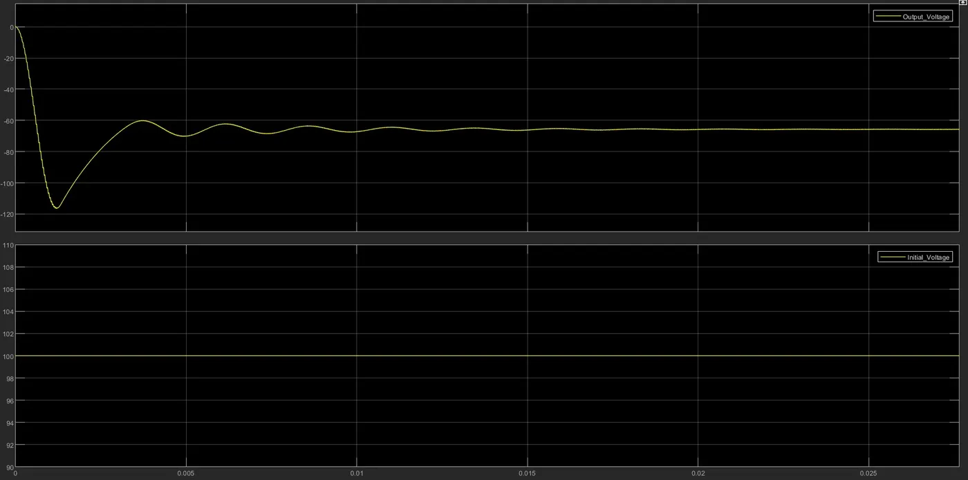
In Buck mode operation we have selected the duty cycle is selected to be 40% which is 0.4.
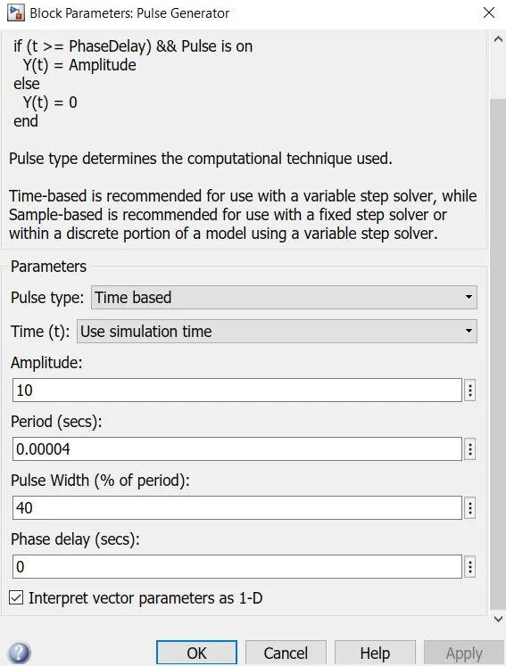
Input Voltage: 100 V
Output Voltage : `= -(D*frac{V_text(in)}{(1-D)})`
`= -(0.4*frac{100}{(1-0.4)}) => -66.66V`
We can see that the output voltage is reduced. This can also be checked by the Simulink model of the system.
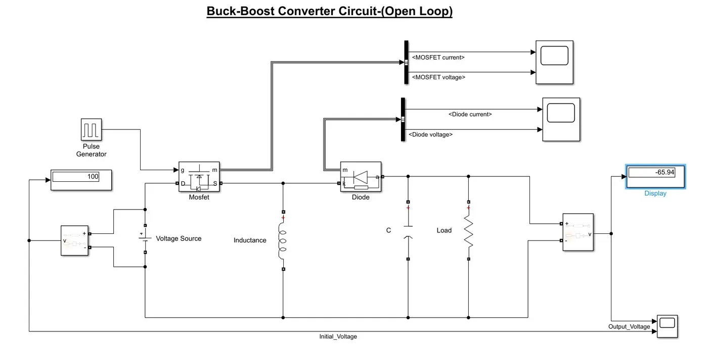
RESULT
Observation
From the above result, we can see that it matches our result, with little error, and the voltage at the output is reduced.
Boost Mode Operation
In Buck mode operation we have selected the duty cycle is selected to be 60% which is 0.6.
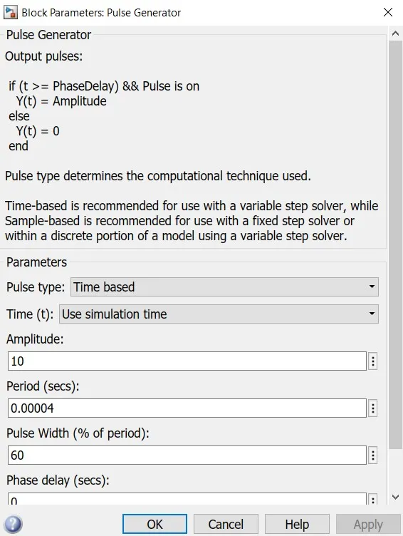
Input Voltage: 100 V
Output Voltage : `= -(D*frac{V_text(in)}{(1-D)})`
`= -(0.6*frac{100}{(1-0.6)}) => -150V`
We can see that the output voltage is reduced. This can also be checked by the Simulink model of the system.
RESULT
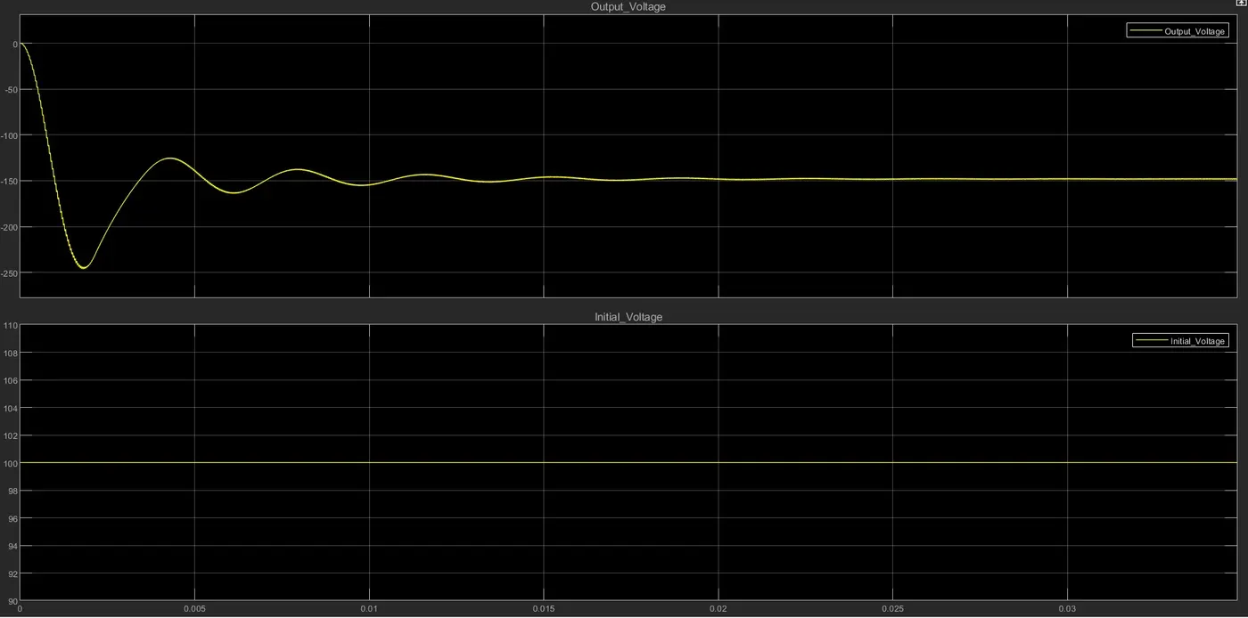
From the above result, we can see that it matches our result, with little error, and the voltage at the output is increased.
Buck-Boost Converter(Closed Loop):
In the close cloop method we use the feedback control method to get the desired output, the desired output can be Buck or Boost mode of operation.
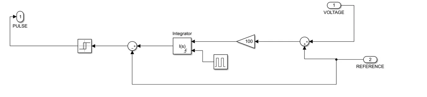
The feedback control mechanism is implemented by the PID controller block.
The below model shows the buck mode of operation.
The desired output is 62 V.
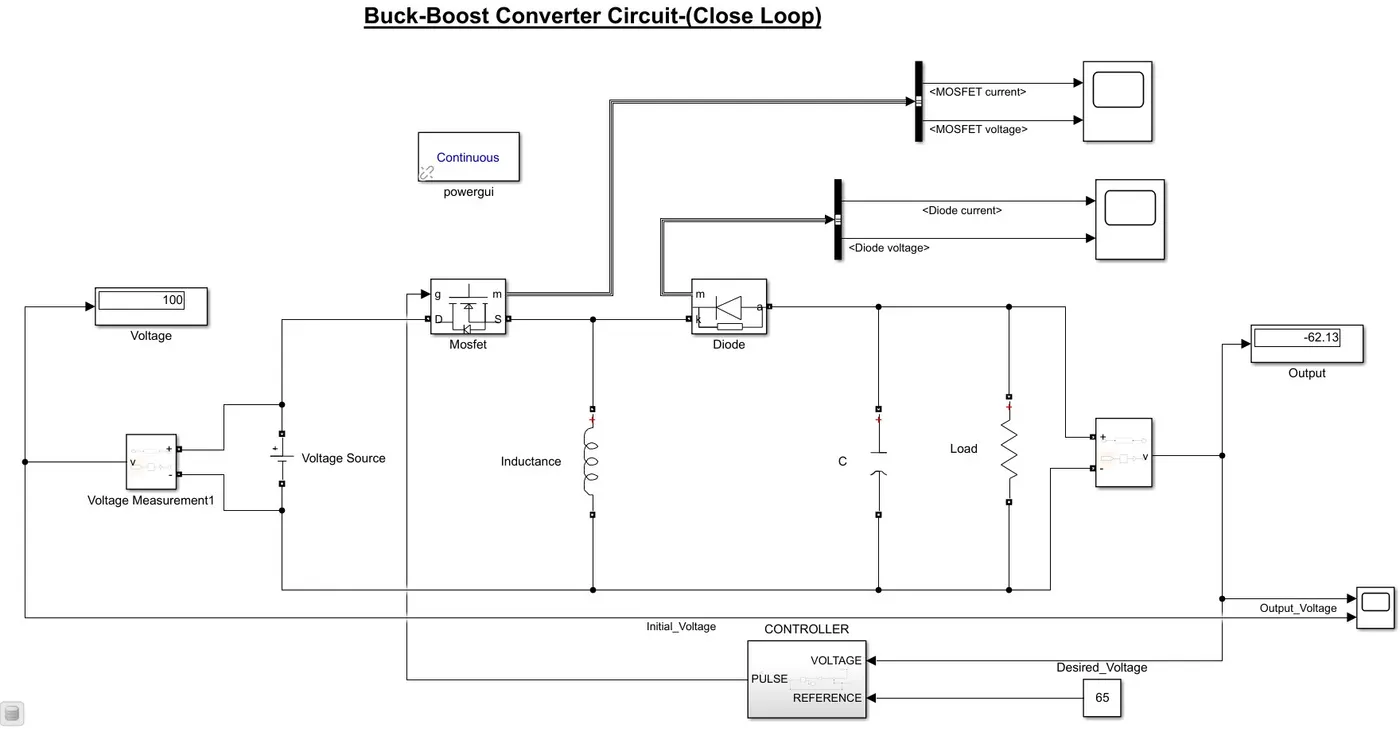
And the controller is given by:
RESULT
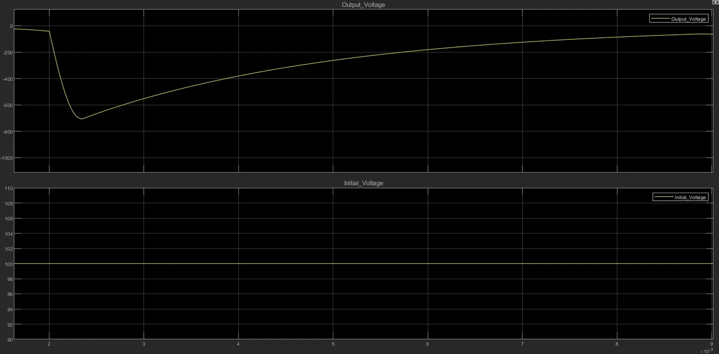
Observation
We can see from the above result that the output is 62.13 V which is in between 5 % of error, which is quite clear from the above graph.
Solution 3:
Sine Modulated Inverter Circuit :
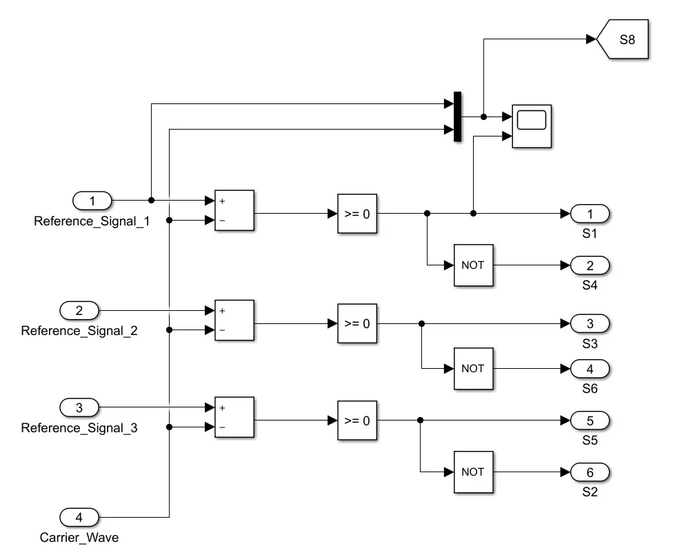
- Sine Modulated inverter circuit consists of a sine wave that is taken as a reference signal at the fundamental frequency. And a sawtooth wave which is a carrier wave at a higher frequency.
- For the output voltage, both signals are compared when Reference Wave > Carrier Wave, the output will be high, which is 1 and when the Reference Wave < Carrier Wave, the output will be low which is 0.
- Sine Modulated Model which is designed in Simulink is shown below.
- Three Phase voltage source is selected for this model with three different phases for the reference signal.
Sine Modulated Inverter model is shown below:
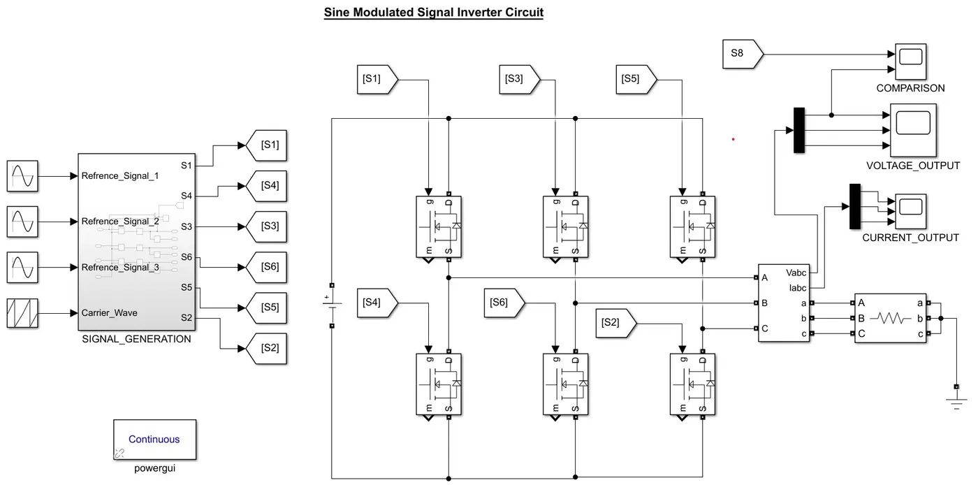
The subsystem for signal generation is given below :
Signal Generated in Our case is shown below:
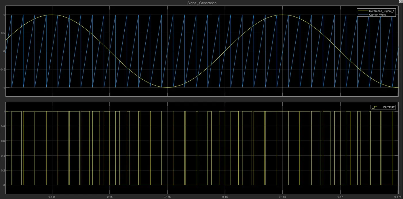
From the above result, we can see that where the reference signal is greater than the carrier signal high signal. is generated and when it is less, a low signal is generated.
The output result, which we get after simulating this example is shown below :
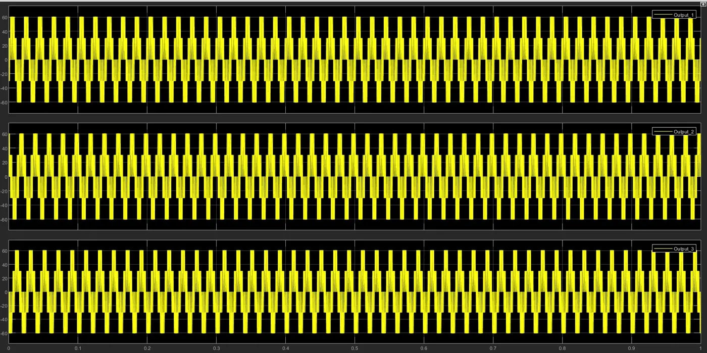
This type of inverter is better than the Square wave inverter and more affordable than the Sine wave inverter. A Modified Sine Converter can be utilized for simple systems, however, there are heaps of equipment that it cannot support.
Square Wave Inverter :
- Square wave inverters are considered to be old tech and are even considered obsolete in some parts of the world. The square wave inverters also convert DC to AC current but they do so by simply flipping the voltage directly from negative to positive and back again.
The square wave inverter model designed in Simulink is shown below :
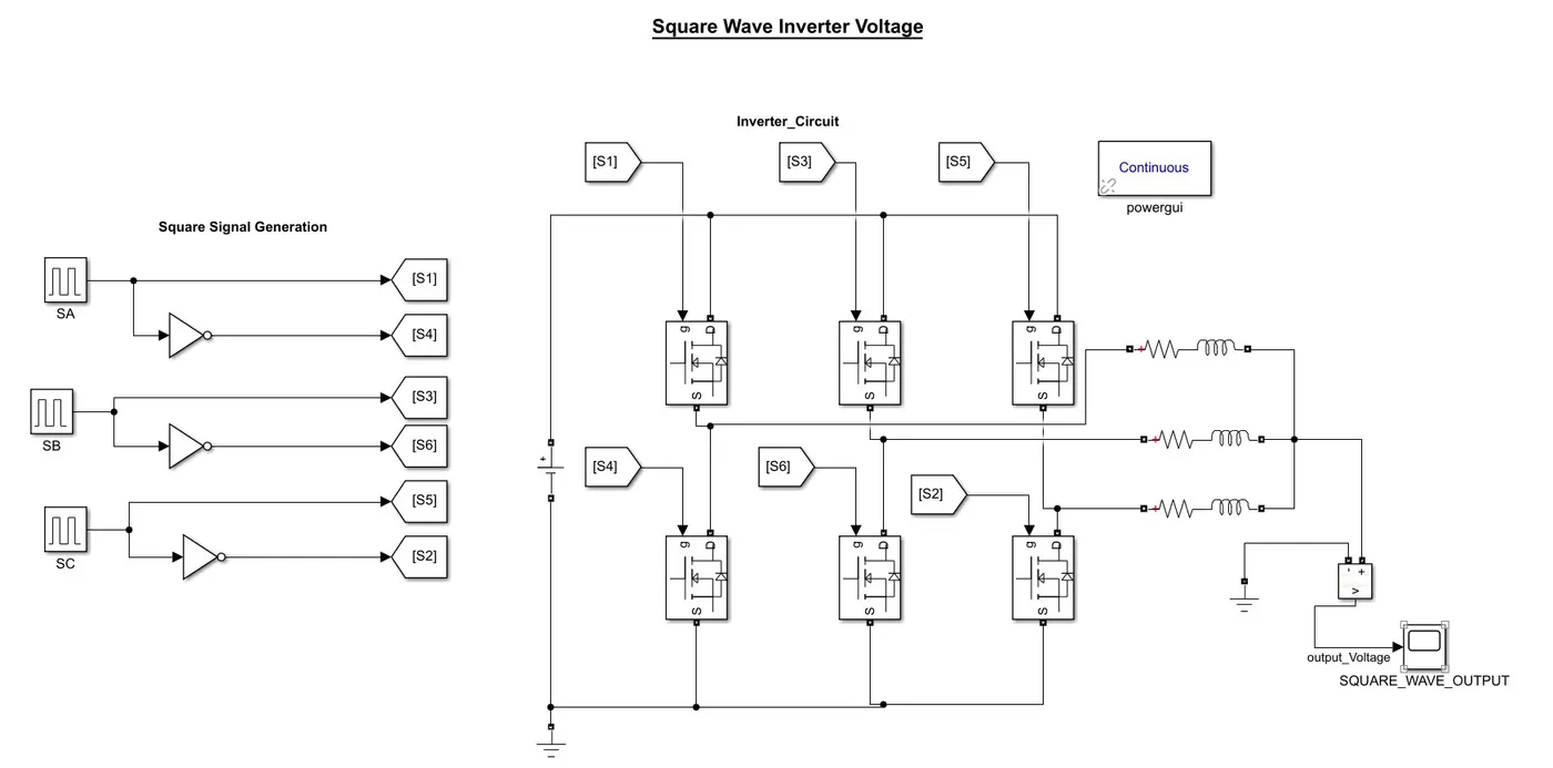
Result obtained after running this simulation is shown below :
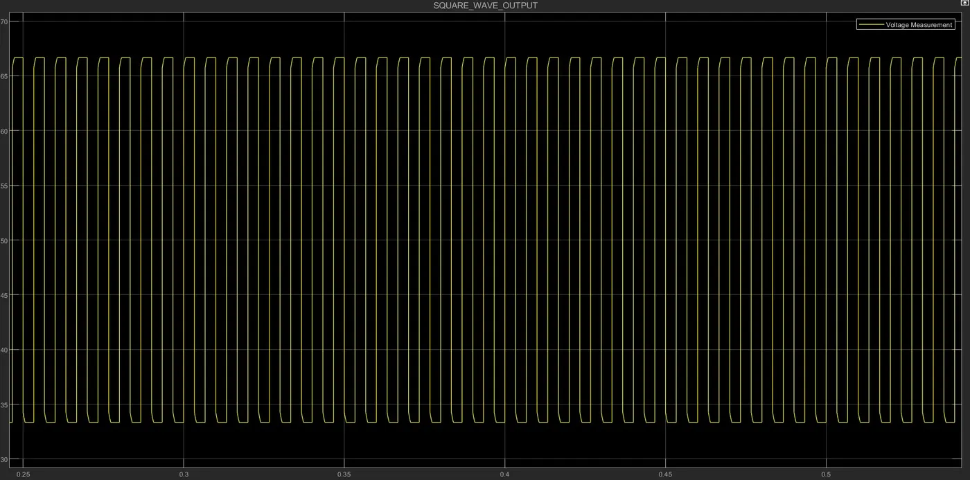 From the above result obtained, we can see that the output is the square wave for the inverter circuit.
Solution 4:
Variable Frequency Drive(VFD) Control Drive :
- A variable frequency drive (VFD) is a type of motor controller that drives an electric motor by varying the frequency and voltage of its power supply. The VFD also has the capacity to control ramp-up and ramp-down of the motor during the start or stop, respectively.
- Even though the drive controls the frequency and voltage of power supplied to the motor, we often refer to this as speed control, since the result is an adjustment of motor speed.
Any Variable Frequency Drive or VFD incorporates the following three stages for controlling a three-phase induction motor:
Rectifier Stage
A full-wave power diode based solid-state rectifier converts three-phase 50 Hz power from a standard 220, 440 or higher utility supply to either fixed or adjustable DC voltage. The system may include transformers for high voltage systems.
Inverter Stage
Power electronic switches such as IGBT, GTO or SCR switch the DC power from the rectifier on and off to produce a current or voltage waveform at the required new frequency. Presently most of the voltage source inverters (VSI) use pulse width modulation (PWM) because the current and voltage waveform at the output in this scheme is approximately a sine wave.
Control System
Its function is to control output voltage i.e. voltage vector of the inverter being fed to the motor and maintain a constant ratio of voltage to frequency (V/Hz). It consists of an electronic circuit that receives feedback information from the driven motor and adjusts the output voltage or frequency to the desired values.
Advantages
Energy Saving
The primary function of VFD in the industry is to provide smooth control along with energy savings. The variable-speed motor drive system is more efficient than all other flow control methods including valves, turbines, hydraulic transmissions, dampers, etc.
Increased Reliability
Adjustable speed motor-drive systems are more reliable than traditional mechanical approaches such as using valves, gears, louvers, or turbines to control speed and flow. Unlike the mechanical control system they don’t have any moving parts hence they are highly reliable.
Vector Control Drive :
- Vector control, also called field-oriented control (FOC), is a variable frequency drive(VFD) control method in which the stator currents of a three-phase AC electric motor are identified as two orthogonal components that can be visualized with a vector.
- One component defines the magnetic flux of the motor, the other the torque. The control system of the drive calculates the corresponding current component references from the flux and torque references given by the drive's speed control.
- A proportional-integral controller(PI) is used to keep the measured current components at their reference values. The pulse width modulation of the variable-frequency drive defines the transistor switching according to the stator voltage references that are the output of the PI current controllers.
- Vector control accordingly generates a three-phase PWM motor voltage output derived from a complex voltage vector to control a complex current vector derived from the motor's three-phase stator current input through projections or rotation back and forth between the three-phase speed and time-dependent system and these vectors' rotating reference-frame two-coordinate time-invariant system.
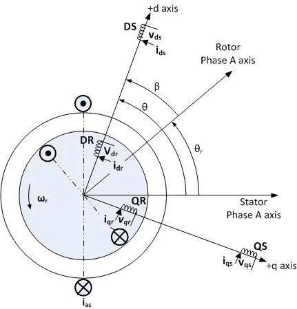
- Such complex stator current space vector can be defined in a (d,q) coordinate system with orthogonal components along with d (direct) and q (quadrature) axes such that the field flux linkage component of current is aligned along the d axis and the torque component of current is aligned along the q axis. The induction motor's (d,q) coordinate system can be superimposed to the motor's instantaneous (a,b,c) three-phase sinusoidal system.
- There are two vector control methods, direct or feedback vector control (DFOC) and indirect or feedforward vector control (IFOC), IFOC being more commonly used because in a closed-loop mode such drives more easily operate throughout the speed range from zero speed to high-speed field-weakening.
- In DFOC, flux magnitude and angle feedback signals are directly calculated using so-called voltage or current models. In IFOC, flux space angle feedforward and flux magnitude signals first measure stator currents and rotor speed for then deriving flux space angle proper by summing the rotor angle corresponding to the rotor speed and the calculated reference value of slip angle corresponding to the slip frequency.
- Yes, we can use the VFD method for the induction motor in EV application, but it reduces the efficiency of the system as it has higher losses associated with it, hence the Vector Control method is preferred.
Conclusion
- A study of the Duty cycle control signal of the simple power converter circuit with the help of Buck-Boost Converter has been done.
- It has been found that, if the duty cycle is less than 0.5 it behaves as a buck converter circuit and if it is greater than 0.5 it behaves as a boost converter circuit.
- Comparison of Sine and modulated signal inverter model has been noted down with the design of both types of models in Simulink.
- The vector Control method performs better than the VFD method, in terms of control for induction motor control in hybrid electric vehicles model, as it has fewer losses associated with it.