Planetary gear mechanism using Solidworks
Motion analysis on the planetary gear Assembly with a carrier.
Animation:-
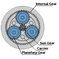
This type of gear assemblies is are mostly used in automatic transmission.
Components - 1 sun gear
4 planetary gears
1 ring gear
1 carrier.
Inputs for design of Gears:-
Ring Gear
- Module = 2.5 (You must use the metric system in design modeler)
- Number of teeth = 46
Sun Gear
- Number of teeth = 14
Input Speed of the Gear = 200 rpm.
Number of planet gears = 4
To calculate the pitch diameter circle and the number of teeth of a planetary gear.
- Diameter of the Planet gear :
Radius of Ring gear= Diameter of the Planet gear + radius of sun gear
Rr = Dp + RsTherfore,
Dp =Rr - Rs
Dp=115/2 - 35/2 = 40mm
D = 40 mm
- Number of teeths of Planet gear:
Pitch diameter, D=m*Twhere m=module
T= Number of teeththerefore,
T=D/m = 40/2.5 = 16
T = 16 teeths
- For creating gear from Toolbox - go to design library - Toolbox - ANSI metric - Power transmission - gears
- For sun and planetary gears choose Spur gear
- For Ring gear to choose Internal Spur Gear
- Pressure angle = 20
- Face Width = 20 mm
Ring gear (Internal spur gear):
Sun gear:
Planet gear:
Carrier model:
Final Assembly:
3D View:
Motion analysis -
before going into cases add contact pairs -
There are total 8 contact pairs -
4 contact pairs - associating with a sun gear and planetary gear (material -apply dry steel)
4 contact pairs - associating with a Ring gear and planetary gear (material -apply dry steel)
There are 3 cases,
Case 1: Ring gear fixed
Motor - sun gear.
Excel datasheet linked here: https://drive.google.com/file/d/1In0t7x0FvJzlY4gPImHY6xRCXfqQenkj/view?usp=sharing
Case 2: Sun gear fixed.
Motor - Ring gear.
Excel datasheet linked here:https://drive.google.com/file/d/1dmRLUMw9r6nlyggeL5ZHl4MgcJBGjI8s/view?usp=sharing
Case 3: Carrier fixed.
Motor - Sun gear.
Excel datasheet linked here: https://drive.google.com/file/d/1L8hMm3no_k3RzFuuDPisv6bo5H59IaEJ/view?usp=sharing
CONCLUSION:
- In the first case, when the input is given to the sun gear and output is obtained at the carrier keeping the ring gear fixed, the planet gear not only rotates about their axis but are also forced to roll on the inside of the ring gear along with the carrier as the Ring gear is fixed. The angular velocity obtained for this case is 279.999deg/sec and varies in a very small fraction.
- In the second case, when the input is given to the ring gear and output is obtained from the carrier keeping the sun gear fixed. The angular velocity achieved is maximum since the internal gear is big and planet gears are small comparatively so when a large gear meshes with a small gear the velocity achieved from the small gear is high because the velocity ratio is high. The angular velocity obtained for this case is 920.00005deg/sec and varies in a very small fraction.
- In the third case, the carrier is fixed and output is to be obtained from the ring gear with the input given to Sun gear, all the gears rotate about their axis. The planet gears rotate only about their axis and transmit motion from sun to the ring and since the ring gear is big in diameter the angular velocity achieved is less. The deviations that are visible in the graphs show that there are points where sliding is occurring between the gears. For making the graph more smoother we can use precise contact. The angular velocity obtained for this case is around 365.217 deg/sec and varies in a very small fraction.