Planetary Gear
AIM :
- To design and model the 3D models of the Ring gear,Planet gear, Sun gear using the inputs provided. Ring Gear Module = 2.5 Number of teeth = 46 Sun Gear Number of teeth = 14 Input Speed of the Gear = 200 rpm. Number of planet gears = 4
- To perform motion analysis and simulation on the following cases,
Sl.No Input Output Fixed 1 Sun Gear Carrier Ring Gear 2 Ring Gear Carrier Sun Gear 3 Sun Gear Ring Gear Carrier
- To plot the angular velocity of the output part as a graph for the above mentioned conditions.
- To discuss the above mentioned plots and results in detailed manner.
Planetary Gearing :
1.What it is ? : Also known as Epicyclic gearing.It is a gear system consisting of one or more outer, or planet, gears or pinions, revolving about a central sun gear or sun wheel. Typically, the planet gears are mounted on a movable arm or carrier, which itself may rotate relative to the sun gear.
2.Why it is used ? :Planetary gears are used as speed reducers. They are used to slow down motors and increase the torque. Torque is the working power of the machine.Planetary gears are often used when space and weight are an issue, but a large amount of speed reduction and torque are needed. This requirement applies to a variety of industries, including tractors and construction equipment where a large amount of torque is needed to drive the wheels.
3.Advantages : Increased repeatability,Perfect precision,Lower noise level because there is more surface contact,Greater durability,Maximum versatility,Increased torque transmission,Very good levels of efficiency.
4.Applications : Industrial automation machines, vending machines or robotics,automatic transmissions of the vehicle.
Working mechanism :
An epicyclic gear train (also known as a planetary gearset) consists of two gears mounted so that the center of one gear revolves around the center of the other. A carrier connects the centers of the two gears and rotates to carry one gear, called the planet gear or planet pinion, around the other, called the sun gear or sun wheel. The planet and sun gears mesh so that their pitch circles roll without slip. A point on the pitch circle of the planet gear traces an epicycloid curve. In this simplified case, the sun gear is fixed and the planetary gear(s) roll around the sun gear.
An epicyclic gear train can be assembled so the planet gear rolls on the inside of the pitch circle of a fixed, outer gear ring, or ring gear, sometimes called an annular gear. In this case, the curve traced by a point on the pitch circle of the planet is a hypocycloid.
The combination of epicycle gear trains with a planet engaging both a sun gear and a ring gear is called a planetary gear train.
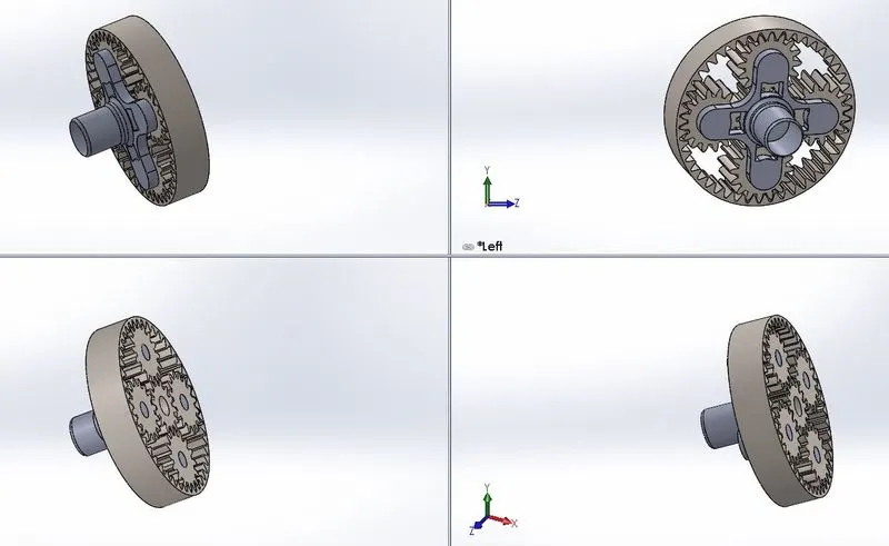
1.Sun: The central gear. It has a larger size and rotates on the central axis. 2.The planet carrier: Its objective is to hold up to 3 gears of the same size, which mesh with the sun gear. 3.Crown or ring: an outer ring (with teeth on its inner side) meshes with the satellites and contains the whole epicyclical train. In addition, the core can also become a center of rotation for the outer ring, allowing it to easily change directions.
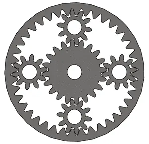
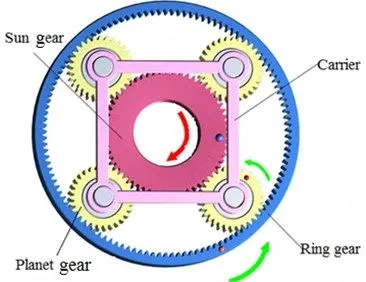 MECHANISM Components Layout
METHODOLOGY:
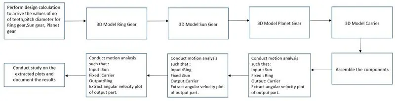
3D Modelling :
Design calculation of gears :
Sun Gear :
Input : Module,m = 2.5 No of teeth,z = 14
Pitch Diameter,Ds = m*z
Pitch Diameter,Ds=2.5*14 = 35
Ring Gear :
Input : Module,m = 2.5 No of teeth,z = 46
Pitch Diameter,Dr = m*z
Pitch Diameter,Dr =2.5*46 = 115
Planet Gear :
Input : Module,m = 2.5
Pitch Diameter,Dp = Pitch Radius of ring gear - Pitch Radius of sun gear
= (Dr/2)-(Ds/s)
= (115/2)-(35/2)
Pitch Diameter,Dp = 40
No of teeth, z = Pitch Diameter / module
=40/2.5
No of teeth, z = 16
| Gear | Pitch Diameter(in mm) | No of teeth | Module |
| Sun | 35 | 14 | 2.5 |
| Planet | 40 | 16 | 2.5 |
| Ring | 115 | 46 | 2.5 |
The gears can be directly imported from the design library of the Solidworks package.
To import gears from Assembly follow the steps given below :
Design Library > Toolbox > ANSI Metric > Power Transmission > Gears
From Gears select Internal Spur gear for Ring gear and Spur gear for Sun and planetary gears.
Select Pressure angle = 20 .
Face width = 20.
RING GEAR :
Inputs given :
Diametral Pitch = 0.5 ( 1 /m = 0.4 but in solidworks available value is 0.5 which is nearest to our 0.4 so select 0.5 as diametral pitch)
No of teeth : 46
Face width : 20
Pressure Angle : 20
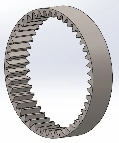
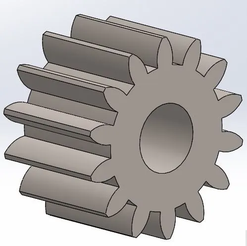
Sun Gear :
Inputs given :
Diametral Pitch = 0.5 ( 1 /m = 0.4 but in solidworks available value is 0.5 which is nearest to our 0.4 so select 0.5 as diametral pitch)
No of teeth : 14
Face width : 20
Pressure Angle : 20
Nominal Shaft Diameter : 11
Planet Gear :
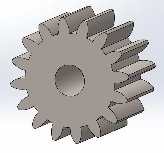
Inputs given :
Diametral Pitch = 0.5 ( 1 /m = 0.4 but in solidworks available value is 0.5 which is nearest to our 0.4 so select 0.5 as diametral pitch)
No of teeth : 16
Face width : 20
Pressure Angle : 20
Nominal Shaft Diameter : 9
Carrier :
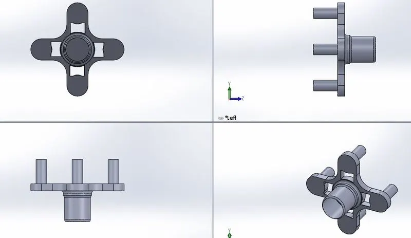
Boss Extrude,Sketch,fillet are the features used.
Planetary Gear Assembly :
Motion Analysis :
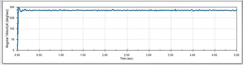
ANALYSIS 1 :
| Sl.No | Input | Output | Fixed |
| 1 | Sun Gear | Carrier | Ring Gear |
Motor is coupled to the sun gear , RPM input : 200 rpm
Ring gear is fixed
Plot of angular velocity of the carrier :
ANALYSIS 2 :
| Sl.No | Input | Output | Fixed |
| 2 | Ring Gear | Carrier | Sun Gear |
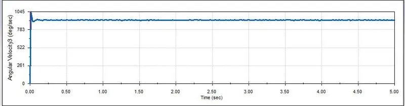
Motor is coupled to the Ring gear , RPM input : 200 rpm
Sun gear is fixed
Plot of angular velocity of the carrier
ANALYSIS 3 :
| Sl.No | Input | Output | Fixed |
| 3 | Sun Gear | Ring Gear | Carrier |
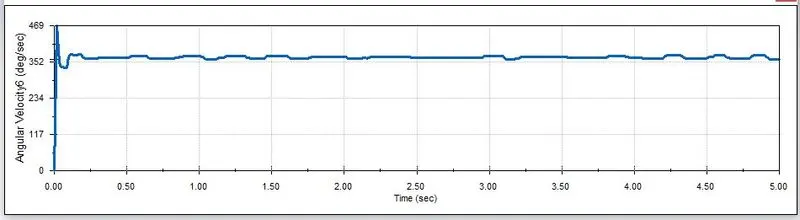
Motor is coupled to the Sun gear , RPM input : 200 rpm
Carrier is fixed
Plot of angular velocity of the Ring gear.
ANIMATIONS :
https://drive.google.com/drive/folders/182OaWuHUKOJBM9Y_ywD9sfiqkfCPgZI8
OBSERVATION :
The angular velocity is achieved maximum (1045 deg/sec) at the case 2 where Sun gear is fixed and the input is given to Ring gear(more number of teeth) which transmits the motion to carrier through planet gear which has less number of teeth,when a gear with more teeth meshes with gear with less teeth ,the angular velocity achieved will be more as the gear ratio is less. Gear ratio is inversely proportional to angular velocity of output gear.In other two cases , the angular velocity achieved is less compared to case 3 condition since they were meshed in such a way smaller gear drives the larger one .