Planetary Gear
Aim: MODELLING AND SIMULATION OF PLANETARY GEAR SYSTEM IN SOLIDWORKS AND DO MOTION STUDY TO FIND ANGULAR VELOCITY AT DIFFERENT CONDITION.
Introduction:
What is a Planetary Gear System?
: Epicyclic gearing or planetary gearing is a gear system consisting of one or more outer, or planet, gears or pinions, revolving about a central sun gear or sun wheel. Typically, the planet gears are mounted on a movable arm or carrier, which itself may rotate relative to the sun gear.
Application:
This type of gearing is sometimes used in tractors and construction equipment to provide high torque to the drive wheels. In bicycle hub gears, the sun is usually stationary, being keyed to the axle or even machined directly onto it. The planetary gear carrier is used as input.
Design:
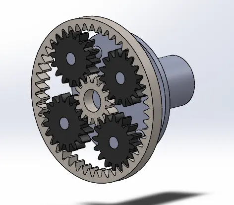
Fig: Assembly
Solidworks Part Design Procedure:
Parts Design:
Since we are using the design toolbox (Metric) for gears, we do not need to design the gears. However, we need to have the module, the number of teeth on the gears.
With the help of module and number of gear, we can find the pitch circle diameter and the gear ratio for gear meshing.
Given,
Module = 2.5 (You must use the metric system in design modeler) same for all the gears
Ring Gear (Internal Spur Gear)
Number of teeth = 46
Pitch Circle = 462.5 = 115mm
Sun Gear (Spur Gear)
Number of teeth = 14
Pitch Circle = 142.5 = 35mm
Shaft = 18mm
Planet Gears (Spur gear)
Input Speed of the Gear = 200 rpm.
Number of planet gears = 4
Pitch Circle = 162.5 = 40mm
Shaft = 10mm
Carrier
Diameter = 115mm
Shaft = 10mm
Part 1- Ring Gear:
Open the SolidWorks, select a new file and select Assembly, (Do select the unit system as mm/metric), once you are in part; go to sketch and select the Right plan.
Now, select the circle and draw three circles of radius 115mm (from plane center), 40mm and 35mm (From Plane center).
Now, define the sketch by making a 40mm circle tangent with a 35 mm circle and making it horizontal as well. After going to circular pattern and select 40mm circle and make it pattern along the same center as shown in below fig and after this exit, the sketch and this sketch is for the mate arrangements of gears to have the rotation around.
Now go to design Library and select ANSI Metric toolbox, then go to powertrain and select gear,
Now select the internal spur gear and give it the count of teeth (46) and other dimensions as per preference.
Part 2- Sun Gear
Go to Design Library and select ANSI Metric toolbox, then go to powertrain and select gear,
Now select the spur gear and give it the count of teeth (14) and other dimensions as per preference.
Part 3- Planet gears
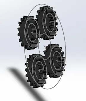
Go to Design Library and select ANSI Metric toolbox, then go to powertrain and select gear,
Now select the spur gear and give it the count of teeth (16) and other dimensions as per preference.
Get the one copy of the gear and once it is inside the plane, use the control key and drag as three copies of the same.
Part 4- Carrier
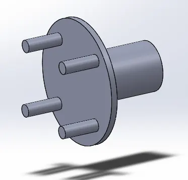
You can do this inside the assembly or outside the assembly by creating an additional part, I did inside the assembly.
Assembly:
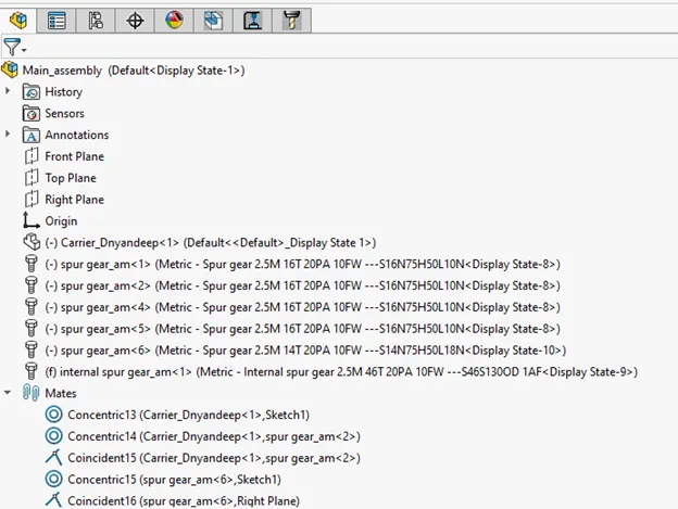
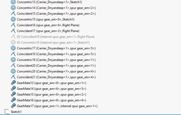
Now I have used the following mates for each part,
Motion Study:
Now go to SOLIDWORKS ADD ONs and select SOLIDWORKS MOTION
Now select the MOTION ANALYSIS for the motion study.
Input Speed of the Gear = 200 rpm.
1 Task:
Input: Sun Gear Output: Carrier Fixed: Ring Gear
For motion study, I contacted two parts the carrier shaft and one planet gear. Apart from this, I have given the rotation (motor) to sun gear shaft face i.e. of 200RPM. And the plot shows the below details.
Plot:
The plot is plotted with Angular Velocity (deg/s) against time as shown below. For plot, I used the carrier outer shaft face as it is the output in this case.
As we can see in the plot, the velocity, in the beginning, was very steady from a second and that is because of the initial contact of the sun gear with planet gear but here forth we can see the angular velocity fluctuated a lot and that is because of the contact and losses between the transmissions of motion. But if we have to get the mean of the speed as for design perspective, we can take the average speed.
- Task:
Input: Ring Gear Output: Carrier Fixed: Sun Gear
For motion study, I contacted two parts the carrier shaft and ring gear. Apart from this, I have given the rotation (motor) to ring gear i.e. of 200RPM. And the plot shows the below details.
Plot:
The plot is plotted with Angular Velocity (deg/s) against time as shown below. For plot, I used the carrier outer shaft face as it is the output in this case.
As we can see in the plot, this shows something different from the earlier study as the angular velocity started fluctuation from the beginning and that is because of the part which is fixed now, but we can see the angular velocity fluctuated a lot and that is because of the contact and losses between the transmissions of motion. However, the speed is more as compared to an earlier study, where we fixed the ring gear and gave motion to the sun gear. I see, this is because of the gear ratio between the planet gear and ring gear, which increases the rotation.
- Task:
Input: Sun Gear Output: Ring Gear Fixed: Carrier
For motion study, I contacted two parts the sun gear and planet gear. Apart from this, I have given the rotation (motor) to sun gear shaft face i.e. of 200RPM. And the plot shows the below details.
Plot:
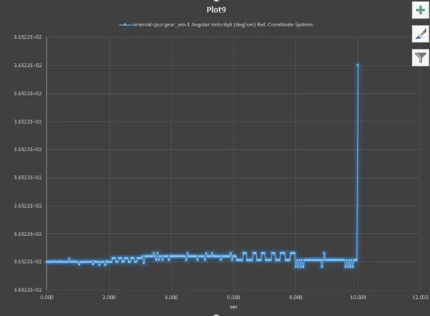
The plot is plotted with Angular Velocity (deg/s) against time as shown below. For plot, I used the carrier outer shaft face as it is the output in this case.
As we can see in the plot, this shows something different from the earlier study as the angular velocity is almost steady through the motion time and that is because of the part which is fixed now, but we can see the angular velocity fluctuated a lot in pattern and that might be because of the forces which may arise at a particular speed or the meshing of the gears and which causes the losses between the transmissions of motion. However, the speed is more as compared to Task 1 and less than Task 2 study, but the velocity is more stable during this study. I see this is because of the gear meshing and all the gears are free to move.
Result and Explanation:
I have examined and observed the differences in three motion studies which I did as part of the assignment, and I could see the very obvious difference is the speed (Angular Velocity). It is very obvious due to the different contact and input motion to different parts.
Task 1, where the ring gear is fixed has the slowest speed among three tasks and that too with quite a lot of disturbance. Whereas Task 2, in which the sun is fixed and the input is ring gear as shown the highest speed among three tasks, yes and this has quite a lot disturbance. Task 3, has shown some quite good results as it is the steadiest among three and has more speed than Task 1.
Moreover, what I can deduct from the above studies is that the motion when it is transferred from gear to gear, will certainly have the fluctuation/disturbance (losses) but when it meshed correctly and the input is given to the correct part then it will certainly give the steady output.
Part drive link:
https://drive.google.com/drive/folders/1kC3KXZ9Z5LN3SDAhf1kx8I4ReksosXKw?usp=sharing
Errors or issues I faced:
The biggest issue I faced was, how to mate the carrier to the gears, as I was following the process taught in the video. But I couldn’t make the mate correctly. It took me 5 days to understand the correct way of doing it. In the end, it was just a simple change but I know I took very long to understand it but in the process, I could explore more. (Earlier I was mating the gears as concentric to the sketch circles, but later I realize if I do that I will not be able to make the carrier shaft concentric with gear as for rotation motion. Then After 5 days of thinking I myself realized that I am over defining the mating and then I simply did the gear mating on the carrier shaft)
Reference: