PIPE FLOW SIMULATION
OBJECTIVE
Run a pipe flow simulation with an inlet Reynolds number of 100,1000 and 10,000.
For each of these cases do the following
1. Place line probes at 95%, 90% and 85% of the pipe length.
2. Compare the normalized velocity profile at each of these locations
3. Normalize the velocity profile by the inlet velocity.
THEAORY
Reynolds Numbers
Fluid flow in a pipe encounters frictional resistance due to the internal roughness (e) of the pipe wall, which can create local eddy currents within the fluid. Calculation of the Reynolds Number helps to determine if the flow in the pipe is Laminar Flow or Turbulent Flow.
Reynolds Number Calculation
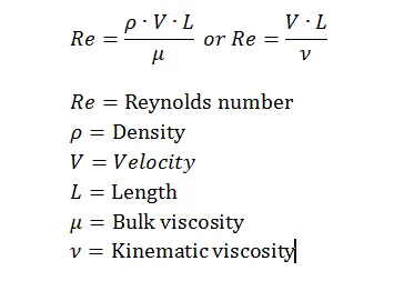
The Reynolds number (Re) of a flowing fluid is calculated by multiplying the fluid velocity by the internal pipe diameter (to obtain the inertia force of the fluid) and then dividing the result by the kinematic viscosity (viscous force per unit length).
Kinematic viscosity = dynamic viscosity/fluid density
Reynolds number = (Fluid velocity x Internal pipe diameter) / Kinematic viscosity
Laminar Flow in a Pipe
Laminar flow occurs when the calculated Reynolds number is less than 2300 and in this case the resistance to flow is independent of the pipe wall roughness.
Turbulent Flow in a Pipe
Turbulent flow occurs when the Reynolds number calculation exceeds 4000.
At 20 degree celcius, the Dynamic Viscosity is 0.001002 (N s/m2)
INPUTS:
Diameter of pipe: 0.02m
Length of the pipe: 1m
Dynamic viscosity of water= 0.001002
Reynolds number = (rho x Velocity x D)/Dy.visosity.
by applying the above inputs and formula for Reynolds number,(Re=100,1000 & 10000)
clear all
close all
clc

%inputs
renoylds_number = [ 100 1000 10000]
dynamic_viscosity = 0.001002
fluid_density  = 1000
diameter = 0.02

%Velocity calculation usinng renoylds number
velocity = (renoylds_number*dynamic_viscosity)/ (fluid_density*diameter)
We get,
velocity =

   0.0050100   0.0501000   0.5010000
PROCEDURE:
- First create a sketch of diameter 0.02m and then click on extrude give a length of 1m.
- After that click on shell command and select both the faces of model and then enter the thickness of 1mm.
- Create new sketch along length of the pipe, make line probe in 85%, 90% and 95% of length of the pipe.
- Then go to flow simulation and select create lid for both sides of pipe and make cylindrical pipe as closed volume.
- Click new project in flow simulation toolbar.
- Fluid taken for this project is water, flow type laminar and turbulent, initial conditions for pressure 101325 Pa, temperature 293.2K and velocity is 0m/s.
- Boundary conditions are,
- Static pressure at outlet 101325 Pa,
- Initial velocity is 0.005 m/s (Re100), will change according to Re 1000 & Re10000.
- Real wall for surface of pipe.
- Creating XY plot for 85% probe and create another XY plot to compare all the three probes.
- Create global mesh manually as X=20, Y=20 and Z=100.
- Click new parametric study and make input & output variables.
- Run.
RESULTS
Velocity cut at 0.005 m/s
Velocity cut at 0.05 m/s
Velocity cut at 0.5 m/s
Velocity at the line probe 85 %
Velocity at the line probe 90%
Velocity at the line probe 95%
Comparison of velocities
CONCLUSIONS
- Reynolds number is changing because of this, the velocity is also changing. So that the flow is changing from laminar to the turbulent.
REFFERENCES