Photo Realistic Rendering
DESIGNING, ASSEMBLYAND REALISTIC RENDERING
OF AN AMERICAN CHOPPER
<!-- [if !supportLists]--> Ø <!--[endif]-->To create Photo Realistic Views of Chopper Bike with a custom 3D model American chopper. To learn SolidWorks user interface for sketching and modeling of various external parts of chopper under a part modeling environment with suitable sketches, commands and constraints are used in SolidWorks 2021 or Photo view 360.
<!-- [if !supportLists]--> Ø To become proficient in SolidWorks by working on various parts of chopper assembled and adding rendering effect to each part of chopper become more realistic nature.
<!-- [if !supportLists]--> Ø <!--[endif]-->To be ready for industry as a Mechanical Design Engineer.
INTRODUCTION:
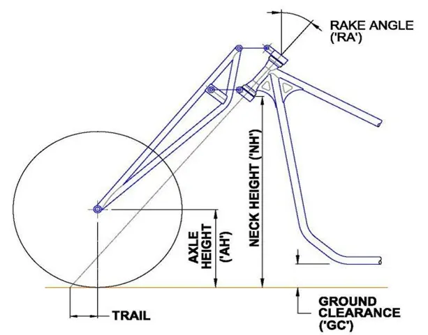
A chopper is one of the types of Custom motorcycle which employs radically modified steering angles and lengthened forks for a stretched-out appearance. Rake angle has a crucial role in motorcycle’s handling characteristics. If the rake angle or castor angle is high, it leads to better straight-line stability, but cornering capability is reduced. Lower the castor angle leads to excellent cornering but reduced straight line stability.
They can be built from an original motorcycle which is modified ("chopped") or built from scratch.
 DESIGN METHODOLOGY
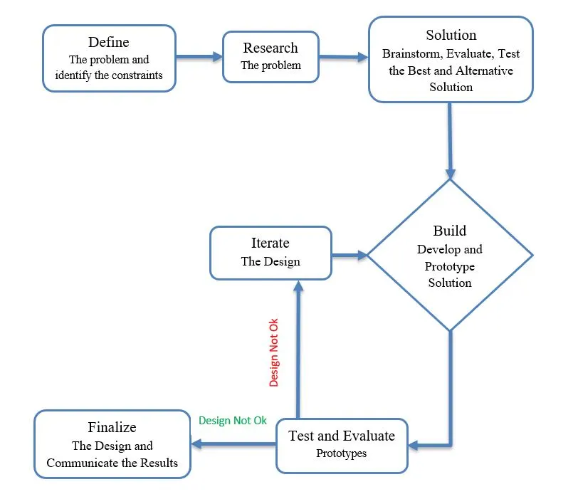
<!-- [if !supportLists]-->Ø <!--[endif]-->It is the Research and development of innovative design processes and techniques used to improve the quality and functionality of new and existing products. In one word design is from scratch or sketching to final design product.
<!-- [if !mso]-->
<!--[endif]-->Design methodology is determined by several steps explained in flow chart.
INTRODUCTION TO SOLIDWORKS
Solid works is a 3D modeling Computer-Aided Design and Computer-Aided Engineering applications Published by Dassault Systems. Three templates are used for creating 3D models, assembly and converting into detailed drawing.
They are 1) Part Modeling 2) Assembly 3) Drawing
PART MODELING
Modeling in general means creating a virtual prototype of an object. First open the solid works tool and select the part template. We are getting into part modeling user interface and select plane which we are going to Building a model in SolidWorks usually starts with a 2D sketch (although 3D sketches are available for power users). The sketch consists of geometry such as points, lines, arcs, conics (except the hyperbola), and splines. Dimensions are added to the sketch to define the size and location of the geometry. Relations are used to define attributes such as tangency, parallelism, perpendicularity, and concentricity. The parametric nature of SolidWorks means that the dimensions and relations drive the geometry, not the other way around. The dimensions in the sketch can be controlled independently, or by relationships to other parameters inside or outside the sketch.
ASSEMBLY
Mates are plays key role for assembly, just as sketch relations define conditions such as tangency, parallelism, and concentricity with respect to sketch geometry, assembly mates define equivalent relations with respect to the individual parts or components, allowing the easy construction of assemblies. SolidWorks also includes additional advanced mating features such as gear and cam follower mates, which allow modeled gear assemblies to accurately reproduce the rotational movement of an actual gear train. There are two types of assemblies in cad software. They are 1) Bottom-Up Design 2) Top-Down Design
<!-- [if !supportLists]-->1) <!--[endif]-->Bottom-Up Design
It is a design methodology in which all parts are designed independently without any reference in assembly. In this project all parts are modelled individually and assembled together by Bottom-up approach.
<!-- [if !supportLists]-->2) <!--[endif]-->Top-Down Design
Sub parts are created with the help of the main concept called reference Sketch. Initial part or fixed part used to develop the small parts or components.
In this Project All parts of American chopper are designed independently and assembled by using Bottom-Up Assembly.
APPLICATIONS OF SOLIDWORKS
<!-- [if !supportLists]-->Ø <!--[endif]-->Aero Space
<!-- [if !supportLists]-->Ø <!--[endif]-->Defense
<!-- [if !supportLists]-->Ø <!--[endif]-->Automotive
<!-- [if !supportLists]-->Ø <!--[endif]-->Electrical Panels
<!-- [if !supportLists]-->Ø <!--[endif]-->Electro-Mechanical Equipment’s
<!-- [if !supportLists]-->Ø <!--[endif]-->Machinery
<!-- [if !supportLists]-->Ø <!--[endif]-->Medical Use
<!-- [if !supportLists]-->Ø <!--[endif]-->Mining and Drilling Machine
<!-- [if !supportLists]-->Ø <!--[endif]-->Heavy Equipment etc.
COMPONENTS OF CHOPPER
<!-- [if !supportLists]-->1. <!--[endif]-->Transmission Belt
<!-- [if !supportLists]-->2. <!--[endif]-->Kickstand
<!-- [if !supportLists]-->3. <!--[endif]-->Front Fender
<!-- [if !supportLists]-->4. <!--[endif]-->Rear Fender
<!-- [if !supportLists]-->5. <!--[endif]-->Oil Tank
<!-- [if !supportLists]-->6. <!--[endif]-->Chain
<!-- [if !supportLists]-->7. <!--[endif]-->Pedal
<!-- [if !supportLists]-->8. <!--[endif]-->Front Wheel
<!-- [if !supportLists]-->9. <!--[endif]-->Rear Wheel
<!-- [if !supportLists]-->10. <!--[endif]-->Front Fork
<!-- [if !supportLists]-->11. <!--[endif]-->Chassis
<!-- [if !supportLists]-->12. <!--[endif]-->Engine
<!-- [if !supportLists]-->13. <!--[endif]-->Gas Tank
<!-- [if !supportLists]-->1. <!--[endif]-->TRANSMISSION BELT
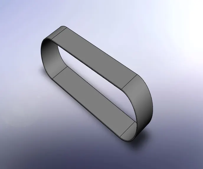
In belt Friction-locked, i.e., power is transmitted through frictional forces between pulley and belt and vice versa.Flat belt drives, power transmission is generally or V- belts are very often used. An exception to friction-locking power transmission are toothed belts (timing belts), in which the power transmission is carried out positively by teeth attached to the belt, which engage in the puley. Power transmission between at least two pulleys by a belt. One pulley drives the belt (driving pulley) and the other pulley is driven by the belt (driven pulley). In belt drives, the speed is often reduced, so that in these cases the smaller of the two pulleys is the driving pulley. Belt drives are the cheapest utility for power transmission systems. A belt drive bike uses a continuous toothed belt made from resilient synthetic materials such as nylon and carbon fibre.
COMMANDS: To create the Transmission belt the following Features are used.
<!-- [if !supportLists]-->· <!--[endif]-->Plane
<!-- [if !supportLists]-->· <!--[endif]-->Sketch (Line)
<!-- [if !supportLists]-->· <!--[endif]-->Constraints
<!-- [if !supportLists]-->· <!--[endif]-->Smart Dimensions
<!-- [if !supportLists]-->· <!--[endif]-->Extrude Boss/Base
<!-- [if !supportLists]-->· <!--[endif]-->Offset
<!-- [if !supportLists]-->· <!--[endif]-->Fillet
<!-- [if !supportLists]-->· <!--[endif]-->Appearances
Procedure to create Transmission Belt:
Open SolidWorks software-select new part -getting into user interface-select the plane (Where the Orientation view of Model you want to see)- Sketch (Normal to the plane)-select line command and draw the 2D sketch profile-exit sketch-Extrude boss/base- give the distance(z-axis)- select the Fillet feature and give the radius value-Appearances-select rubber (matte rubber).
Plane
Planes are used for sketching geometry and to create reference planes. The orientations (Front, Top, Right planes and so on) relate to these planes.
Sketch
Sketch is the 2D representation of the object with respect to the plane. In solidworks there are different sketch options available to create a sketch. These are known as Entities in SolidWorks. The following are the entities available in SolidWorks Line, Arc, Spline, Circles, Rectangle, Slots, Conics, Ellipse, Polygons etc.
Constraints
Constraints are used to define the sketch. Four colors represent the sketch is fully defined or not.
<!-- [if !supportLists]-->Ø <!--[endif]-->Blue Color: It indicates the sketch is Under defined.
<!-- [if !supportLists]-->Ø <!--[endif]-->Black Color: It indicates the sketch is Fully defined.
<!-- [if !supportLists]-->Ø <!--[endif]-->Yellow Color: It indicates the sketch is over defined.
<!-- [if !supportLists]-->Ø <!--[endif]-->Red Color: It indicates the sketch has no ways to define.
Dimensions or Relations Tool bar
Sketches are displayed in various states. To define the sketch, we need to add relations and apply dimensions using Smart dimension tool.
Extrude
Extrude Command is used to add material in z-axis and convert to 3D Model. It is one of the most commonly used commands in SolidWorks. To create the object, we need to sketch the profile of the object and extrude the sketch profile.
Offset
One or more entities, selecting edges or model faces by a specified distance. For example, we want to offset sketch entities such as splines, arcs, lines set of model edges, loops, and so on.
Fillet
To remove sharp edges for low stress concentration on the part by applying radius. Two types of fillets are available in SolidWorks.
<!-- [if !supportLists]-->Ø <!--[endif]-->Sketch Fillet: Rounds the corner where two sketch entities intersect to create a tangent arc. We can select two sketch entities or select a corner in a 2D Sketch environment.
<!-- [if !supportLists]-->Ø <!--[endif]-->Fillet: Fillet is used to remove sharp edges from the 3D Model.
Appearances:
Appearances define the visual properties of model including Color and texture, but do not affect the physical properties of the model, which are defined by the materials.
<!-- [if !supportLists]-->2. <!--[endif]-->KICK STAND
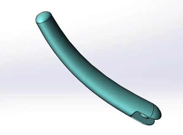
Kick stand is one of the components in bike. It is a piece of metal that flips down from the frame and contacts the ground. It is generally located in the middle of the bike or towards the rear.
COMMANDS: To create the Kick Stand following Features are used.
<!-- [if !supportLists]-->· <!--[endif]-->Loft
<!-- [if !supportLists]-->· <!--[endif]-->Dome
<!-- [if !supportLists]-->· <!--[endif]-->Extrude Cut
<!-- [if !supportLists]-->· <!--[endif]-->Split
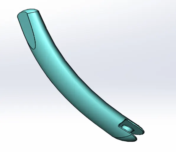
Procedure to create Kick Stand:
Open SolidWorks software-select new part -getting into user interface-select the Front plane LSW (Where the Orientation view of Model you want to see)- Sketch (Normal to the plane)-select ellipse command-exit sketch-select the top plane (MID plane)-select spline command-draw spline by giving dimensions and constraints for fully defined- exit sketch- select loft feature-select two profiles and guide curve-select extrude cut and remove the material from the part-select extrude- select MID plane and select circle command-exit sketch- select plane-draw the line-Split feature and split the part from sketch-click on Appearance-chromium plate cast.
Loft
Loft feature creates a shape by making transitions between multiple profiles and guide curves. This tool is very valuable for modeling complex surfaces.
Dome
Dome feature creates dome-shaped on an existing face of the part. No need to create sketch or revolve for creating round shaped parts in less time.
Extrude Cut
Extrude Cut feature is to remove portion of material from the solid model. This is mainly used for creating holes, channels, slots, etc. When we use the extrude cut feature in SolidWorks, sketch the two-dimensional cross-section of the cut directly on the plane of the part. The cut always goes all the way through the component.
Split
The Split feature is used to create multiple parts from an existing part. You can create separate part files and form an assembly from the new parts. You can split one or more solid or surface bodies. To split a surface, the trimming surface must extend past the boundaries of the surface to split.To split a part, you can make a sketch that intersects the part completely and then click the split.
<!-- [if !supportLists]-->3. <!--[endif]-->FRONT FENDER
Front Fender is an important component of a bike and to protect it from mud, water, and other debris that can be kicked up by the front wheel. It also balances the fforce between the forks in the front of the bike and prevents speed wobbling.
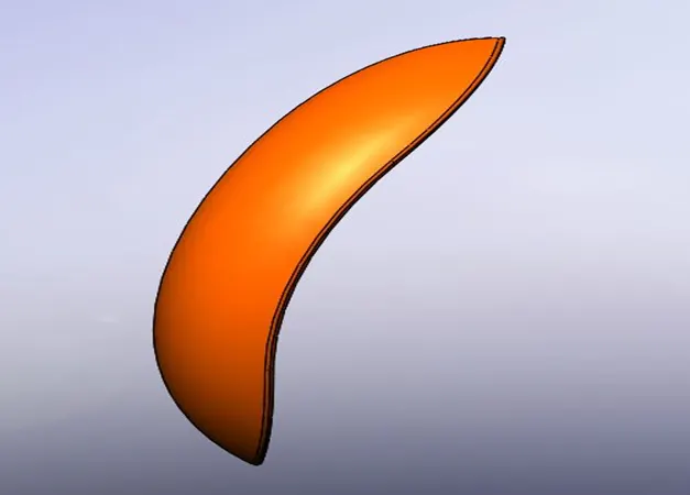
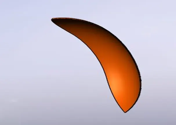
COMMANDS: To create the Front Fender the following Features are used.
<!-- [if !supportLists]-->· <!--[endif]-->Revolve
<!-- [if !supportLists]-->· <!--[endif]-->Split
<!-- [if !supportLists]-->· <!--[endif]-->Fillet
<!-- [if !supportLists]-->· <!--[endif]-->Axis
Procedure to create Front Fender:
Select new part -getting into user interface- Create Axis for center line-select the Front plane LSW (Where the Orientation view of Model you want to see)- Sketch (Normal to the plane)-select line command-exit sketch-select revolve feature and revolve the part. Select top plane and draw the sketch to cut the excess portion using Split feature- Select plane-draw the line-Split feature and split the part from sketch-Add fillet radius for removing sharp edges. Click on Appearance- painted car-Siena.
Revolve
Revolve feature is to create cylindrical shaped models easily and very quickly. We need a sketch with respect to the axis from which the revolve can be created as well as an axis for this sketch to be revolved around.
Axis
An axis is a reference geometry that can be used to create features or mate components in SolidWorks. It is mostly used in assembly configuration. To create axis, you can click axis on the reference geometry tool bar, or click insert-reference geometry-axis. Then, tou can select the axis type and the required entities for that type some of the axis types are : one line /edge/axis, two planes, or two points/ vertices.
REAR FENDER
Rear Fender is an important component of a bike and to protect it from mud, water, and other debris that can be kicked up by the Rear wheel. It also balances the fforce between the forks in the front of the bike and prevents speed wobbling.
COMMANDS: To create the Rear Fender the following Features are used.
<!-- [if !supportLists]-->· <!--[endif]-->Revolve
<!-- [if !supportLists]-->· <!--[endif]-->Split
<!-- [if !supportLists]-->· <!--[endif]-->Fillet
<!-- [if !supportLists]-->· <!--[endif]-->Shell
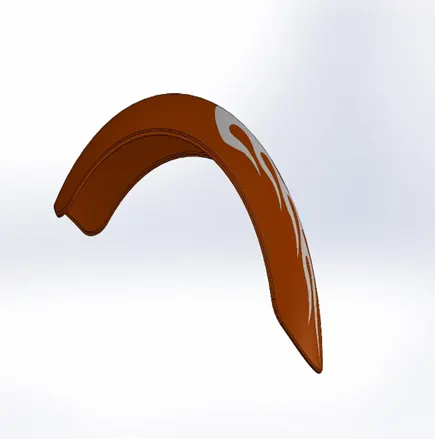
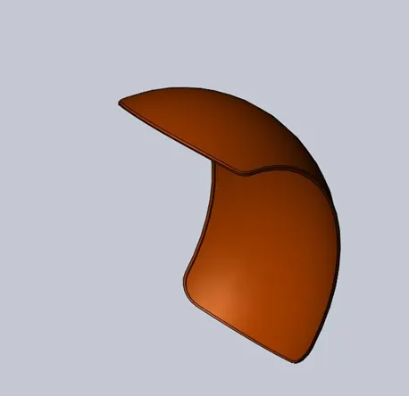
Procedure to create Rear Fender:
Select new part -getting into user interface- Create Axis for center line-select the Front plane LSW (Where the Orientation view of Model you want to see)- Sketch (Normal to the plane)-select line command-exit sketch-select revolve feature and revolve the part. Select top plane and draw the sketch to cut the excess portion using Split feature- Select plane-draw the line-Split feature and split the part from sketch-Add fillet radius for removing sharp edges. Insert-shell feature-select the face and add the thickness. Click on Appearance- painted car-Siena. Appearance-Decals-logo and add it for good looking.
Shell
Shell is the feature that removes the material from inner body of the model and creates hollow or open-faced shape. Shell is used for making pockets, open faces, and thin walls in complex geometry.
<!-- [if !supportLists]-->5. <!--[endif]-->OIL TANK
Oil Tank is used to store engine oil in tank for Gear Box Lubrication and cooling the Engine. Combine two different parts and make a single model by adding shell feature in SolidWorks.
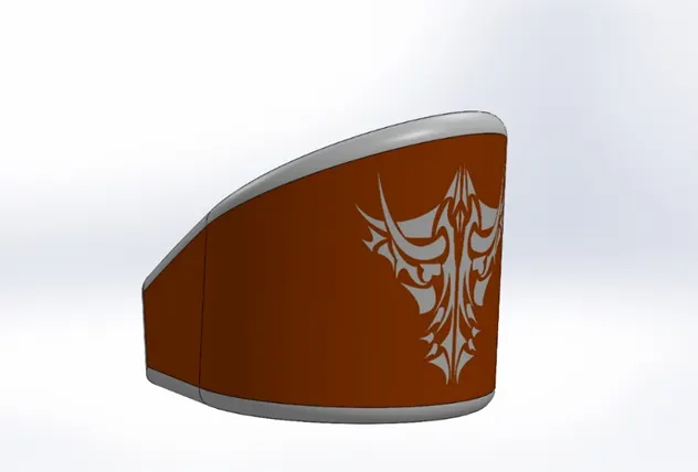
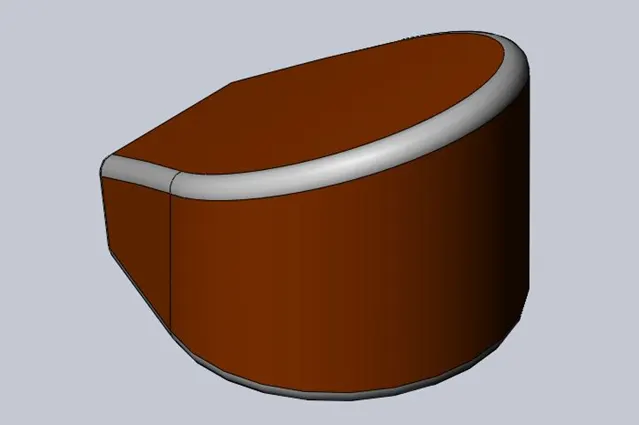
COMMANDS: To create the Oil Tank the following Features are used.
<!-- [if !supportLists]-->· <!--[endif]-->Sketch
<!-- [if !supportLists]-->· <!--[endif]-->Extrude
<!-- [if !supportLists]-->· <!--[endif]-->Combine
<!-- [if !supportLists]-->· <!--[endif]-->Fillet
<!-- [if !supportLists]-->· <!--[endif]-->Shell
Procedure to create Oil Tank:
Select new part -getting into user interface-select the Top plane (Where the Orientation view of Model you want to see)- Sketch (Normal to the plane)-select line command and draw the sketch-exit sketch-select Extrude feature and extruded the part. Select Mid plane oil tank and draw the sketch-exit sketch-select Extrude feature and extruded the part. Insert-combine feature and combine two different models into single part by using operation type as common. Add fillet radius for removing sharp edges. Insert-shell feature-select the face and add the thickness. Click on Appearance- painted car-Siena. Appearance-Decals-logo and add it for good looking.
Combine
The Combining feature is used to combine two bodies in multibody part. We cannot combine two separate part files. We can add, subtract bodies, or keep material that is common to the selected bodies.
<!-- [if !supportLists]-->6. <!--[endif]-->CHAIN
Chain drive is a way of transmitting Mechanical power from driving wheel to driven wheel or one place to another with the help of Gears or Sprockets. Chains are made up of a number of rigid links that are hinged together by pin joints to provide flexibility needed to wrap on sprocket or gears tooth profile.
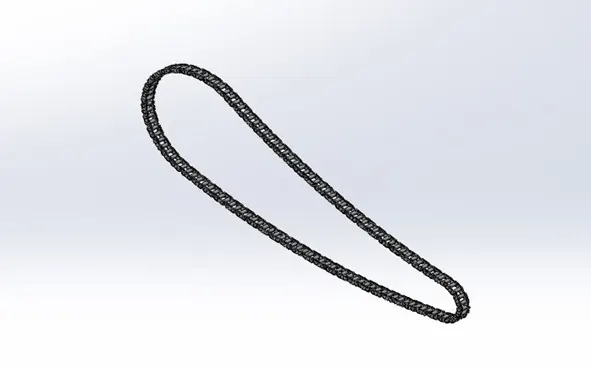
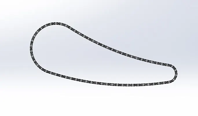
COMMANDS: To create the Chain the following Features are used.
<!-- [if !supportLists]-->· <!--[endif]-->Sketch
<!-- [if !supportLists]-->· <!--[endif]-->Extrude
<!-- [if !supportLists]-->· <!--[endif]-->Fillet
<!-- [if !supportLists]-->· <!--[endif]-->Curve Driven Pattern
<!-- [if !supportLists]-->· <!--[endif]-->Mirror
Procedure to create Chain:
Select new part -getting into user interface-select the Mid plane Chain (Where the Orientation view of Model you want to see)- Sketch (Normal to the plane)-select line command and draw the sketch-exit sketch- select the Mid plane Chain-sketch-select line command and draw the sketch-exit sketch-select Extrude feature and extruded the part. Select Extrude feature and extrude the part. Add fillet radius for removing sharp edges. Select Curve driven pattern-select all bodies which we are going to pattern along with guide curve and same for all chain links. Select Mirror feature-select the Mid plane Chain and mirror all chain links and pins to generate chain. Click on Appearance-color-white.
Mirror
Mirror feature is used to create reflection or mirroring sketch entities about center line in sketching configurations, and faces, features, bodies, and components about plane in part. In assemblies, you can mirror assembly features.
Curve Driven Pattern
The curve driven pattern is a tool that creates pattern of features, faces, or components along a planar or 3D curve.
<!-- [if !supportLists]-->7. <!--[endif]-->PEDAL
Pedals are located in front of footrest for shifting gears from low to high and gives safety for riders.
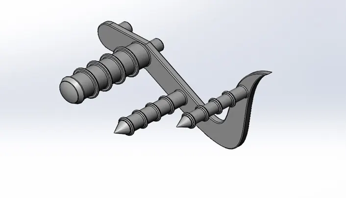
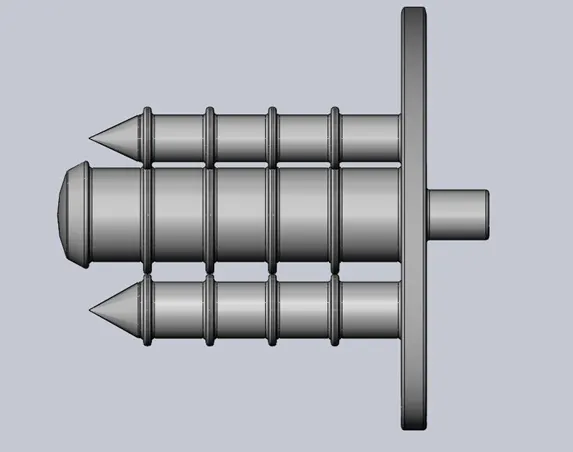
COMMANDS: To create the Pedal the following Features are used.
<!-- [if !supportLists]-->· <!--[endif]-->Sketch
<!-- [if !supportLists]-->· <!--[endif]-->Extrude
<!-- [if !supportLists]-->· <!--[endif]-->Fillet
<!-- [if !supportLists]-->· <!--[endif]-->Linear Pattern
<!-- [if !supportLists]-->· <!--[endif]-->Dome
<!-- [if !supportLists]-->· <!--[endif]-->Chamfer
<!-- [if !supportLists]-->· <!--[endif]-->Appearances
Procedure to create Pedal:
Select new part -getting into user interface-select the Front plane Chopper (Where the Orientation view of Model you want to see)- Sketch (Normal to the plane)-select line command and draw the sketch-exit sketch- select Extrude feature and extruded the part- select the sketch-select line command and draw the sketch-exit sketch-select Extrude feature and extruded the part. Add fillet radius for removing sharp edges. Select the top plane-sketch-select line command and draw the sketch- Select revolve feature and revolve the sketch-To add dome and fillet to the part-Select the sketch and extrude the part add chamfer to it. Select the sketch and extrude the part and add fillet radius. Select Liner Pattern-select the bodies to pattern- Click on ok by adding fillet to it. Click on Appearance-color.
Linear Pattern
To creates Linear pattern instances of one or more features along one or two linear paths by selecting linear edge or dimensioning for spacing for features.
<!-- [if !supportLists]-->8. <!--[endif]-->FRONT WHEEL
The front wheel is driven by using rear wheel. The front wheel, on the hand, steers the motorcycle towards which direction to move. No matter the model or the cc of the motorcycle, the rider always handles and steers the bike through the handlebar and the front wheel. The steering of the front wheel guides the motorcycle to move in the direction intended by the rider. Wheel is made up of rim and tire. Motorcycle wheels are typically composed of steel or aluminum rims but in tubeless tires cast wheels are used for rims.
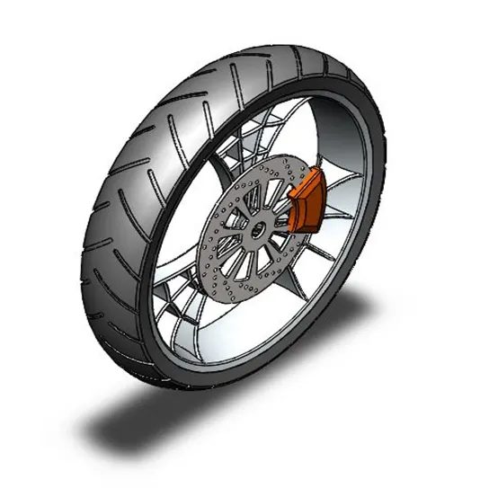
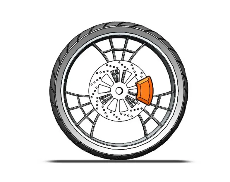
COMMANDS: To create the Front wheel the following Features are used.
<!-- [if !supportLists]-->· <!--[endif]-->Sketch, Line, Spline, Arc
<!-- [if !supportLists]-->· <!--[endif]-->Revolve
<!-- [if !supportLists]-->· <!--[endif]-->Extrude Boss
<!-- [if !supportLists]-->· <!--[endif]-->Extrude Cut
<!-- [if !supportLists]-->· <!--[endif]-->Circular Pattern
<!-- [if !supportLists]-->· <!--[endif]-->Combine
<!-- [if !supportLists]-->· <!--[endif]-->Fillet
<!-- [if !supportLists]-->· <!--[endif]-->Chamfer
<!-- [if !supportLists]-->· <!--[endif]-->Offset
<!-- [if !supportLists]-->· <!--[endif]-->Mirror
<!-- [if !supportLists]-->· <!--[endif]-->Intersection Curve
Procedure to create Front wheel:
Select new part-getting into user interface-select the Front plane Chopper (Where the Orientation view of Model you want to see)- Sketch (Normal to the plane)-select line command and draw the sketch-exit sketch- select Revolve feature and revolve the part- select the Right plane-sketch- select line and spline command and draw the sketch-exit sketch- rim spokes are created. select the Right plane-sketch- select line and spline command and draw the sketch-exit sketch-select Extrude cut feature and cut the part and making small rim spokes are created. select the Right plane-sketch- select line, arc, circle and draw the sketch look like spider web design or cobweb shape-exit sketch- Select Extrude boss feature and extruded the part and making strengthen to spokes. select the Front plane Chopper-Select intersection curve feature from convert entities-select inside rim gives arc and select line, arc, spline command and draw the sketch-exit sketch-select revolve cut feature and cut the part. Select circular pattern-select spokes of the by referencing edge of the rim and makes three spokes. Combine three spokes, hub, rim and make single part. Add fillet radius for removing sharp edges. Select the Right plane-sketch- select line and draw the sketch- exit sketch-select Extrude cut feature and cut the part. Select Extrude boss feature and extrude the part and makes rotor. Select the front face of the rotor and make holes for caliper. Select front face of the rotor-select the line and draw the sketch- Add fillet radius for removing sharp edges. select the Right plane-sketch- select circle command and draw the sketch-exit sketch-select Extrude cut feature and cut the part. Select the front face of the rotor and select circle command and draw the sketch-exit sketch-select Extrude feature and make caliper. select the Right plane-sketch- select line and arc command and draw the sketch-exit sketch-select revolve feature and make tire. Select the Front plane Chopper and create gripping cuts for wheel by revolve pattern. Click on Appearance- for tire using Matte rubber, for caliper using painted car Siena and for Rim, Rotor, Sprocket using metal-chrome-chromium plate.
Circular Pattern
To creates Circular pattern instances of one or more features along with circular path by selecting circular edge or circular face for features.
Intersection Curve
Convert Entities are mostly used for creating sketches from existing part. Intersection curve created by selecting round face or circular face of existing part.
<!-- [if !supportLists]-->9. <!--[endif]-->REAR WHEEL
The power generated by the motorcycle engine is all fed to the back tire of the bike. The rear wheel acts as the moving force behind the motorcycle that propels the bike forwards. Choosing to use a broader or thicker wheel is preferable, as the thicker back wheel helps increase the wheel’s surface area that comes into contact with the road.
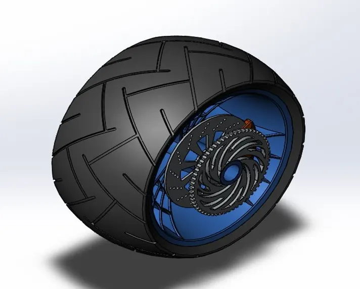
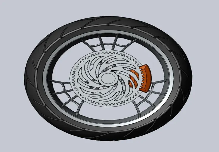
COMMANDS: To create the Rear wheel the following Features are used.
<!-- [if !supportLists]-->· <!--[endif]-->Sketch, Line, Spline, Arc
<!-- [if !supportLists]-->· <!--[endif]-->Revolve
<!-- [if !supportLists]-->· <!--[endif]-->Extrude Boss
<!-- [if !supportLists]-->· <!--[endif]-->Extrude Cut
<!-- [if !supportLists]-->· <!--[endif]-->Circular Pattern
<!-- [if !supportLists]-->· <!--[endif]-->Combine
<!-- [if !supportLists]-->· <!--[endif]-->Fillet
<!-- [if !supportLists]-->· <!--[endif]-->Chamfer
<!-- [if !supportLists]-->· <!--[endif]-->Offset
<!-- [if !supportLists]-->· <!--[endif]-->Mirror
<!-- [if !supportLists]-->· <!--[endif]-->Intersection Curve
Procedure to create Rear wheel:
Same as front wheel in addition to that Sprocket is added to the rear wheel. Select outside face of the axle-select circle command and draw the sketch-Extrude the circle and create sprocket-For sprocket teeth select outside face of sprocket - select line and arc command, draw the sketch-Extrude cut the tooth profile and create sprocket teeth. Click on Appearance- for tire using Matte rubber, for caliper using painted car Siena and for Rim, Rotor, Sprocket using metal-chrome-chromium plate.
<!-- [if !supportLists]-->10. <!--[endif]-->FRONT FORK
A motorcycle fork connects a motorcycle's front wheel and axle to its frame, typically via a yoke, also known as a triple clamp, which consists of an upper yoke joined to a lower yoke via a steering stem, a shaft that runs through the steering head, creating the steering axis. Most forks incorporate the front suspension and front brake, and allow the front wheel to rotate about the steering axis so that the bike may be steered. Most handlebars attach to the top clamp in various ways, while clip-on handlebars clamp to the fork tubes, either just above or just below the upper triple clamp.
The fork and its attachment points on the frame establish the critical geometric parameters of rake and trail, which play a major role in defining how a motorcycle handles and dives during braking.
There are three main types of motorcycle front Forks:
<!-- [if !supportLists]-->v <!--[endif]-->Telescopic Forks
<!-- [if !supportLists]-->v <!--[endif]-->Leading Link Forks
<!-- [if !supportLists]-->v <!--[endif]-->Trailing Link Forks
Telescopic Forks
A telescopic fork uses fork tubes which contain the suspension components (coil springs and damper) internally. This is the most common form of fork commercially available. It may or may not include gaiters for protection against abrasive elements on the suspension cylinders. The main advantages of the telescopic fork are that (i) it is simple in design and relatively cheap to manufacture and assemble; (ii) it is lighter than older designs using external components and linkage systems; and (iii) it has a clean and simple appearance that bikers find attractive.
Conventionally, the fork stanchions are at the top, secured by a yoke (also called a triple tree or a triple clamp), and the sliders are at the bottom, attached to the front wheel spindle. On some modern sport bikes and most off-road bikes, this system is inverted, with "sliders" (complete with the spring/damper unit) at the top, clamped to the yoke, while the stanchions are at the bottom. This is done (i) to reduce unspring weight by having the heavier components suspended, and (ii) to improve the strength and rigidity of the assembly by having the strong large diameter "sliders" clamped in the yokes.
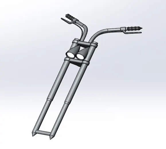
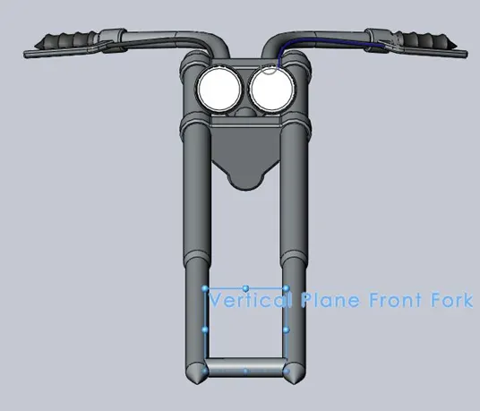
COMMANDS: To create the Front Fork the following Features are used.
<!-- [if !supportLists]-->· <!--[endif]-->Sketch, Line, Spline, Arc
<!-- [if !supportLists]-->· <!--[endif]-->Revolve
<!-- [if !supportLists]-->· <!--[endif]-->Extrude Boss
<!-- [if !supportLists]-->· <!--[endif]-->Extrude Cut
<!-- [if !supportLists]-->· <!--[endif]-->Linear Pattern
<!-- [if !supportLists]-->· <!--[endif]-->Combine
<!-- [if !supportLists]-->· <!--[endif]-->Fillet
<!-- [if !supportLists]-->· <!--[endif]-->Chamfer
<!-- [if !supportLists]-->· <!--[endif]-->Offset
<!-- [if !supportLists]-->· <!--[endif]-->Mirror
<!-- [if !supportLists]-->· <!--[endif]-->Dome
<!-- [if !supportLists]-->· <!--[endif]-->Projected Curve
<!-- [if !supportLists]-->· <!--[endif]-->Intersection Curve
<!-- [if !supportLists]-->· <!--[endif]-->Body Move/Copy
<!-- [if !supportLists]-->· <!--[endif]-->Sweep Boss Base
Procedure to create Front Fork:
Create Telescope forks for Chopper-Select new part-getting into user interface-select the Front plane Chopper (Where the Orientation view of Model you want to see)- Sketch (Normal to the plane)-select line command and draw the sketch-exit sketch- select Revolve feature and revolve the part(fork tube)- select upper end of the tube-sketch- select line and circle command and draw the sketch-exit sketch-select Extrude boss feature and extruded the part Triple clamp created. Add fillet radius for removing sharp edges. Click on the glasses icon and turn on the temporary axis. select the Linear pattern-select temporary axis and pattern triple clamp. select the Front plane Chopper-sketch-circle command and draw the sketch-exit sketch-select Extrude feature and extrude the part. select the Front plane Chopper -sketch- select line, arc, and draw the sketch -exit sketch-Select Revolve feature and make headlight bucket and add cut, fillet, dome to the head. select upper face of top triple clamp-select circle command and draw the sketch-exit sketch-select top plane-sketch-spline command and draw the sketch-exit sketch-select front plane-sketch-spline command and draw the sketch-exit sketch-Curves-Projected curve-sketch on sketch-click on ok. Select-Swept boss base-select the projected sketch and circle-create handlebar with clutch liver-create cable by two different sketches from top and front plane with projected curve options. Swept boss base-select the projected sketch and circle. Select Mirror Feature-select bodies to mirror-Triple clamp, fork, handlebar with cables, axle, head lights-click on merge solids option. Appearances-metal-chrome-polished chrome for bodies- rubber-glass rubber for brake lines and handle liver. Select Lense and chamfer-Appearances-lights-Area light option-click on ok. Render tabs-preview window appears bright light coming from Lense. Now completed Front fork.
Projected Curve
A project curve is a type of curve in SolidWorks used to create Project curve from 2D and 3D sketches, onto faces and planes. Selecting two different sketches from two planes or faces gives a project curve.
<!-- [if !supportLists]-->11. <!--[endif]-->CHASSIS
Chassis is Main component of the Motorcycle. Chassis makes a single component for strength, reliability, and better performance of the bike. It can withstand All the components of a motorcycle, like the suspension, wheels, fuel tank, seats, handlebars etc., are attached to this base structure which lends a motorcycle its strength and ability to handle well. It also houses the steering equipment in the front with the help of a steering head tube. Frames were commonly made from steel; however, manufacturers now also use long-lasting materials such as Titanium, Magnesium, Carbon Fiber, etc., depending upon requirements and production costs.

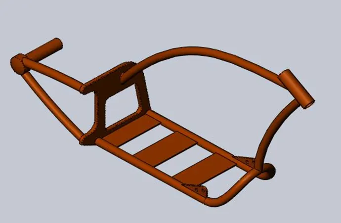
There are various types of chassis in motorcycles. Including
<!-- [if !supportLists]-->v <!--[endif]-->Backbone frame
<!-- [if !supportLists]-->v <!--[endif]-->Single Cradle Frame
<!-- [if !supportLists]-->v <!--[endif]-->Double Cradle Frame
<!-- [if !supportLists]-->v <!--[endif]-->Perimeter Frame
<!-- [if !supportLists]-->v <!--[endif]-->Trellis Frame
<!-- [if !supportLists]-->v <!--[endif]-->Monocoque
COMMANDS: To create the Chassis the following Features are used.
<!-- [if !supportLists]-->· <!--[endif]-->Sketch Picture
<!-- [if !supportLists]-->· <!--[endif]-->Project Curve
<!-- [if !supportLists]-->· <!--[endif]-->Sweep
<!-- [if !supportLists]-->· <!--[endif]-->Mirror
<!-- [if !supportLists]-->· <!--[endif]-->Chamfer
<!-- [if !supportLists]-->· <!--[endif]-->Extrude Boss
<!-- [if !supportLists]-->· <!--[endif]-->Extrude Cut
<!-- [if !supportLists]-->· <!--[endif]-->Fillet
Procedure to create Chassis:
Create Chassis for Chopper-Select new part-getting into user interface-select the Middle plane Chopper (Where the Orientation view of Model you want to see)- Sketch (Normal to the plane)-select Tools-Sketch Tools- Sketch Picture and give the dimensions for x, y, z- select the Middle plane Chopper-sketch-select circle-exit sketch. select the Middle plane Chopper-sketch-select line and spline command-exit sketch. select the Bottom plane Chopper-sketch-select line and spline command-exit sketch. Feature tab-Curves-Project curve-select two sketches-ok. select the right plane Chopper-sketch-select spline command-exit sketch. select the Bottom plane Chopper-sketch-select line and convert entities-exit sketch. Select swept features- select two sketches-ok. Mirror-select the Middle plane Chopper-sketch-select swept body-ok. select the right plane Chopper-sketch- select line and circle-exit sketch- extrude boss-ok. Select the back side of bottom plate-sketch- line and offset command-exit sketch- Extrude cut-select sketch-ok. Create plane-select the plane-sketch-select Spline command- Select swept feature and create tubes for entire chassis. Apply -fillet and chamfer for all edges. Appearance -metal-car-painted car.
<!-- [if !supportLists]-->12. <!--[endif]-->ENGINE
Engine is the main part of the vehicle. Engine that powers a motorcycle by converting Thermal energy to mechanical power with the help of fuel. Motorcycle engines are two stroke or four stroke internal combustion engines. They consist of pistons, a cylinder block and a head, which contains the valve train. The piston moves up and down in the cylinder block, driven by explosions of a fuel air mixture that has been ignited by a spark. Valves open and close to allow the fuel-air mixture to enter the combustion chamber. As the pistons move up and down, they turn a crankshaft, which transforms the energy from the pistons into rotary motion. The rotational force of the crankshaft is transmitted, via the transmission, to the rear wheel of the motorcycle. In four stroke petrol engines having four strokes. They are 1) Intake Stroke 2) Compression Stroke 3) Expansion or Power Stroke 4) Exhaust Stroke
Compression Ratio: The ratio between the volume of the cylinder and combustion chamber in an internal combustion engine at their maximum and minimum values.
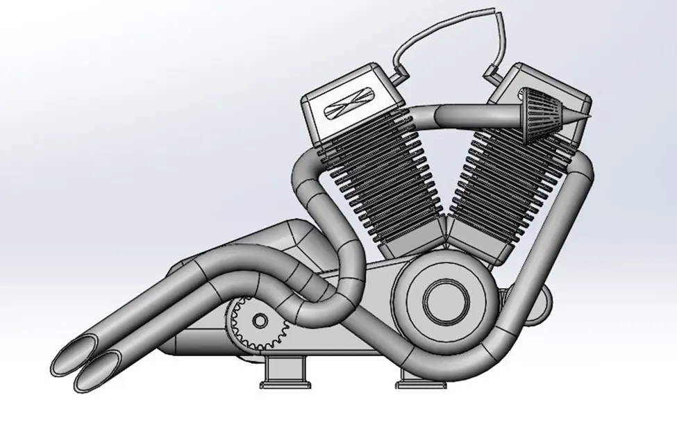
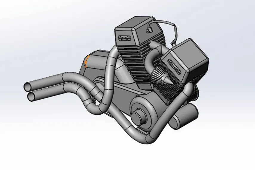
COMMANDS: To create the Engine the following Features are used.
<!-- [if !supportLists]-->· <!--[endif]-->Sketch Picture
<!-- [if !supportLists]-->· <!--[endif]-->Project Curve
<!-- [if !supportLists]-->· <!--[endif]-->Sweep
<!-- [if !supportLists]-->· <!--[endif]-->Mirror
<!-- [if !supportLists]-->· <!--[endif]-->Chamfer
<!-- [if !supportLists]-->· <!--[endif]-->Extrude Boss
<!-- [if !supportLists]-->· <!--[endif]-->Extrude Cut
<!-- [if !supportLists]-->· <!--[endif]-->Fillet
<!-- [if !supportLists]-->· <!--[endif]-->Circular Pattern
<!-- [if !supportLists]-->· <!--[endif]-->Linear Pattern
<!-- [if !supportLists]-->· <!--[endif]-->Dome
<!-- [if !supportLists]-->· <!--[endif]-->Revolve
<!-- [if !supportLists]-->· <!--[endif]-->Split
<!-- [if !supportLists]-->· <!--[endif]-->Combine
<!-- [if !supportLists]-->· <!--[endif]-->Composite Curve
13. <!--[endif]-->GASTANK
In Petrol or Gasoline and Diesel vehicles, we have Fuel storage tank for storing the fuel. Mostly, Fuel tanks are fabricated by Mild steel sheet or Stainless steel. The Size and Shape of a motorcycle’s Gas tank are crucial factors that impact its fuel capacity. Tanks with irregular shapes or narrow necks may be more challenging to fill up to their full capacity. Additionally, tanks with deeper profiles may hold more fuel than tanks with shallower profiles.
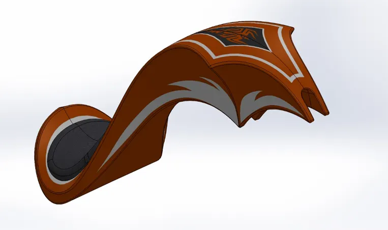
COMMANDS: To create the Gas tank the following Features are used.
<!-- [if !supportLists]-->· <!--[endif]-->Sketch Picture
<!-- [if !supportLists]-->· <!--[endif]-->Surface Sweep
<!-- [if !supportLists]-->· <!--[endif]-->Surface Trim
<!-- [if !supportLists]-->· <!--[endif]-->Surface Loft
<!-- [if !supportLists]-->· <!--[endif]-->Boundary Surface
<!-- [if !supportLists]-->· <!--[endif]-->Knit Surface
<!-- [if !supportLists]-->· <!--[endif]-->Project Curve
<!-- [if !supportLists]-->· <!--[endif]-->Sweep cut
<!-- [if !supportLists]-->· <!--[endif]-->Mirror
<!-- [if !supportLists]-->· <!--[endif]-->Extrude Surface
<!-- [if !supportLists]-->· <!--[endif]-->Chamfer
<!-- [if !supportLists]-->· <!--[endif]-->Fillet
<!-- [if !supportLists]-->· <!--[endif]-->Split line
<!-- [if !supportLists]-->· <!--[endif]-->Composite Curve
14. <!--[endif]-->ASSEMBLY
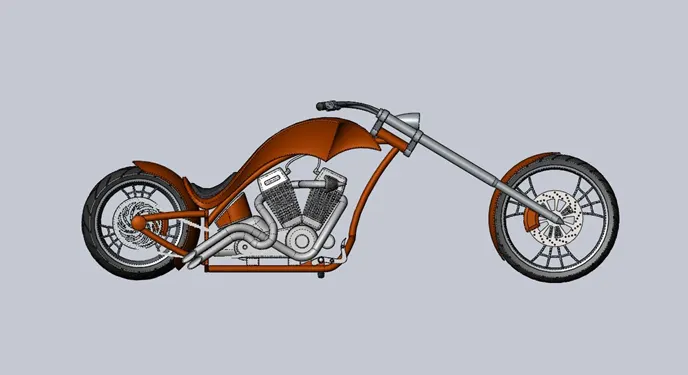
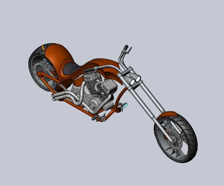
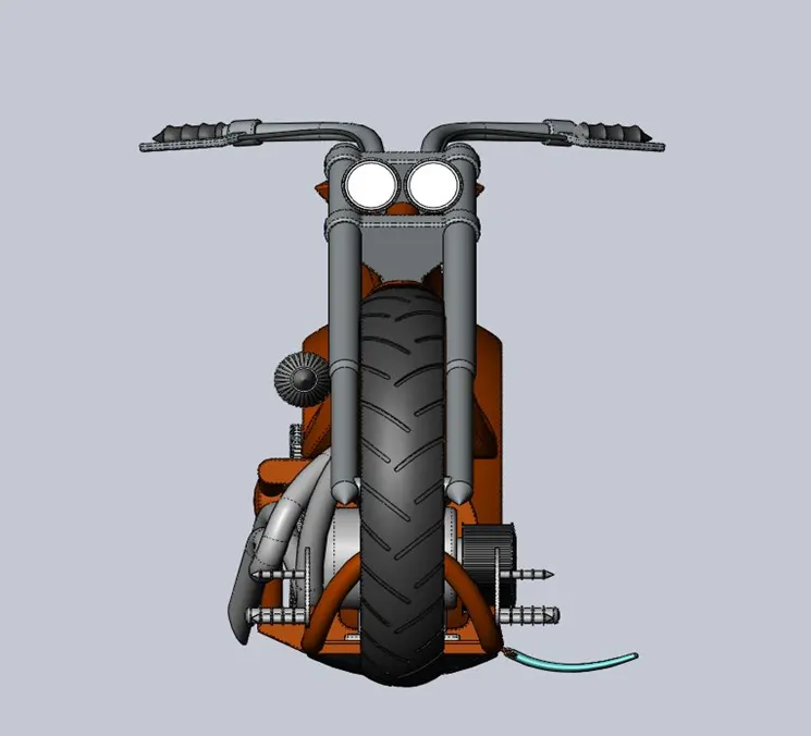
It is a design methodology in which all parts are designed independently without any reference in assembly. In this project all parts are modelled individually and assembled together by Bottom-up approach. Chassis is the main part for constructing base giving strength to the vehicle.
A chassis withstands all the weight of the vehicle in the center, so, it is always fixed. In SolidWorks, Chassis is a fixed component and the remaining components in the assembly are movable (float).
<!-- [if !supportLists]-->15. <!--[endif]-->RENDERING
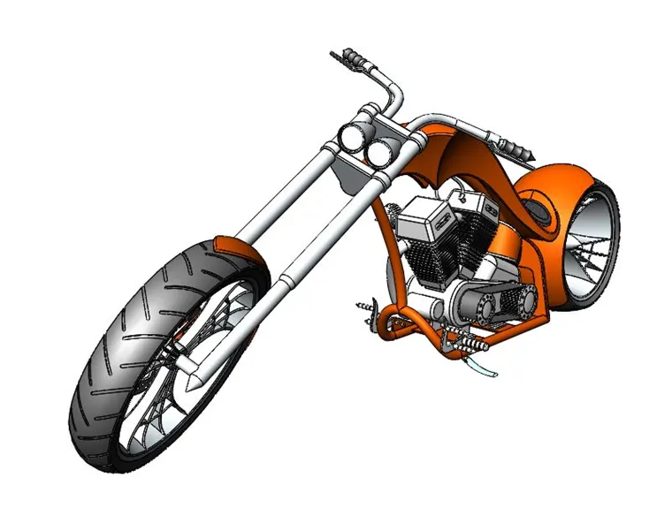
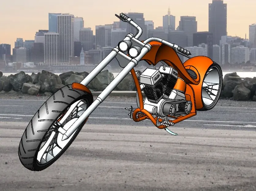
In this project, finally created realistic views of American Chopper. It is a very important part because of different materials, colors, etc. to be applied to assembly one. Here, the product to be seen under environmental conditions with different views. To open the final render window. Enable photo view 360 and click photo view 360- Final render or click final render on the render tools tab of the command manager. Realistic views of American chopper created in SolidWorks by adding Lights, Camera, Scenes with different background images.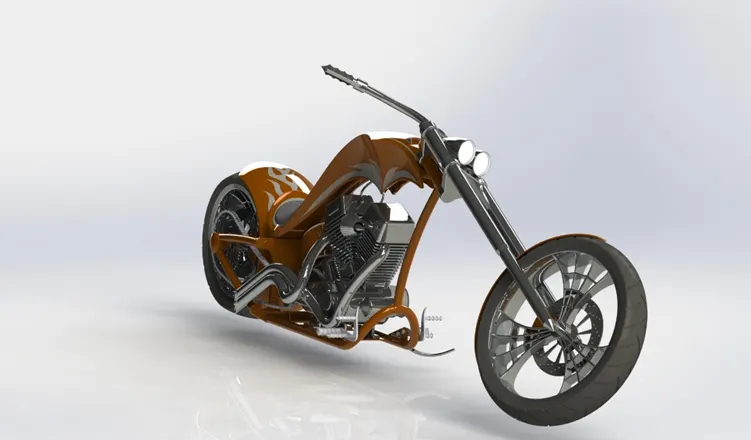
<!-- [if !supportLists]-->16. <!--[endif]-->CONCLUSION
Parts, Assembly and Photo Realistic Rendering of Customized American Chopper Completed. In American Chopper, The Rake angle is 59̊ (Degrees) this gives more stylish for looking. Lights, Camera Scenes, and background environment added to chopper this makes it more realistic and friendly for rider.
https://drive.google.com/drive/folders/1Yn5hYVywuj2EjysGANMXjcxyvP615OHC?usp=drive_link