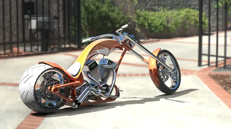
AMERICAN CHOPPER
SolidWorks is a solid modelling computer-aided design (CAD) and computer-aided engineering (CAE) application published by Dassault Systems. In this project I learnt how to design 3D models of various parts of an American Chopper in Solidworks, assembling the individual parts together and rendering them using Solidworks Visualize to give the final look and feel to our model by adding backgrounds , enhancing the colours as well the lighting .
DESIGN METHODOLOGY
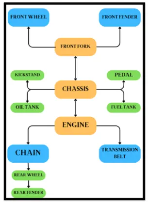
MOST COMMON COMMANDS USED FOR MODELLING IN SOLIDWORKS
EXTRUDE :
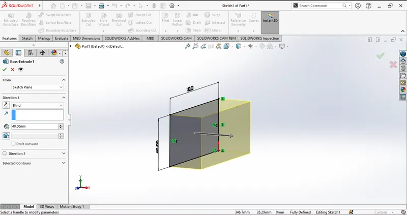
In SolidWorks, the Extrude feature is a commonly used tool for transforming 2D sketches into 3D objects. You can find the Extruded Boss/Base feature in the features tab of the command manager interface. However, it's important to note that the Extruded Boss/Base feature requires a fully enclosed sketch and does not accept open sketches. When using this feature, you need to select the specific surface you want to extrude by clicking on it. This allows you to generate the desired 3D shape by extending the selected surface in the extrusion direction.
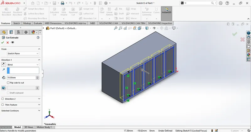
EXTRUDE CUT :
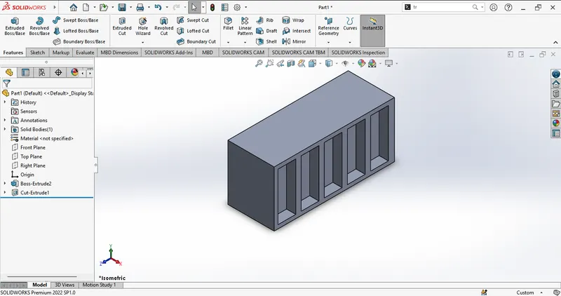
The Extrude Cut is a solidworks feature tool which is used to create cuts in 3D Objects .
REVOLE:
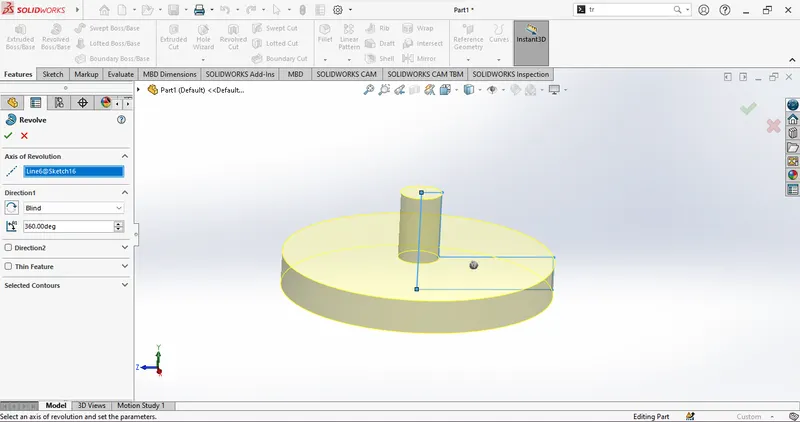
The Revolved Boss/Base feature in SolidWorks is a tool that enables the creation of solid 3D models by revolving a 2D sketch around an axis. This process converts the sketch into a 3D shape. It is not limited to creating solid objects only, as you can also generate revolve cuts and revolved surfaces. Whether you need a solid, thin feature, or a surface, the Revolved Boss/Base feature can accommodate your requirements.
SWEEP :
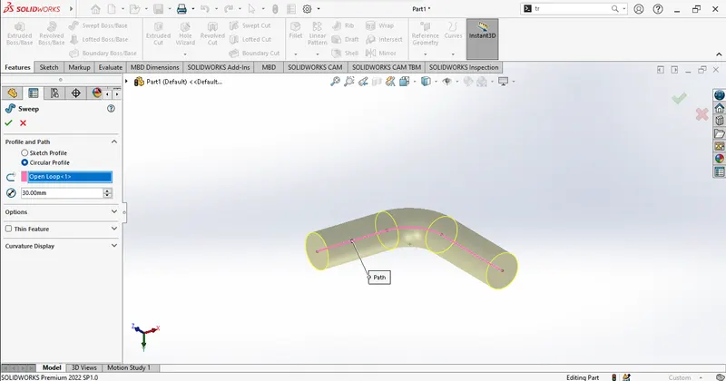
In SolidWorks, the Sweep feature is used to create a 3D feature by sweeping a profile along a defined path. It allows you to create complex shapes and designs by controlling the orientation and size of the profile as it moves along the path.
MIRROR:
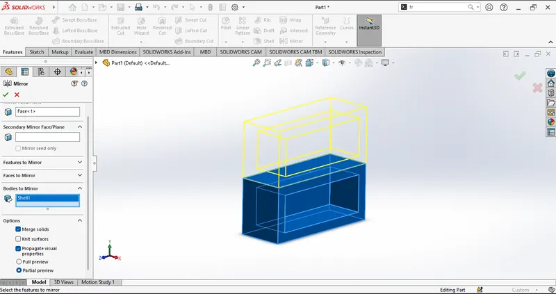
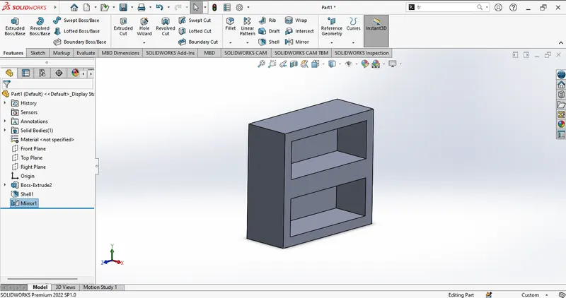
The Mirror command in SolidWorks is a valuable tool used to replicate sketch entities, features, faces, bodies, and components by creating a mirrored version based on a reference line or plane. This feature is particularly useful when you need to generate two objects that possess the same dimensions, shape, and size with respect to a specific reference. By utilizing the Mirror command, you can efficiently create symmetrical designs. or duplicate components with ease.
LINEAR/CIRCLE PATTERN :
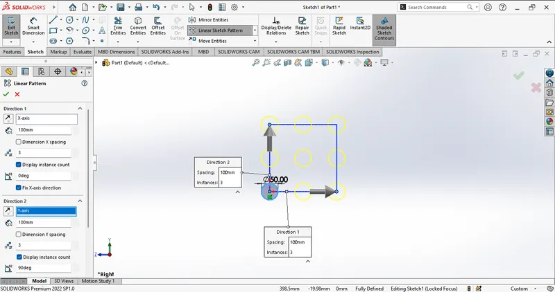
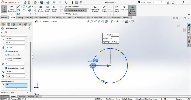
Linear and Circular patterns in SolidWorks are utilized to generate multiple repetitions of one or more features, which can be uniformly spaced along specified paths or axes. Linear patterns allow you to create instances along a linear path, while Circular patterns create instances around an axis, enabling rapid and efficient replication of features. By utilizing these pattern features, you can easily and swiftly produce a series of identical elements along a straight line or around a central axis, saving valuable time and effort.
SHELL :
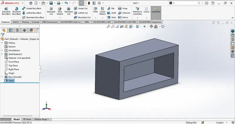
The Shell feature in SolidWorks enables the creation of hollowed-out sections within a solid object, resulting in thin-walled features on the remaining surfaces. It allows you to generate a closed, hollow model by simply applying the Shell feature without selecting any specific geometry. Additionally, you have the flexibility to shell a model using multiple thicknesses, providing further design possibilities. This tool is highly convenient as it eliminates the need for an extrude cut and provides an efficient way to create internal hollow spaces within a part.
FILLET :
The Fillet tool in SolidWorks is designed to generate rounded edges on both internal and external faces of a part. It is particularly useful for achieving a smooth and rounded appearance at the intersections where two or more corners meet. With the Fillet tool, you have the flexibility to apply fillets to all edges of a face, specific sets of a face, selected edges, or even edge loops. By applying fillets, you can enhance the aesthetics of your design and ensure a clean and visually appealing junction between different components or surfaces.
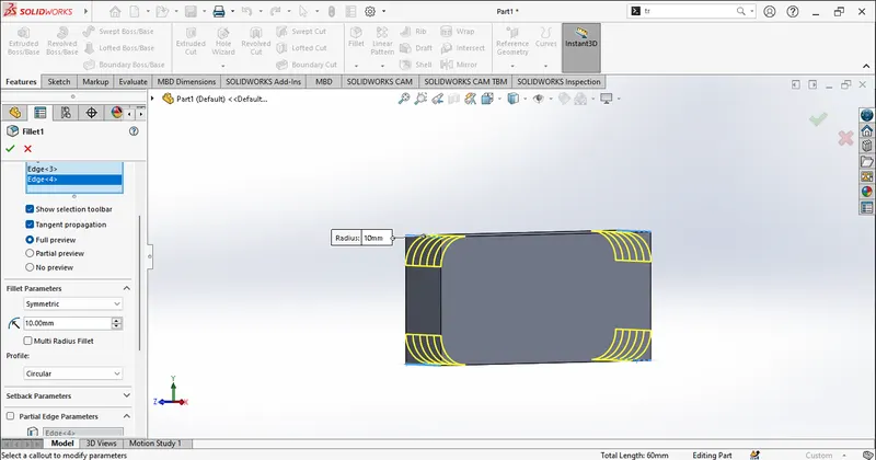
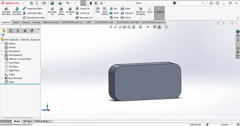
CHAMFER :
The Chamfer tool in SolidWorks is used to create a sloped edge between two primary faces of a part, allowing for easier joining with another component. By specifying the distance and angle of the chamfer directly in the graphics area, you can customize the shape of the chamfer according to your requirements. The main purpose of using the Chamfer tool is to remove sharp edges, providing a smoother transition and reducing the risk of sharp corners or edges that could cause injury or interference. Chamfers help enhance the overall aesthetics of a design while improving functionality and safety.
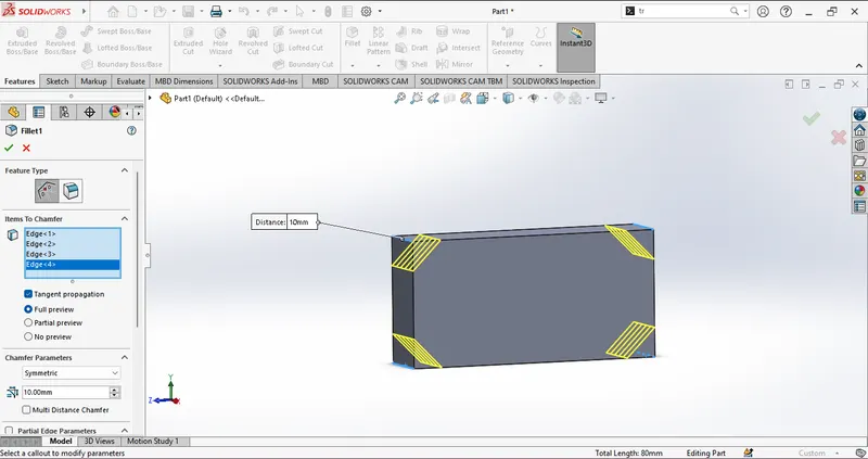
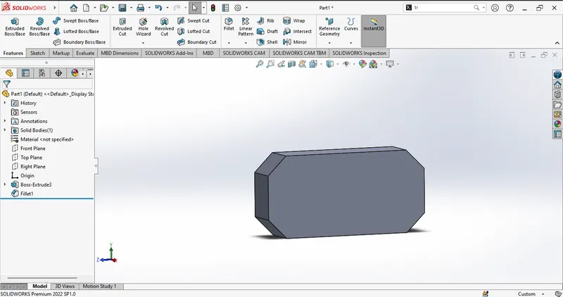
PROJECTED CURVES :
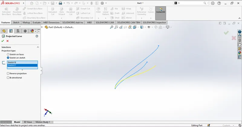
The Projected Curve feature is utilized to generate 3D curves by projecting two intersecting 2D curves from separate planes.
MODELLING THE CHOPPER
Transmission Belt:
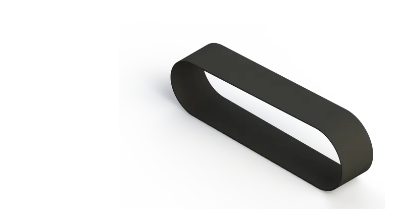
A transmission belt serves the purpose of connecting multiple rotating shafts, enabling the transfer of power. It acts as a means of transmitting motion and power between components. The belt is typically wrapped around pulleys to facilitate power transmission. In the process of modeling the transmission belt, fundamental tools like extrude and fillets were employed to create the desired shape and features.
Kickstand:
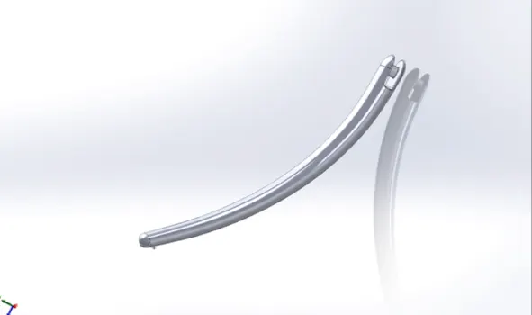
A kickstand is a device on a bike that provides stability by allowing it to stand upright without leaning against other objects or requiring the assistance of a person. It typically consists of a metal piece that can be flipped down from the bike's frame to make contact with the ground. In the process of modeling this kickstand, the loft feature was used to create the main structure, while domes were added at both ends of the object. Cut extrude was employed to remove unnecessary faces, and finally, extrude and fillet features were applied to complete the model.
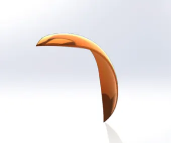
Front and Rear Fenders:
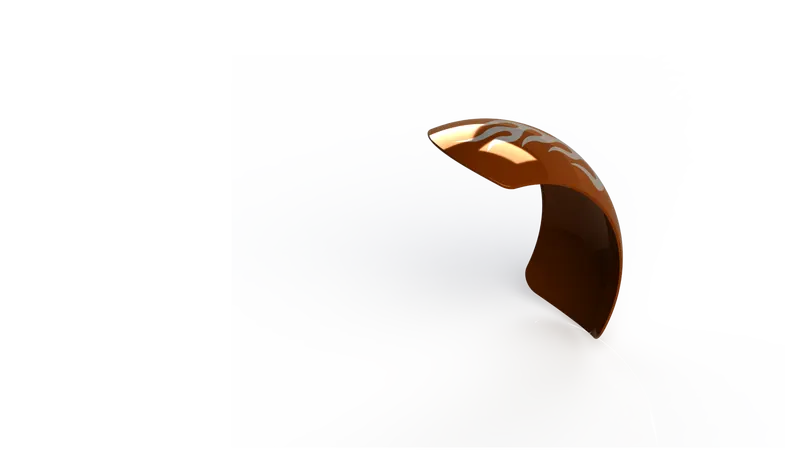
- Fenders, commonly referred to as mudguards, have a primary function of shielding against the projection of sand, mud, rocks, liquids, and road spray caused by the rotating tires. The kinetic energy of the tire can forcefully eject these materials into the air.
- To create these fenders, the revolve and split tools were utilized in the modeling process. Fillets were added to provide a sleek and polished appearance.
- While both fenders share the same visual design, they may differ in terms of dimensions and size.
Chain:
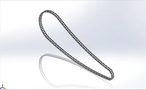
- The chain plays a crucial role in the drivetrain as it transfers power from the motor to the rear wheel. When properly lubricated, chains can achieve transmission efficiencies of 98% or higher. However, the performance of the chain can be compromised if it is not adequately lubricated.
- Modeling the chain was a challenging task, requiring careful assembly of numerous intricate components. To streamline the process, the curve driven pattern and mirror commands proved invaluable, enabling rapid and easy modeling.
- The links of the chain were created as blocks and then carefully inserted, ensuring precise alignment and connection.
Oil Tank:
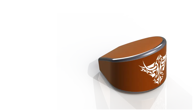
- An oil tank is an essential component for any vehicle, even in the case of electric vehicles. It is responsible for supplying a continuous flow of oil to the engine for proper functioning.
- Creating the oil tank was a straightforward process. The model was made hollow using a combination of the Combine feature and the Shell tool. Fillets and extrudes were also incorporated to enhance the design and ensure a smooth transition between surfaces.
Pedal:
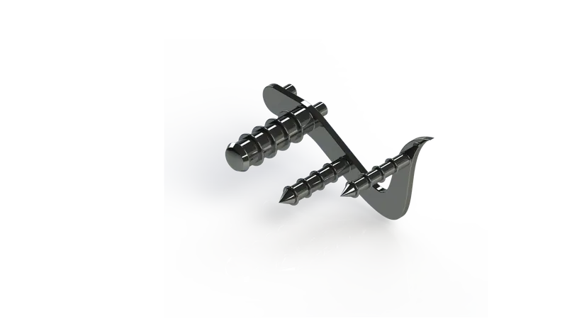
The pedal is a robust and immovable component primarily utilized as a footrest in motorcycles. To enhance its functionality, linear pattern was employed to create grooves on the surface. Various tools such as domes, fillets, and chamfers were utilized to provide a smooth and uniform appearance to the model.
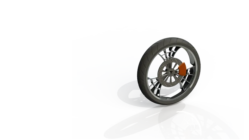
Front Wheel:
- The front wheel of a vehicle typically has a larger diameter compared to the rear wheel. It is important to exercise caution when applying brakes to the front wheel, as they possess significant stopping power that, if used incorrectly, can lead to accidents.
- To achieve a visually appealing layout for the alloys, a special spider web design was implemented. This design was created by utilizing offsets and three-point arcs. The brake caliper and rotor components were then constructed using the extrude feature.
- Finally, the tire was modeled by employing the revolve tool, and treads were inserted and given a circular pattern to enhance realism and functionality.
Rear Wheel:
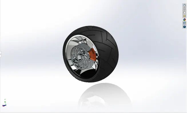
- The rear wheel plays a crucial role in receiving power from the engine and assisting in the acceleration of the vehicle. In order to maintain balance, the rear wheel of a chopper is noticeably wider than the front wheel.
- The addition of a sprocket was required for the rear wheel, in addition to the parts used to construct the front wheel. The chain is connected to the sprocket, facilitating power transmission.
- The design of the alloys for the rear wheel follows the same pattern and design as that of the front wheel, ensuring consistency in the overall appearance of the motorcycle.
Front Fork:
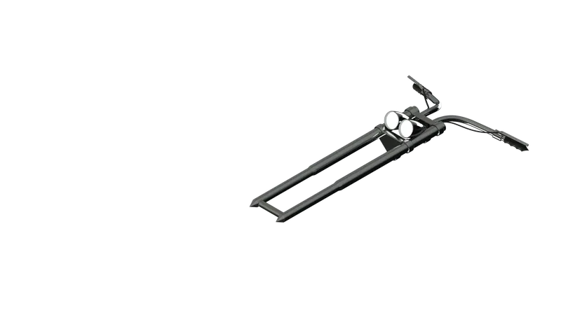
- Front forks serve two primary purposes: front suspension and front brake operation. They enable the front wheel to rotate smoothly around the steering axis, allowing for effective steering of the bike.
- To create the brake wire, projected curves were employed, ensuring proper alignment and functionality. The mirroring technique expedited the finishing process of the part, resulting in efficient and accurate replication.
- Special attention was given to the design of the headlights, enhancing their appearance to emit a vibrant and luminous glow. This meticulous detailing adds to the overall aesthetic appeal and functionality of the bike.
Chassis:
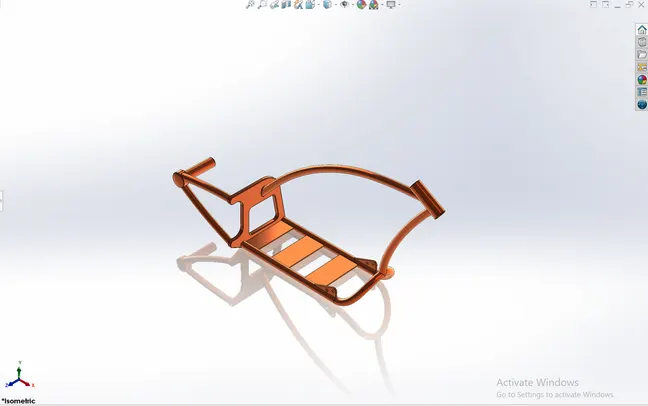
The chassis serves as the foundation of the motorcycle, providing a framework that supports various components including the wheels, fuel tank, seat, engine, and more. To create the model, a reference chopper sketch was used as a starting point.The process involved the use of tools such as sweep, mirror, split, and splines. While it required a significant amount of time, the creation of the chassis was relatively straightforward.
Engine:
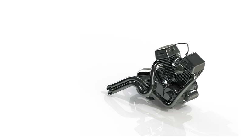
- The engine is an indispensable component for any vehicle, often referred to as the "heart" of the vehicle. It is a mechanical device that converts energy from fuel into mechanical energy to power the vehicle.
- The modeling process for this part was a time-consuming endeavor.
- To create the exhaust, projected curves were employed to ensure accurate representation. Pulleys were constructed to accommodate the transmission belt.
- Fins were added to the upper part, and the mirroring technique facilitated a more efficient workflow.
- Spark plugs were also modeled using a combination of the sweep and splines tools, resulting in their accurate representation within the engine assembly.
Gas Tank:
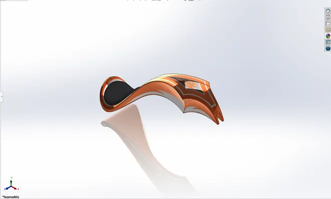
- The gas tank plays a crucial role in shaping the vehicle, as it defines its overall appearance. The oil tank's access is typically located within the gas tank. In this particular model, the seat is positioned atop the gas tank, creating a unique design.
- Creating this part required referencing an image to ensure accurate representation. A variety of tools, including surface knit, surface loft, and cut sweep, were utilized during the modeling process. These tools allowed for the creation of complex surfaces and precise cuts, resulting in the desired shape and functionality of the gas tank.
ASSEMBLING THE CHOPPER
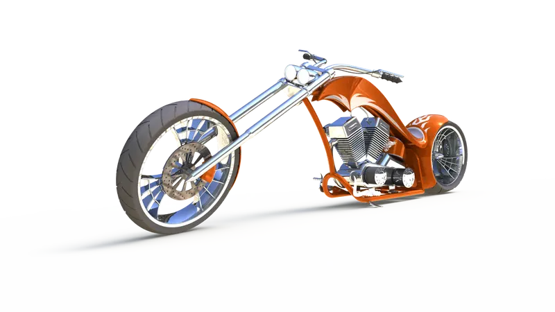
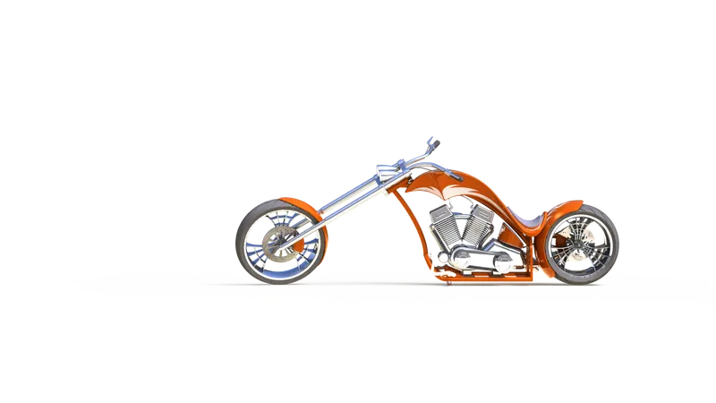
The assembly process of the chopper was the most captivating and thrilling part of the entire creation for me. The assembly was accomplished by applying various mates, such as parallel, coincident, and concentric, to different faces and components. Since the chassis serves as the skeleton of the vehicle, it was inserted as the first component in the assembly.
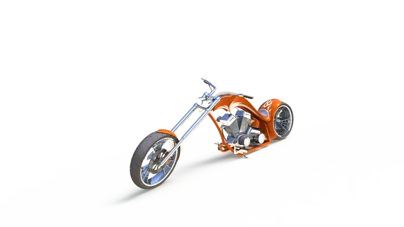
Several adjustments were made to ensure a clean and well-fitted model, as there were certain parts that were overlapping or coinciding with each other. Once these corrections were implemented, the chopper was ready for rendering, showcasing its final form and appearance.
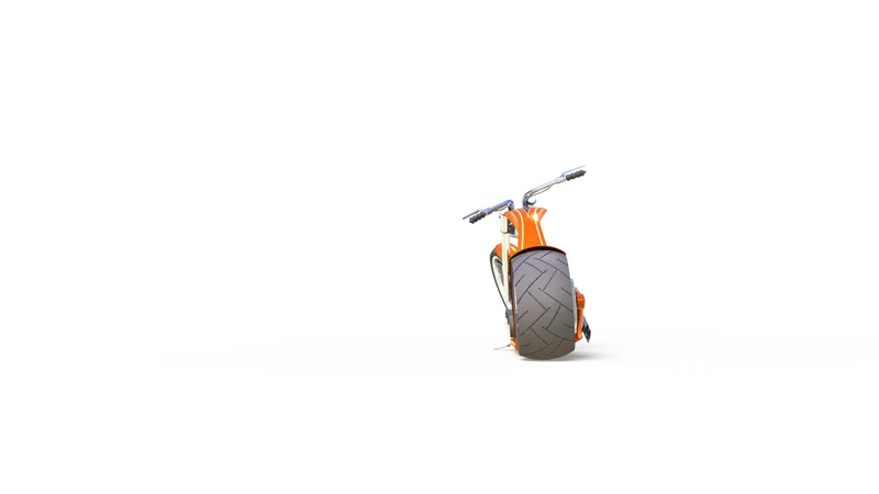
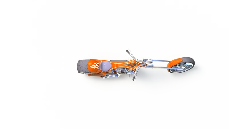
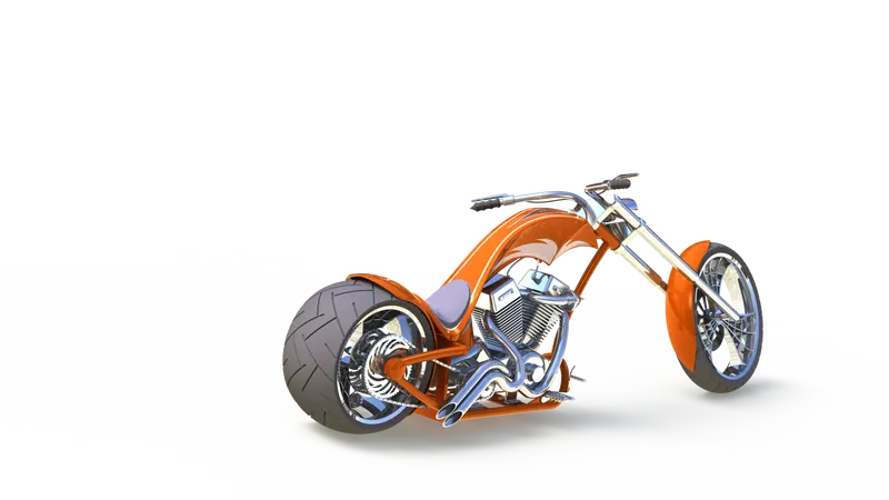
CAMERA VIEW :
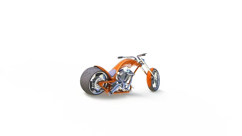
RENDERING THE MODEL
The act of rendering my chopper not only provided it with a lifelike appearance but also brought me immense satisfaction and joy. Solidworks Visualize enhances the visual appeal of your model, creating its most impressive aesthetic yet. The rendering process involved importing the model and meticulously applying unique appearances to each part. Subsequently, we placed the model in a suitable environment and adjusted the camera angles. Finally, we ensured high image quality and initiated the final rendering.