Photo Realistic Rendering
Modeling of The American Copper
Done by: Theeb Alqahtani
24/02/2023
Objective:
- To model the American Chopper using SolidWorks tool with the most efficient and time-saving techniques.
- To learn all the SolidWorks features and make your hands dirty by practicing them.
- To make the rendering of the parts and assemblies to get high-quality and resolution images of the design, so you can imagine the final product.
Introduction:
This project is provided by Skill-Lync and is about modeling the American Chopper bicycle. In this project, you will start by setting up your SolidWorks user interface till the assembling of all the parts.
Design Methodology:
During the design journey, you will get support from the recorded videos of the designs and the standby Skill-Lync support team. Therefore, the design will start from a high-level idea going deeper into the low-level parts and parts details. The following flowchart describes the methodology:
Description:
During the design a lot of features have been used, some of them were used frequently and some were used even once. The used features are listed below with these indicators (High, Mid, Low) to describe the frequency of each:
- Extrude boss (High).
- Extrude cut (High).
- Revolved boss (High).
- Revolved Cut (Low).
- Swept boss (Mid).
- Swept cut (Low).
- Lofted boss (Low).
- Lofted cut (Low).
- Fillet (High).
- Chamfer (Mid).
- Linear pattern (Mid).
- Circular Pattern (Mid).
- Mirror (High).
- Shell (Mid).
- Reference plane (High).
- Reference Curve (High).
- Reference axis (Mid).
Assembly Screenshots:
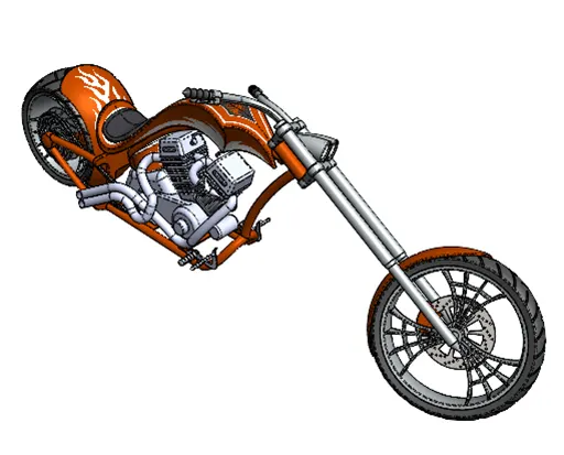
Figure 1: Isometric View.
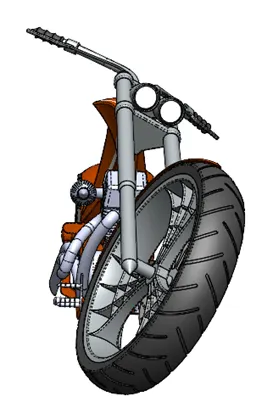
Figure 2: Front View.
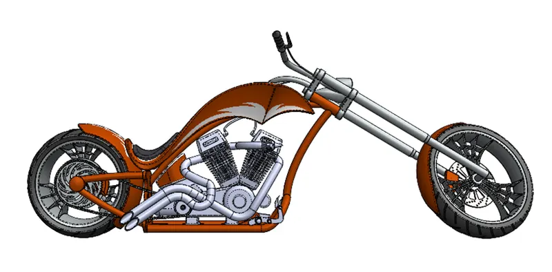
Figure 3: Side View.
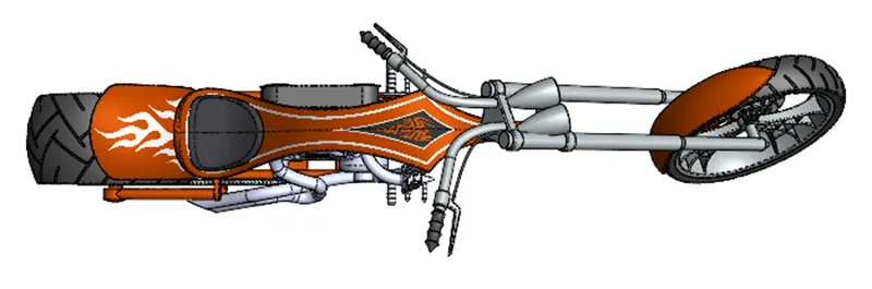
Figure 4: Top View.
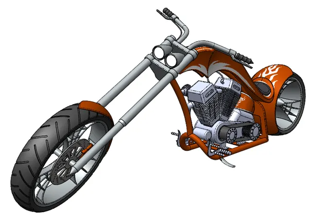
Figure 5: Camera Set-up View.
Rendering Screenshots:
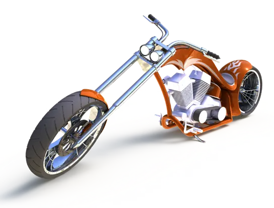
Figure 6: Camera Set-up View.
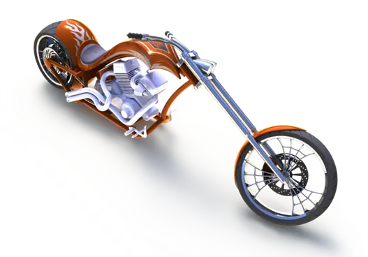
Figure 7: Isometric View.
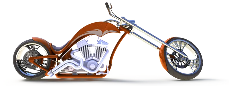
Figure 8: Side View.
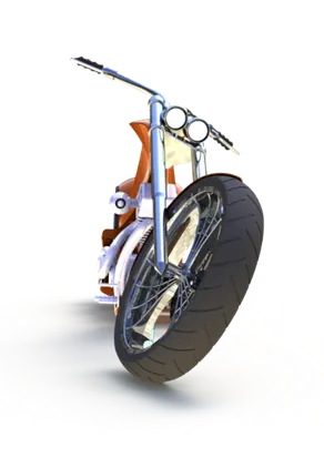
Figure 9: Front View.
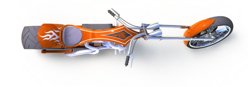
Figure 10: Top View.
Conclusion:
To conclude this report, I have learned many new features from this model and enhanced the knowledge that I knew.