Photo Realistic Rendering
DESIGN OF AMERICAN CHOPPER USING SOLIDWORKS
OBJECTIVES
Our objective is to learn solidworks tools by designing of American chopper. By designing different parts of chopper, we will get used to use interface of solidworks and different tools that is described in description. We will learn how to assemble parts and how to do different kind of rendering.
INTRODUCTION
Here is the overview of what we are going to do.
we will learn different tools while designing parts of chopper. Here are the different parts of chopper which we are going to design.
- Transmission belt
- Kickstand
- Front fender
- Rear fender
- Chain
- Oil tank
- Pedal
- Front wheel
- Rear wheel
- Front fork
- Chassis
- Engine
- Gas tank
after that we will do assembly of all this parts and then rendering of chopper with decals, environment.
Then we will do scene composition setup of light and then final render.
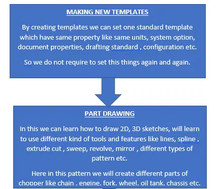
DESIGN METHODOLOGY
DESCRIPTION
Here we will discuss some major tools that we mainly learn in particular parts of chopper.
So, as we discussed in above design methodology first, we will make one templates for our easiness, after that we will start.
1. TRANSMISSION BELT:
In this part making various tools that is described one by one below.
- LINE:
We can use this feature to draw different types of line. Various option of line available here is horizontal, vertical, aligned.
also, some option like for construction, infinite length, midpoint line.
We can use according to our use.
- HIDE/SHOW ITEMS:
Here are many options of hide/show on menu bar that we can use while creating our sketch or solid body. Some items in this are view temporary axis, view camera lights, view dimension, view sketch relation etc.
- SMART DIMENSION:
By this tool we can give dimension to our sketch. In option setting we can also edit about how we want the dimension to look like e.g. We want dimension to see as 62.0 or 62.000 or just 62. We can give location dimension, size dimension and reference dimension.
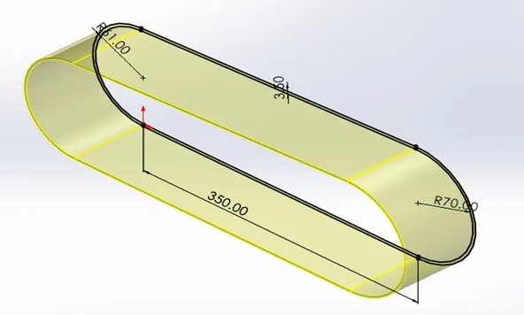
- OFFSET ENTITIES:
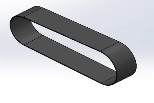
It is use to offsets one or more sketch entities by a specified distance. We used 3.5mm offset entities as shown in below image.
- BOSS EXTRUDE:
It uses to extrudes sketch or selected sketch contours in one or two direction to create a solid feature. Here we can give different kind of direction e.g. Blind, up to vertex, up to surface, midplane etc. we used this feature to extrude sketch drawn in transmission belt, we give 88mm extrude with blind direction as shown in above image.
- FILLET:
It is use to create rounded internal or external face along one or more edges on a solid or surface feature. Other variant in fillet available like constant size fillet, variable size fillet, face fillet, full round fillet. We use 1mm constant size fillet in transmission belt.
- APPEARANCE:
Appearance is something that what we want how our solid body will appear. Here is various option available like plastic, metal, painted, rubber, glass, lights, fabric etc. also subtypes in that available like in metal several another metal available steel, chrome brass etc.
in transmission belt we use matte rubber for appearance as shown in final image of transmission belt below.
2. KICKSTAND:
After belt we will see tools we used in kickstand. We used various tools but we will see only which we learn new tools that’s not used in previous parts.
- SPLINE:
To create spline in sketch. Spline is a curve which is defined by its continuously changing curvature to create an organic shape which is not possible by lines and arcs. we need to give two end points, direction, angle and way to spline according to our usage. We used this in kickstand to get nice smooth curve.
Generally, we can create two types of spline one is B-spline and another is style spline. We use B-spline in kickstand.
Spline handle allows to manipulate geometry about each point we placed.
Diamond shape allow to change the angular direction through a point.
The arrow allows to modify the tangent magnitude or weight of the handle.
The point on the end allows to modify both of the above function at the same time.
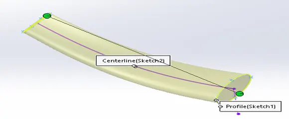
In kickstand we used spline to draw sketch that we can use further in loft feature.
- LOFT BOSS/BASE:
It is use to add material between two or more profiles to create a solid feature.
After drawing sketch by using spline and other we used this feature to add solid material as shown in below image.
- DOME:
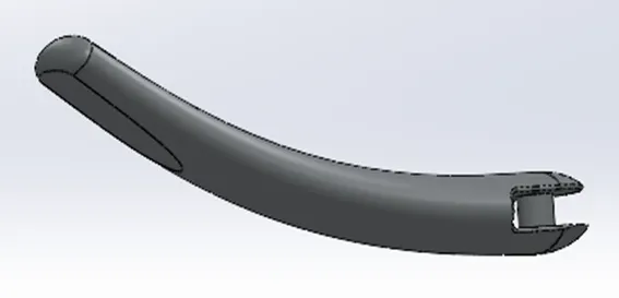
It is use to add one or more domes to selected planer or non-planer faces. Here elliptical dome option is available. We used elliptical dome on both ends of kickstand as shown in final image below.
- RECTANGLE:
Here we can draw different kind of rectangle like corner rectangle, center rectangle, 3-ponit corner rectangle, 3-point center rectangle, parallelogram.
In kickstand we sketched center rectangle that will use to do extrude cut.
- EXTRUDE CUT:
It is use to cut solid model by extruding a sketched profile in one or two direction if the cut affects multiple bodies in multibody parts, we can select which bodies to keep in the bodies.
In this part we used through all both option in direction to get desired part as shown in final image below.
- SPLIT:
It is use to create multiple bodies from a single body. We can create the bodies in the existing part or in separate parts.
Here we cut bottom face of kickstand by using split tool to get straight face on bottom as shown in below image.
3. FRONT FENDER:
In front fender we will learn mainly about arc, trim, revolve and dynamic mirror entities.
- ARC:
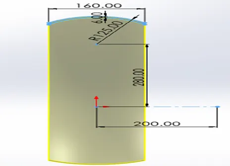
It is use to create an arc with using 3-point, one center and other two ends.
In solidworks three option are available center point arc, tangent arc, 3-point arc according to our usage.
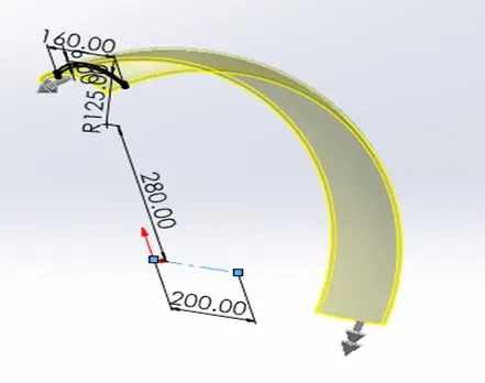
We used 3point arc to draw of R125 as shown below in image.
- TRIM/EXTEND ENTITIES:
It is use to trim or extend a sketch entity to be coincident to another or delete a sketch entity.
Also, power trim option available to trim adjacent entities by dragging across them. We used trim and extend entities to get two ends of arc.
- REVOLVE:
It is used to revolve a sketch or contours around an axis to create a solid feature. We used this in front fender. we need to create axis of revolution and need to give a direction.
As shown in below image of front fender we use revolve feature. we have drawn a sketch to give axis of rotation and then we gave direction1 5 deg and direction2 130deg to get our desired solid body by using revolve feature.
- DYNAMIC MIRROR ENTITIES:
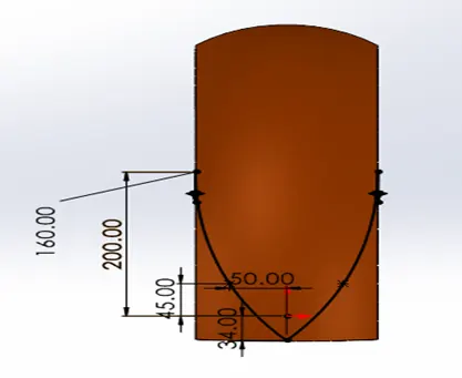
It is use to create sketch entities that are mirrored about a previously selected entity as you create them.
We used this feature to make sketch on front fender that used to split after that as shown in below image.
We made rear fender by following same method and tools.
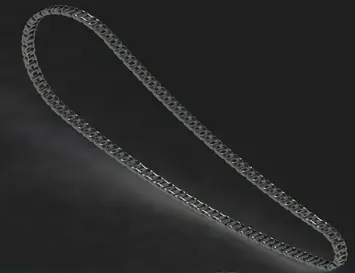
4. CHAIN:
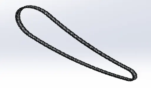
We made a curve of chain using spline and circle. Then we separately made two kinds of pin and make block. After that we made chain using pattern feature. So, we mainly learned curve driven pattern and mirror feature in this.
- PATTERN:
It is use to pattern feature, faces & bodies in one or two direction. We can select reference geometry to define the pattern. We can use different pattern like Linear pattern, circular pattern
- CURVE DRIVEN PATTERN:
It is use to pattern feature, faces and bodies based on a curve. We can align instances as tangent to the curve or to match the original alignment of the seed feature.
so here in chain we made two separate bodies and pattern it on curve that we made earlier as shown in below images. We have given offset value between two block and number of instances.
- MIRROR:
As its name it is use to mirror feature, face and bodies.
so, in chain we use this feature to mirror patterned block pin on another end of pin as shown in final image below.
5. OIL TANK:
In oil tank we mainly learn dynamic mirror entities, combine and shell feature.
- COMBINE:
This feature is use to do add, subtract and common operation between two or more solid bodies.
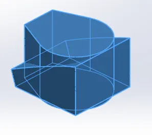
As in oil tank we have drawn two sketch and extruded both of them. So, to get desired body we used combine feature and selected common option in that.
- SHELL:
It is use to create thin walled hollow shell. we used this feature in oil tank. First, we made solid body of oil tank then we create shell of 10mm thickness in oil tank. If we see in section view of oil tank then we can clearly see the shell of 10mm thickness that we created.
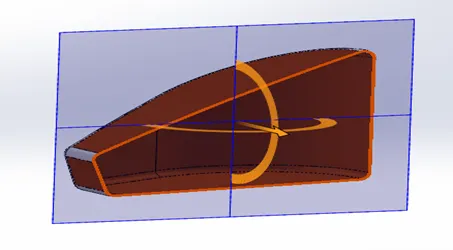
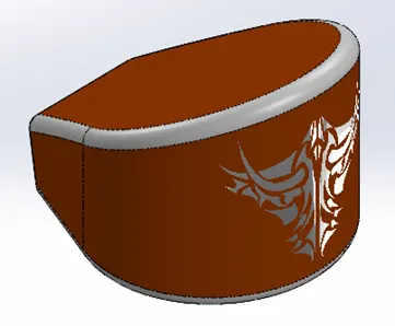
so, by using above feature we got our final part as shown in below image.
6. PEDAL:
In pedal we have used several tools like revolve, extrude boss, fillet, dome, chamfer, offset entities and linear pattern.
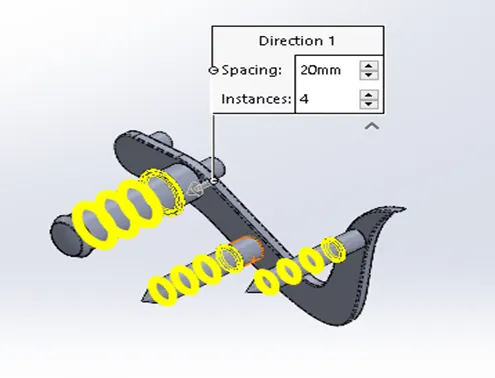
- LINEAR PATTERN:
It is use to pattern feature, faces & bodies in one or two linear direction. We can select reference geometry to define the pattern.
So as shown in above image we have used linear pattern to get groove in pedal. We gave 20mm spacing between them and 4 instances.
7. FRONT WHEEL:
Here we will understand design process behind spider webbed wheel rims.
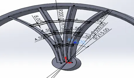
By using sketch feature we draw sketch and after that we use revolve feature to get outside edge of wheel. Now using spline, 3-point arc we made sketch for rim wheel as shown in below image.
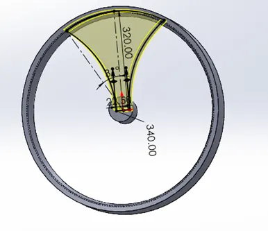
Then we did extrude boss and after that by using offset entities we get sketch and then extrude cut to remove material from there.
Now using 3-point arc and offset entities we draw sketch to get spider shape between them, then extruded that sketch by using up to vertex direction as shown in below image.
- REVOLVE CUT :
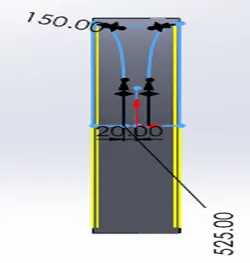
It is use to cut a solid model by revolving a sketched profile around an axis. If the cut affects multiple bodies in multibody parts, we can select which bodies to keep in the bodies to keep dialog box.
Here we used revolve cut to cut wheel rim in curve shape, so we draw sketch according to that and got a desired result by using revolve cut feature on that as shown in below image.
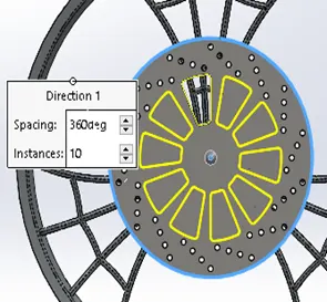
- CIRCULAR PATTERN :
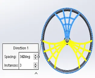
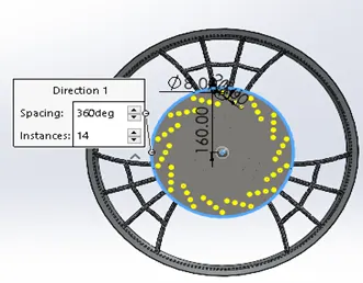
It is use to pattern features, faces, and bodies around an axis which we can define with various geometries.
Here we used this featured various time. For example we used to copy spider webbed design also in brake rotor as shown in below image.
- COMBINE :
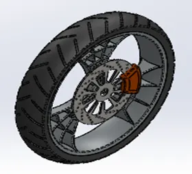
It is use to combine two or more solid bodies to create a single body or another multibody part.
In this we can do operation like add, subtract and common. we combine rim, rotor, caliper and tire in this part. So finally we got front wheel as shown in below image.
In rear wheel we adopt same kind of tools and feature so no need to repeat here.
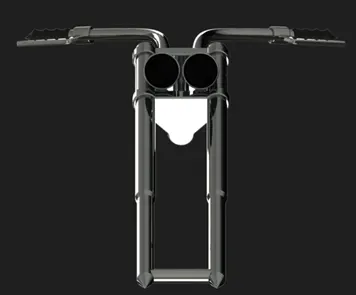
8. FRONT FORK:
In front fork we mainly learn about projected curve so we describe in detail below.
- PROJECTED CURVE:
Projected curve is a type of curve available in solidworks which is used to create a curve onto the face of the model or to create a 3d curve in solidworks.
It is used to projects a curve onto a face or sketch. The curve is a direct projection of the selected sketch onto another face or sketch. Projected curves are mostly used in the surface modelling to create a complex 3d curve.
There are two types of projections in projected curve.
- Sketch on face: sketch on face is used to create a projected curve on top of the face of the solid body or on top of the surface.
- Sketch on sketch: sketch on sketch is used to create a projected curve by using two different sketches created in the two different planes. The intersection portion between the sketches is converted as a projected curve.
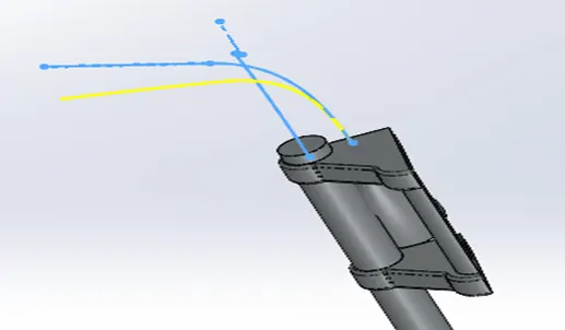
In front fork we used sketch on sketch projected curve two times first to get curve for handle and another to get curve for brake wire.
First, we draw one sketch in top plane and other in front plane then use projected curve to get projection of these two curves, that looks like 3d curve.
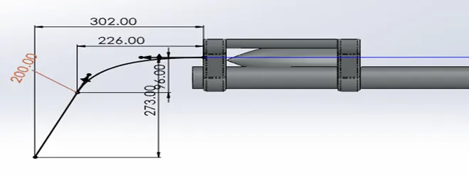
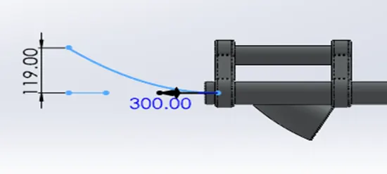
Yellow line in below image is projected curve.
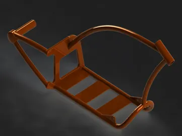
9. CHASSIS:
- SKETCH PICTURE:
It is used to add an image file into a sketch background.
Here we add sketch picture of American chopper into background so that it helps us to draw sketch of chassis.
In this we can locate sketch by giving x & y axis dimension, rotation and can give scale ratio of image. We can give transparency ratio according to our usage means how much light or dark image we required.
After using different tools, we got chassis.
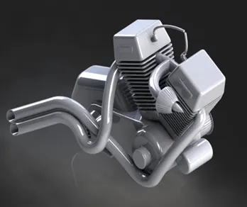
10. ENGINE:
- COMPOSITE CURVE:
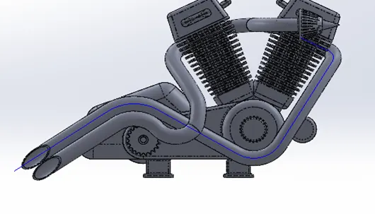
It is used to combine selected edges, curves and sketches into a single curve.
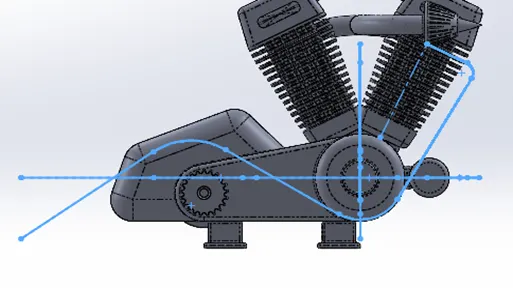
In above image there are two curves, so we combine that both curve using composite curve as shown in below image.
11. GAS TANK:
In gas tank we learned many tools which are related to surface.
- TRIM SURFACE:
It is used trim where a surface intersects with another surface, a plane or a sketch. We need to select trim type, trim tool and the surfaces to keep or remove. We can change how the trim boundaries extend from the end points of the trim tool.
So here we have drawn a curve shaped boundary on surface and trim that surface using surface trim toll to get curved shape surface.
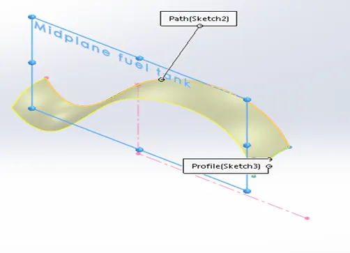
- SWEPT SURFACE:
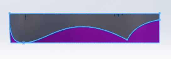
It is used to sweep a closed profile along an open or closed path to create a surface feature. We can use guide curves, profile orientations and twist angles to create different shapes.
As shown in below image we have drawn sketch for profile and path using spline and we gave direction vector to midplane of fuel tank in path alignment so that we can mirror it later easily.
- LOFTED SURFACE:
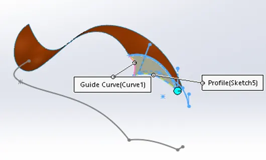
It is used to create a lofted surface between two or more profiles or sketch. Specify start and end constraints and add guide curves to control the path shape.
Here we used lofted surface to get front side surface of gas tank, for that we created guide curve using projecting curve and also given two constraints as shown in below image.
- BOUNDARY SURFACE:
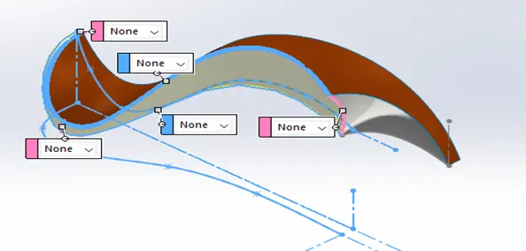
It is used to create a surface between profiles that can be tangent or curvature continuous in all direction. In the graphics area use connectors or instant 3D drag handles to shape the boundary surface.
So here to make side surface of gas tank we used boundary surface tool. We have selected projected curve as a boundaries and we selected them by using selection manager because edge of the surface is in multiple segments. We can see curvature display and can set according to our requirement like mesh preview, zebra stripes and curvature combs.
- KNIT SURFACE:
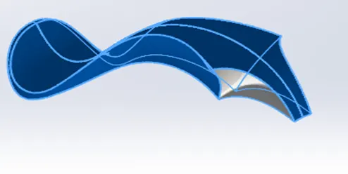
It is used combine two or more adjacent, nonintersecting surfaces into a single surface body. The surfaces must joint at an edge, if the resulting knit surface encloses a volume. We can create a solid body from the property manager.
We did mirror after making half of the part and then select all the surface and combine all of them using knit surface.
- SPLIT LINE:
It is used to projects a sketch to curved or planer faces, creating multiple separated faces.
After making seat sketch, we have projected sketch to top surface of gas tank as shown in below image.
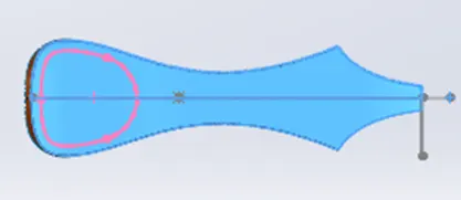
- EXTRUDE SURFACE:
It is used to extrudes a sketch or sketch contour in one or two direction to create a surface feature. We can control where the extrude starts from and define its direction and extent.
We have extruded a sketch on gas tank of 25mm to get seat as shown in below image.
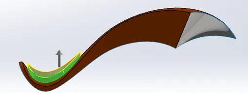
- SWEEP CUT:
It is used to cut a solid model by sweeping a closed profile along an open or closed path. A common usage it to create a cut around a cylindrical body. If the cut affects multiple bodies parts, we can select which bodies to keep in the bodies to keep dialog box.
As shown in below image we used this feature to get curve shape cut in bottom of gas tank.
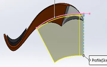
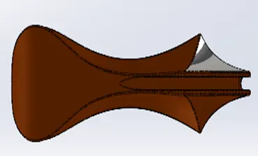
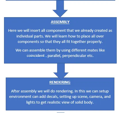
ASSEMBLY
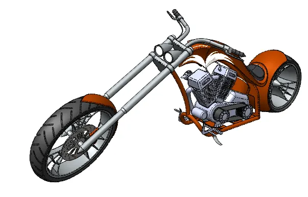
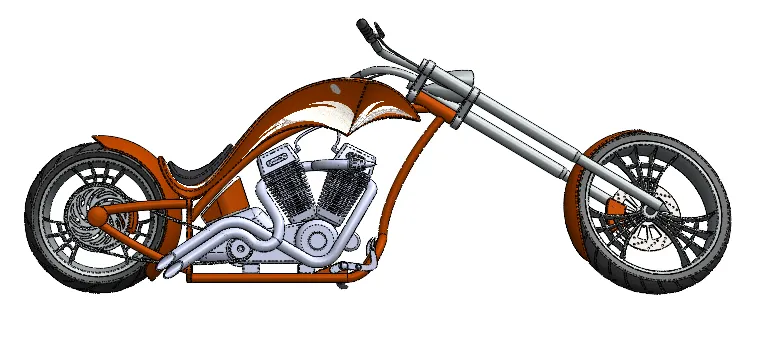
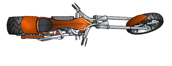
In assembly we open new document and select assembly template. Then we insert component of chopper that already we made one by one by using different mates. We will see some of the mates that we used during assembly.
First, we insert chassis and make its midplane as assembly’s midplane.
COINCIDENT MATES:
This mate is use to coincident one component face to another component face.
We used this mate when we insert engine and make coincidence it with chassis.
DISTANCE MATES:
This mate is use to give distance from edge, surface or face of one component with respect to another component.
We used this mate to give 20mm distance between engine and chassis.
CONCENTRIC MATES:
This mate is use to give concentric relation in assembly between shaft and hole basis parts.
We used this mate in kickstand and pedal with respect chassis in assembly.
LIMIT ANGLE MATES:
This mate is use to give limit in angle so that body can rotate in limited angle.
We used this in kickstand to give angle limit of 0 to 75 degree as we know in there required some angle to rotate that part.
WIDTH MATES:
We can use this mate to assemble two or more components at some width or centered one component with another.
We assembled transmission belt in pulley by using centered width mates.
ANGLE MATES:
This mate is use to give angle to one component with respect another component.
We used this mate to give angle to transmission belt w.r.t. engine.
POSITION MATES:
This mate is use to give position to parts which can also move but after fixing its position, we can get its actual position as we required.
We use this mate to front fork to give position.
TANGENT MATES:
This mate is use to give tangent relation between two or more component.
We used this relation between wheel and bottom plane of assembly so that it will look like it is attached to the bottom.
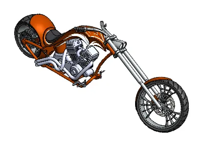
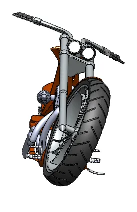
After using several mates we got final assembled parts, here are some image is shown below.
RENDERING
In rendering we learn how to setup scene, environment and how to render decal on existing parts.
Rendering is the process of generating a photorealistic or non-photorealistic image from a 2D or 3D model utilizing a computer program.
In scene rendering we can change basic scene, studio scene, presentation scene and background.
We can add multiple properties, material, appearance or configuration of any particular part or whole body in display state and can save it.
In render tools we can apply decal to faces in a model. We can use the decal property manager to select decal, the faces where we want to add and the illumination of the decal.
We can also add direction in camera according to our usage and also in lights where we want more brightness, we can add light direction at specific region. After setting we can save it and can use that camera view in view section.
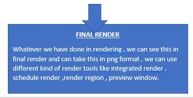
We can preview our render by preview window, final render, schedule render.
- Schedule render: it is used to schedule a render in background. We can render a task and generate reports through solidworks task schedule app.
- Preview window: it is used to open the photo view 360 preview window that display the rendered models.
- Final render: it is used to make detailed adjustment to the final render or compare two rendered and view statics.
- Render region: It defines a graphics window region for preview or final rendering. It evaluates lighting and appearances and adjusts render setting without changing the view orientation.
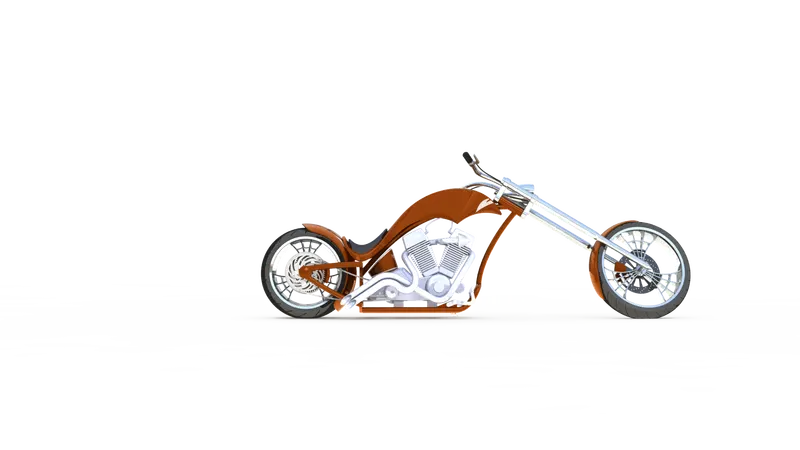
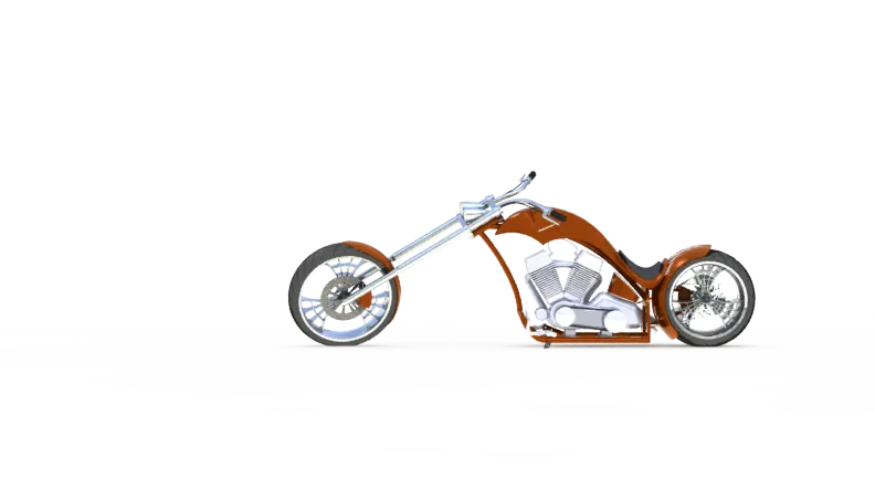
so here are all images of rendered parts of American chopper.
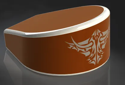
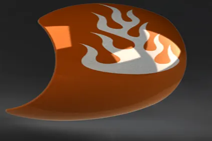
Oil tank rear fender
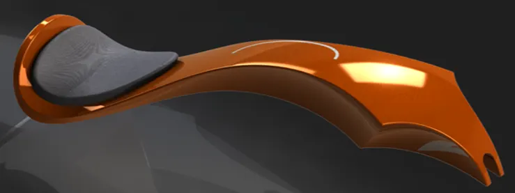
Gas tank
Chain Chassis
Engine Front fork
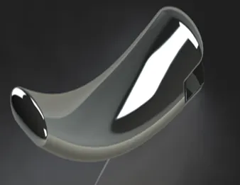
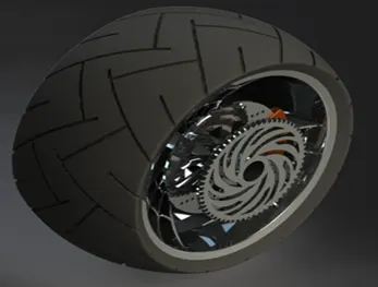
Kickstand Rear wheel
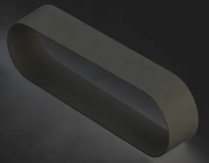
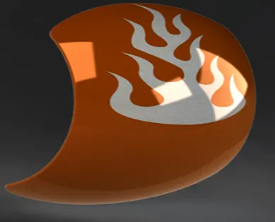
Transmission belt Rear fender
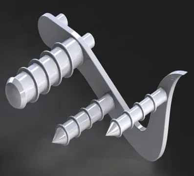
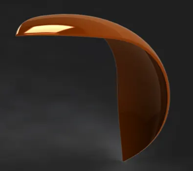
Pedal Front fender
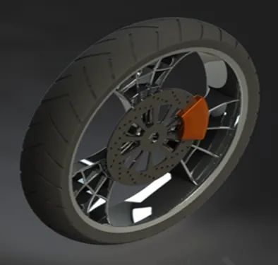
Front wheel
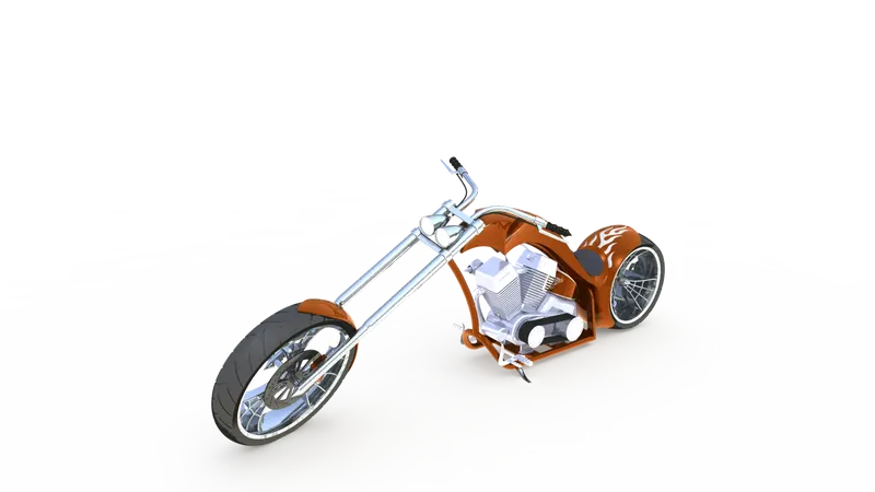
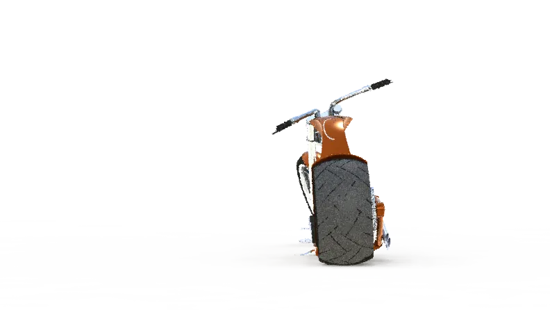
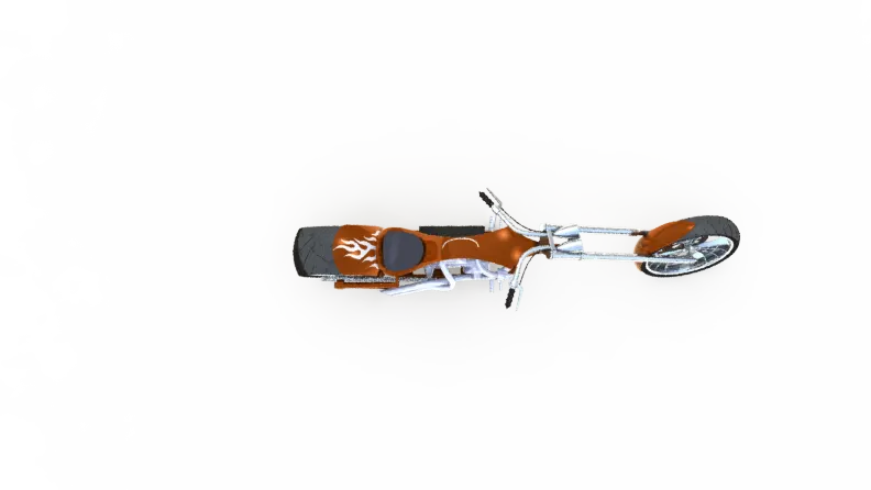
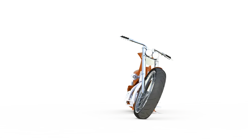
Here are all final image of final render.
CONCLUSION
By making American chopper we learn various tools of solidwork and used to use soildwork interface. We learned how to assemble different parts and how to do rendering of solid body to get realistic view.
NOTE :
decal is not look as shown in video due to software error also discusseded in one to one session, so take note regarding this.